 Oskar Weigl
In order to finish manufacturing of the first batch of v3 boards, we need a simple way to test if the boards work as they come off the automated assembly. Since I want to get the boards out to people as soon as possible, I will only test the very basic functionality. More features can be added to the tests later.
The basic functionality I want to test is:
- Does the logic supply power up?
- Does the firmware boot up?
- Execute some simple test voltage vectors to test the current sensors.
- Spin a motor open loop (no encoder feedback)
- Does the encoder work?
- Spin the motor closed loop.
- Same tests on the 2nd motor channel.
This requires two main components: the test hardware and the test software. In this post I will only focus on the test hardware.
Test board
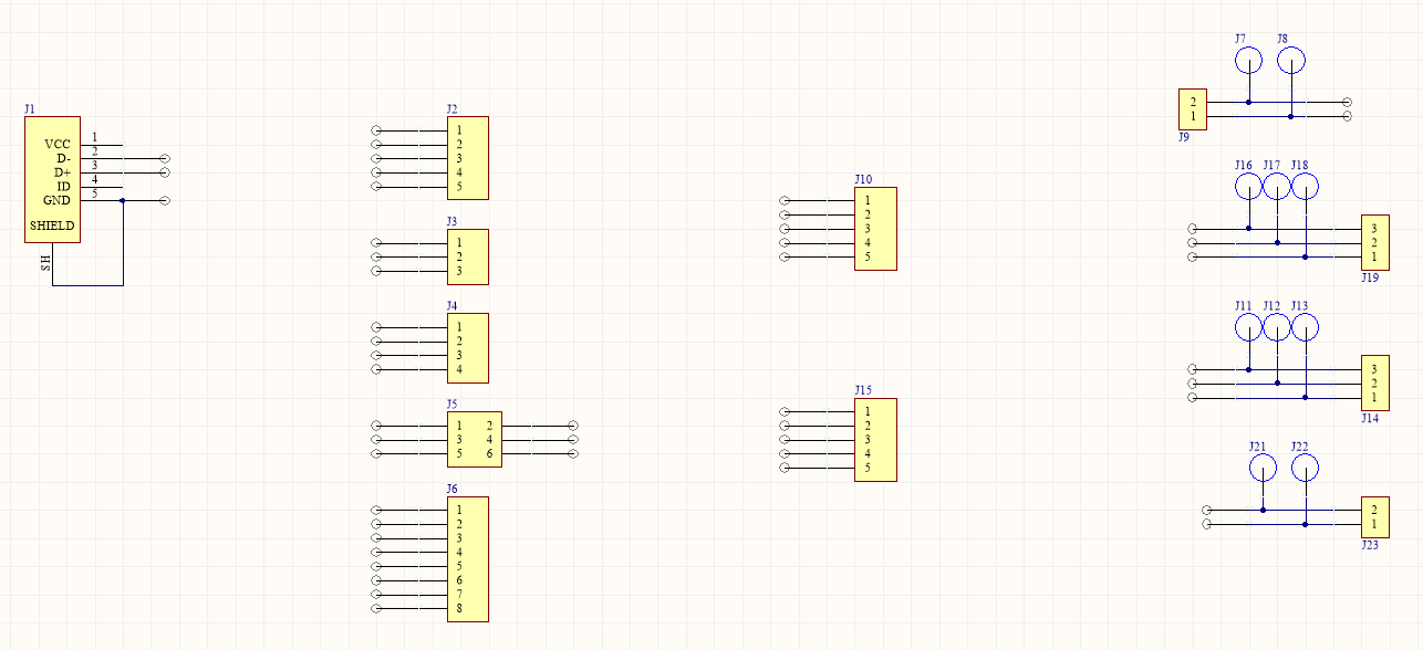
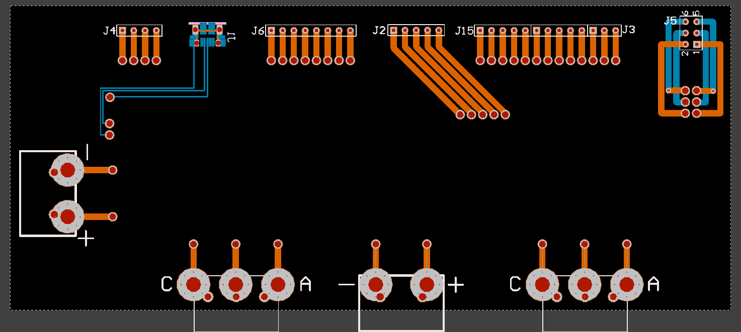
To quickly test the board, one of the best ways is to make a bed-of-nails that can make connection to all the required places on the board for testing all in one go. The idea is to use spring-loaded pins like these pogo pins that sit on a separate PCB underneath that can break out the connections to the test equipment. @Thomas Branch made one on Circuit Maker here. At the time of writing the design is not completely finished reviewing yet, but should be done soon.
Here are some picutres:

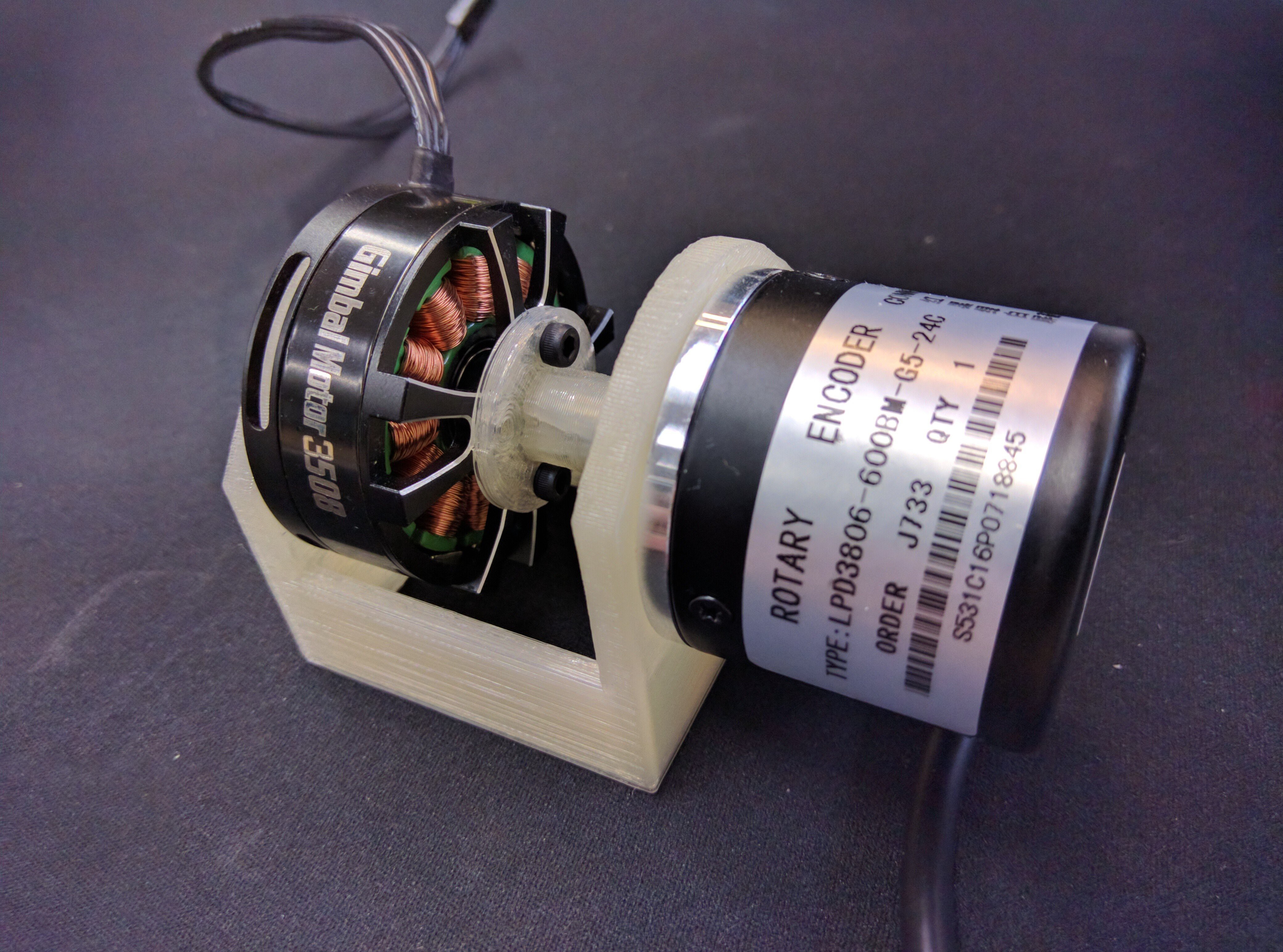
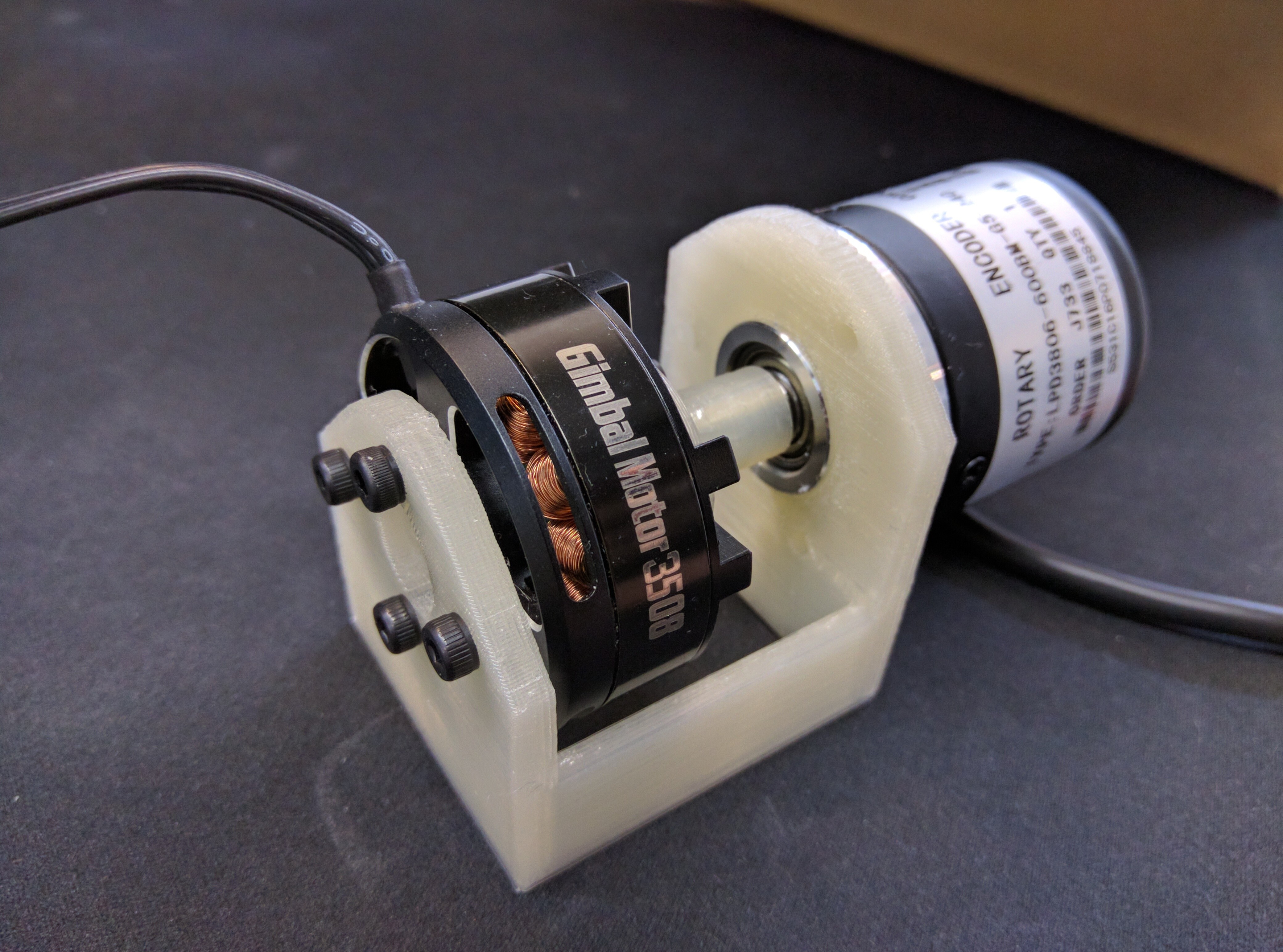
Encoder - motor rig
To do the aforementioned motor tests, we need a motor and an encoder for each channel. The setup is designed to be as simple as possible, so it is just a motor directly coupled to an encoder, nothing else. I picked this gimbal motor since I just happened to have it lying around. But I picked a gimbal motor in particular since its high phase resistance means that if there are any bugs that cause the voltage to be switched on much higher than intended, it means that it doesn't just blow up immediatly, just melts slowly (;
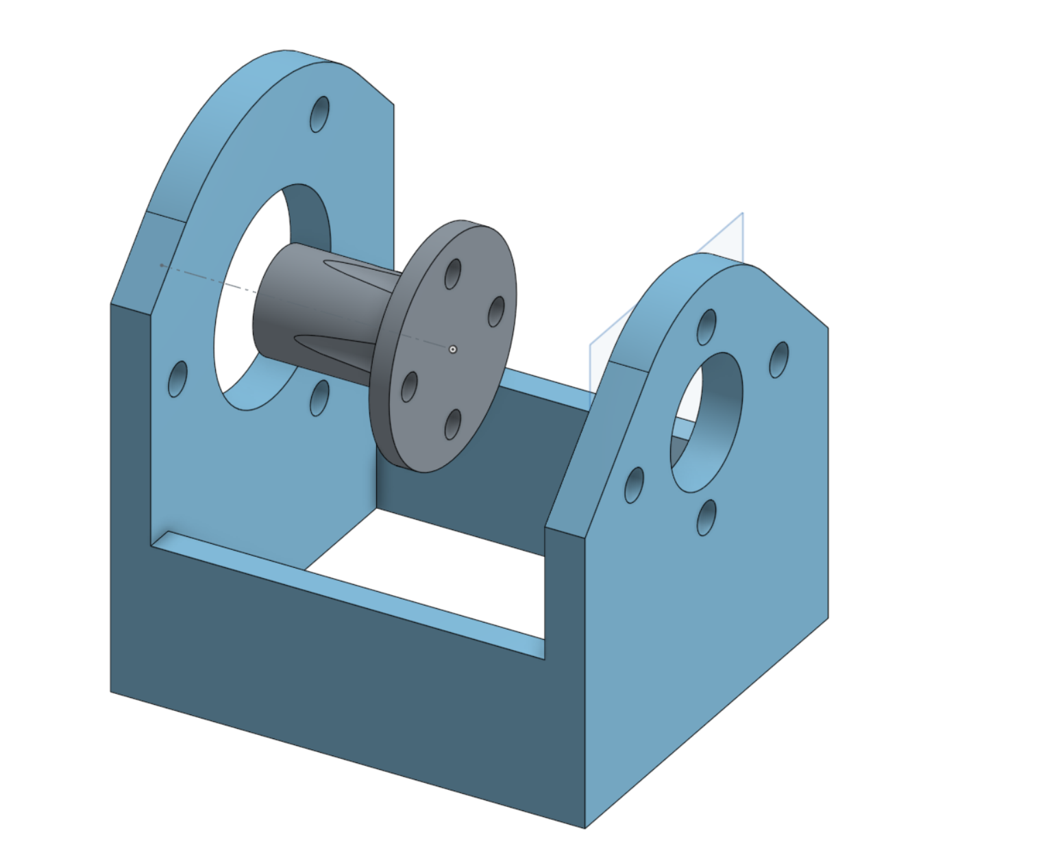
I picked this encoder. You can find the design on onshape. Below are some pictures:
Discussions
Become a Hackaday.io Member
Create an account to leave a comment. Already have an account? Log In.