 AndresRengifo
Capabilities and Demos
Overview
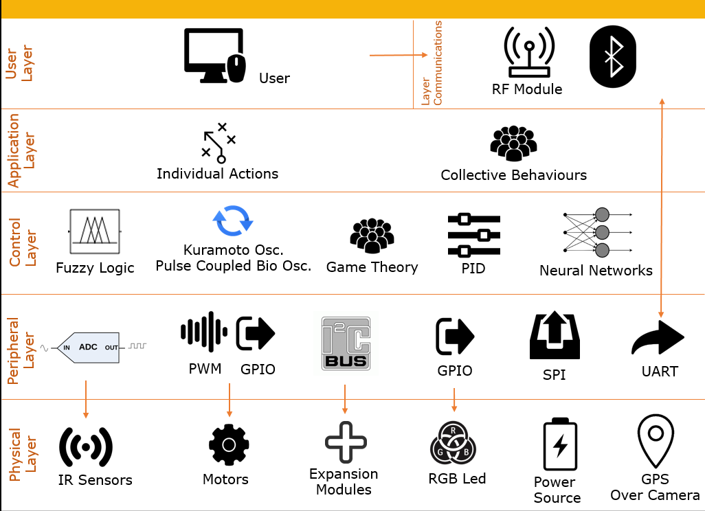
"The general design is presented using layers. The bottom layer supports the physical components that compose the robot, such as motors, IR sensors, expansion sockets and modules, RGB LED, LiPo battery, LiPo charger, and a global positioning system that uses an overhead camera. The peripheral layer is powered by the ATmega168A microcontroller, which manages and drives all the physical components. Above that, the control layer performs the necessary actions to safely drive the robot in its environment and complete tasks. The application layer describes the individual and collective actions that emerge when the robot or group of robots are operating. Finally, the top layer allows the user, through the communication layer, to debug, run, start/stop, and program the robots.
Hardware Description
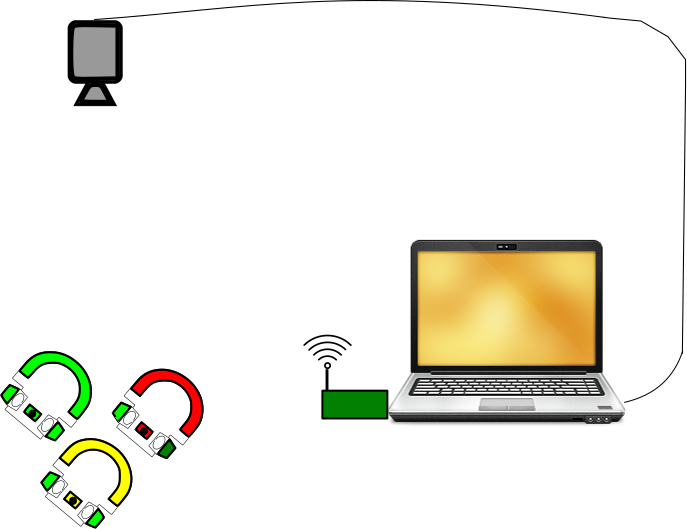
The complete hardware is shown in the previous picture and is composed of robots, a computer, a web-cam, and a controller board (the green one attached to the computer). The user can write codes to program the robots using AVR-Studio on the computer. Additionally, the computer runs the 'Central controller' software, which enables the sending of commands to the robots and the processing of web-cam information for global positioning. The 'Central controller' software is compatible with any web-cam with a minimum resolution of 340x480 and 30 fps. The computer application communicates with a Central Controller board via USB to send user commands to the robots wirelessly. The 'Central controller board' has an AT90USB162 microcontroller that receives USB data from the computer and sends it to the robots using the NRF24L01 module. It also allows for wire programming via AVR-ISP
Robot Main Board
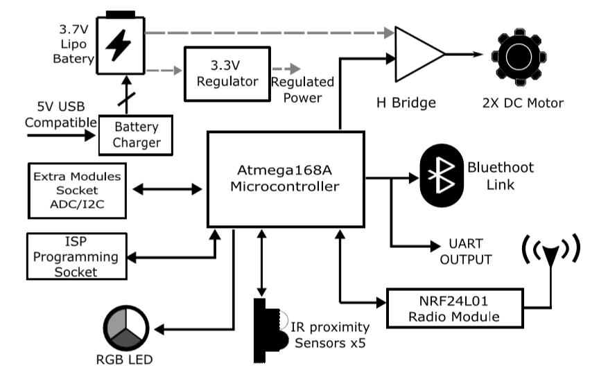
- Locomotion subsystem: It is based only on the contact between the rotor of two tiny 3V electric motor and the surface. The manage of the motors speed and direction is done by the microcontroller, using PWM and digital pins, using the TB6552 driver .
- Communication: Here, we use an ultra low cost transceiver RF (at 2.4GHz) module NRF24L01, which gives the robot the possibility to interchange data with the operator and other robots.
- Power and Charging Management: The electronics are powered by a 3.7V, 200mAh LiPo battery. A voltage regulator is used to maintain a constant voltage of 3.3V and enable operation above 5 hours of constant working. Also an external LiPo charger has been built that uses an MCP73833 to manage battery reload.
- Assembly and Costs: Three custom 3D print parts for easy setting-up and calibration of the motors and IR sensors are designed. These two pieces do not need to use glue or screws. An exploded view of mechanical assembly is shown. The 3D pieces models are available Here.
- The Electronic design is available Here.
Lipo Charger
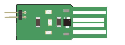
The Lipo charger board is USB (5V) compatible, it allows to charge a single cell Lipo battery, using the IC MCP73833. It recommendable to use a GP connector between battery and board (take care about polarity !!). The design and fabrication files are available Here
Central Controller Board
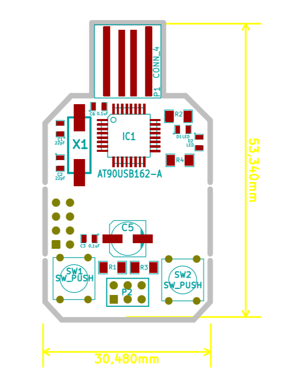
The Central controller board is also USB (5V) compatible. It has two functions:
- First one: It can be used as a programmer emulating the AVRISPmkII programmer. Refer to the software section to it usage. When you have configured the Central controlled board as a AVIPSmkII programmer you just have to interconnect the ISP pins of this board and the ISP robot socket and avr studio to code and run your code.
- Second one: It can be used as Wireless commander to the robots, for this you just have to plug-in the board and install the required drivers (Software Section).
This board has one ISP connector, a USB port, and two buttons: left one is the reset button and rigth one is the ~HW button that allows enter lo the Fip-mode.
- The Flip mode allows, charge new firmwares to the board, using the Flip software. To enter in this mode you have to plug the board to pc via USB, and then holding de ~HW button press the rest button, then release the ~HW button and open Flip Software.
All the hardware design is available Here.Software Description
The software developed is divided in three parts. The first one is the robot firmware, that allows drive the motors, read the sensor, and implement controllers. Second one is the "central controller board" firmware and drivers. Finally the user interface to send start/stop commands to the robots and processing overhead camera images.
Robot Skecth
The Robot Sketch is a basic template write in C code that shown the basic functionalities of the robot. It also provides all ( Here ) the libraries to drive the complete set of the robot peripherals, read the entire sensors set, and also apply controllers to perform different tasks. Read the documentation inside the code. For work over this sketch you are going to need the avr studio IDE.
Central Controller
The code for central controller firmware is available Here The code for central controller computer software is available Here.
AVRISP programmer
As it was explained in the previous sections the central controller board can be used as a programmer using AVRISP-mkII. In the Programmer folder you could find AVRISP.hex and the Flip Installer - 3.4.7.112.exe. Enter in the Flip-mode and the load the AVRISP.hex file. Then you could use the programmer as AVR-ISPmkII programmer.
Central Controller Firmware
In the folder "programmer", the ATMEL-STUDIO project "USB NRF24L01" is the firmware to communicate the Java user interface over USB protocol, with the robots, wirelessly via NRF24L01 module.
User Control
In the folder CentralControllerSW you could find the open CV installer and the JAVA-USB utility. Also the Java project "Central Controller" to communicate the user with the robots and camera via Java program interface. You could use Eclipse-IDE to modify and launch this code.