 caver.adam
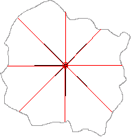
In a perfect world we could get a laser module where the laser shoots straight out of the module and straight back to the detector and is centered at the origin of our gimbal space...but this isn't a perfect world. The detector has to be physically (and optically) seperated from the laser. In the modules I'm considering the spacing is often ~25mm (1in). The first figure below shows how it would work if the laser came straight out of the module/gimbal and was centered at the origin. No transformations of the distance needed. Only a distance and two angles to collect.
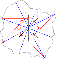
One of the modes that can be different is that the module has a stereoscopic spacing between the laser and the detector and the output can be off-center. If the module is in front or behind the origin we can simply add or subtract distance to adjust. However, if the module is off to the side of the origin we end up scanning an entirely different scene. Fortunately (as shown below) the scene is still scanned evenly, and only the ending location from the center is off.

In the blue lines below the actual vector from origin is indicated. Because we know the red vector (we measured it) and we know the offset of the laser emmitter from origin (we manufactured it) we can do a vector addition to determine the actual location of the reading from origin. This only takes one calculation (which can greatly increase computational requirements).
The other problem we can run into is that the laser does not shoot straight out of the module. This is indicated by the manufacturer of the SF30-B (although they do not specify an angle of deviation from center). However, as shown below, this isn't really a problem if the laser is originating at the origin, we simply add this angle of deviation to the angle that is set by our motors. We can do this easily because we are calculating the vector from the motor angle, so we can do the angle adjustment before the vectors are calculated.
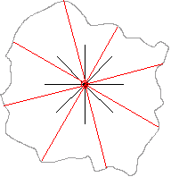
The problem starts when we once again have an offset from the origin.

Now we have to account for the offset of the laser from center, and for the angle of deviation which is two calculations (and offset is still using a lot of processing power).

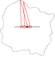
Also, the manufacturer of the SF-30 recommended that the module be centered. They also mention the sensor becomes less accurate over a close range due to parallax error. However, parallax error is based on distance. The centering of the laser only affects distance in that the laser will strike a different place on the target surface (as shown below).
This leads to some options for using a sensor with a large stereoscopic distance between the laser and the sensor.
1) Switch to an easier to use sensor at a significant cost (because it has to be built from scratch).
2) Center the sensor on the center of the gimbal. This will require software processing to correct the final output based on angle variation and horizontal offset calibration values.
3) Center the laser output on the center of the gimbal.
a) Center the back of the laser at the center of the gimbal with the back of the module aligned with the gimbal axis. This may cause a small offset error because the laser is exiting at an angle. (physical calibration)
b) Perform (a) but offset slightly more to account for the laser angle (physical calibration)
c) Center the exit point of the laser (inside the module) on the center of the gimbal. The module may be calibrated to base distance on the back of the module and the distance results will need to be adjusted accordingly. (physical and software calibration)
Result: Calibration procedures will definitely be needed.
Secondary Result: Build a gimbal wide enough to move the sensor during testing and figure it out later with a design of experiments.
Discussions
Become a Hackaday.io Member
Create an account to leave a comment. Already have an account? Log In.