 Mike Rigsby
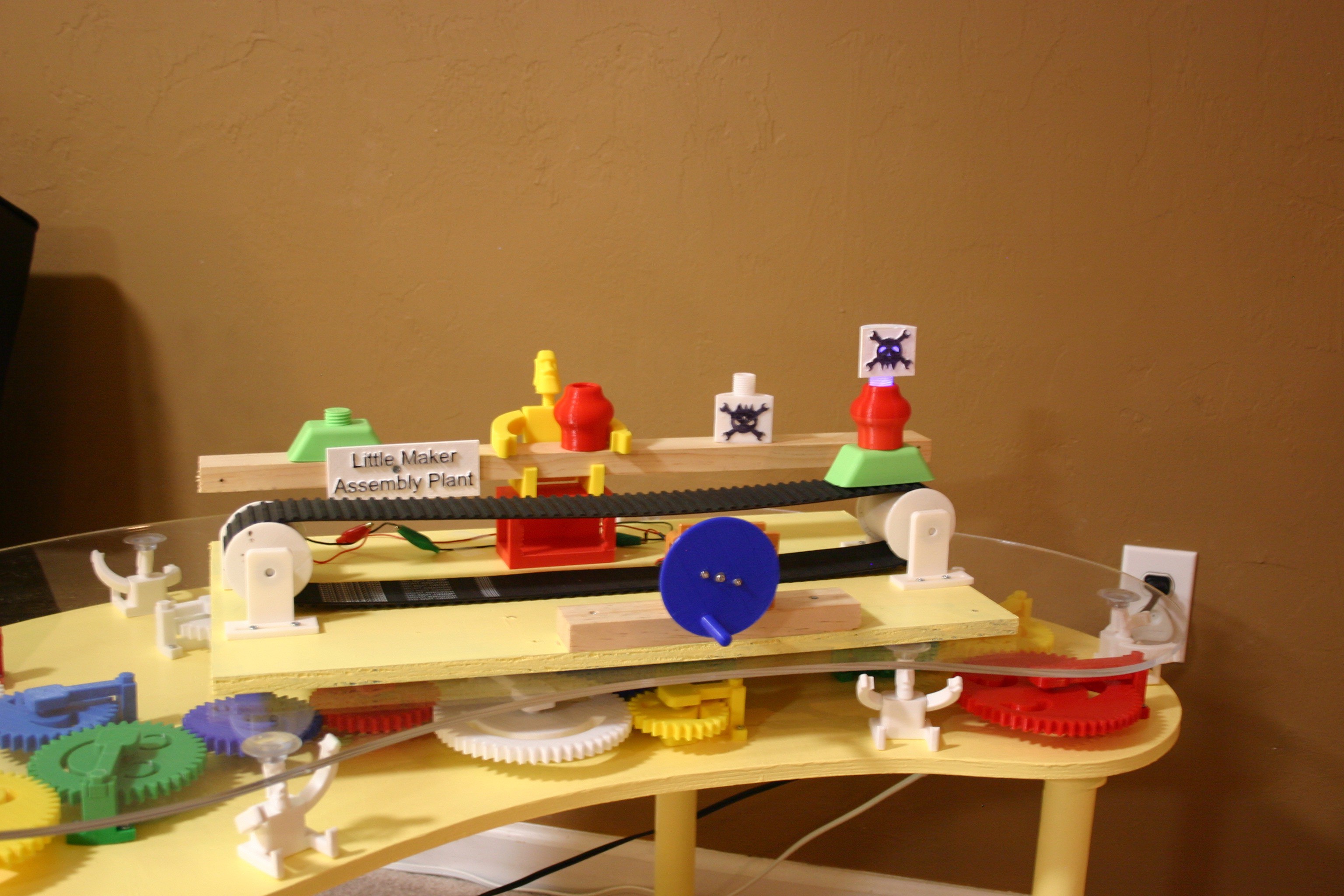
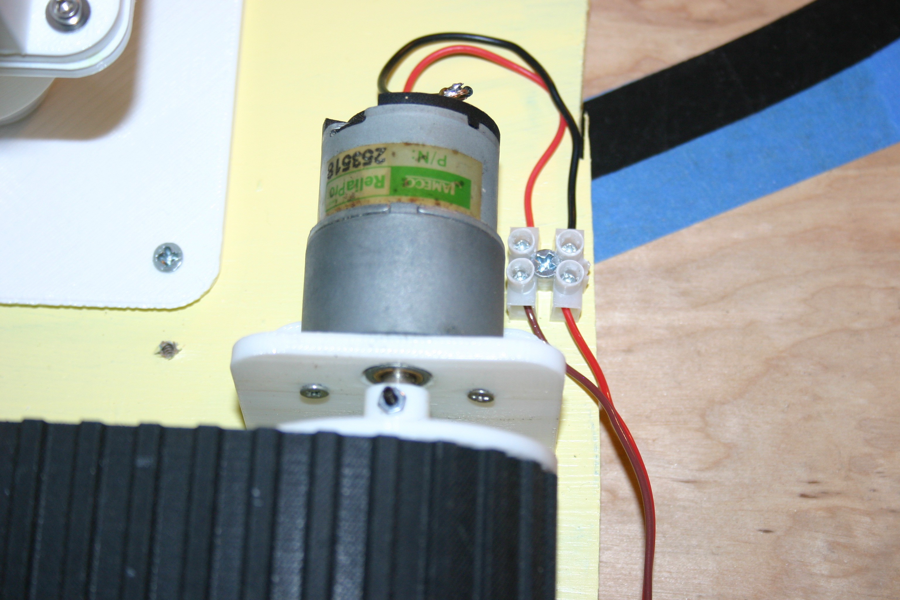
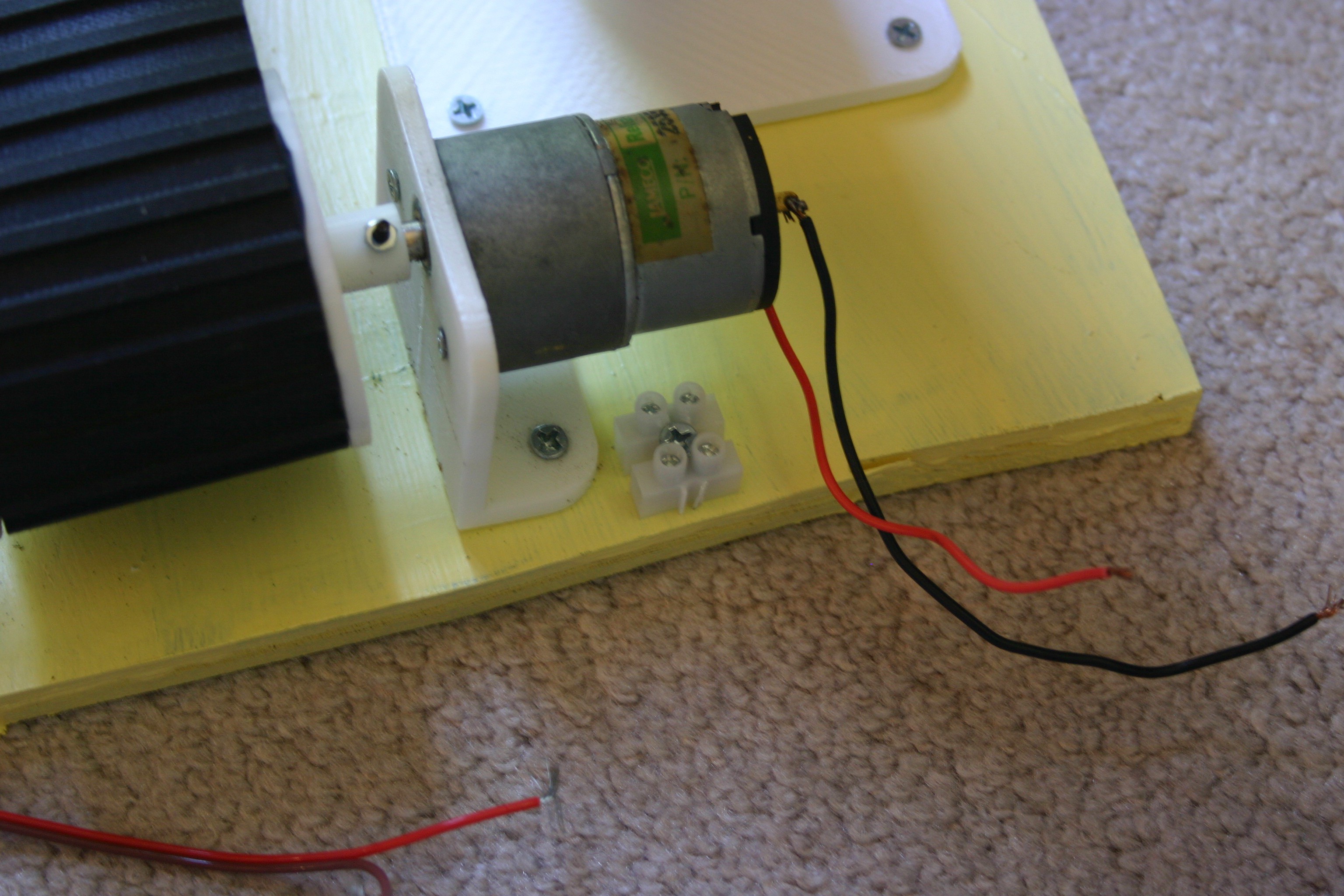
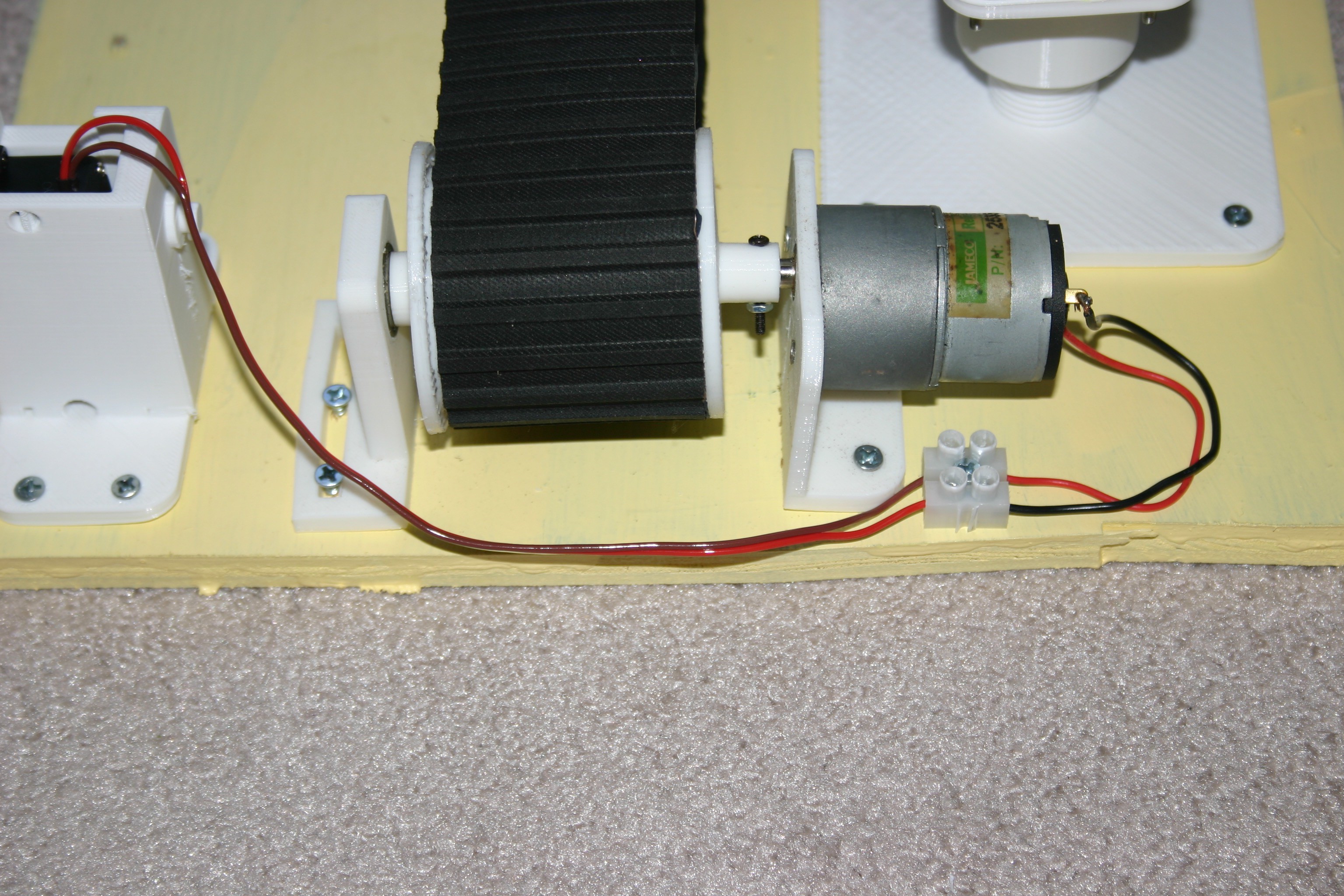
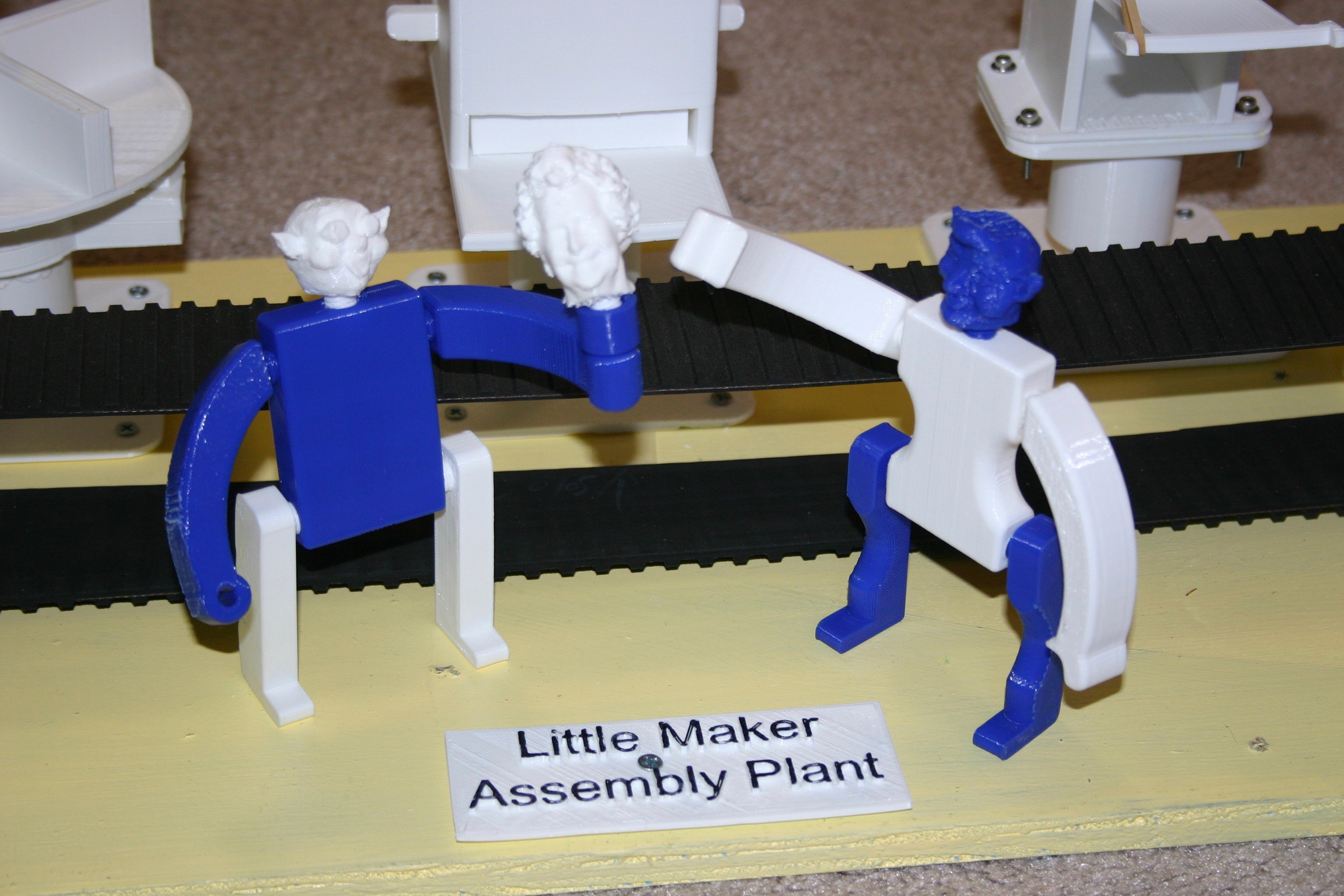
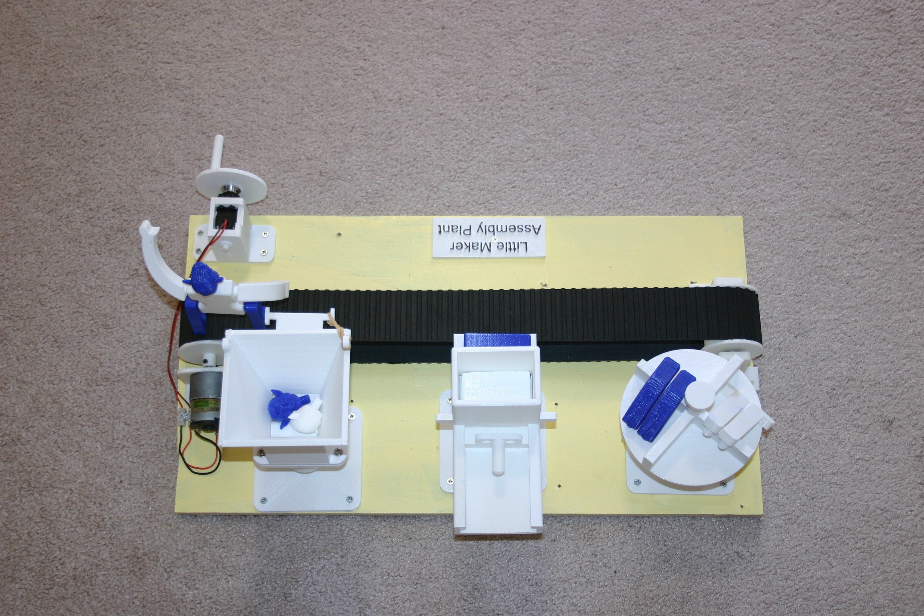
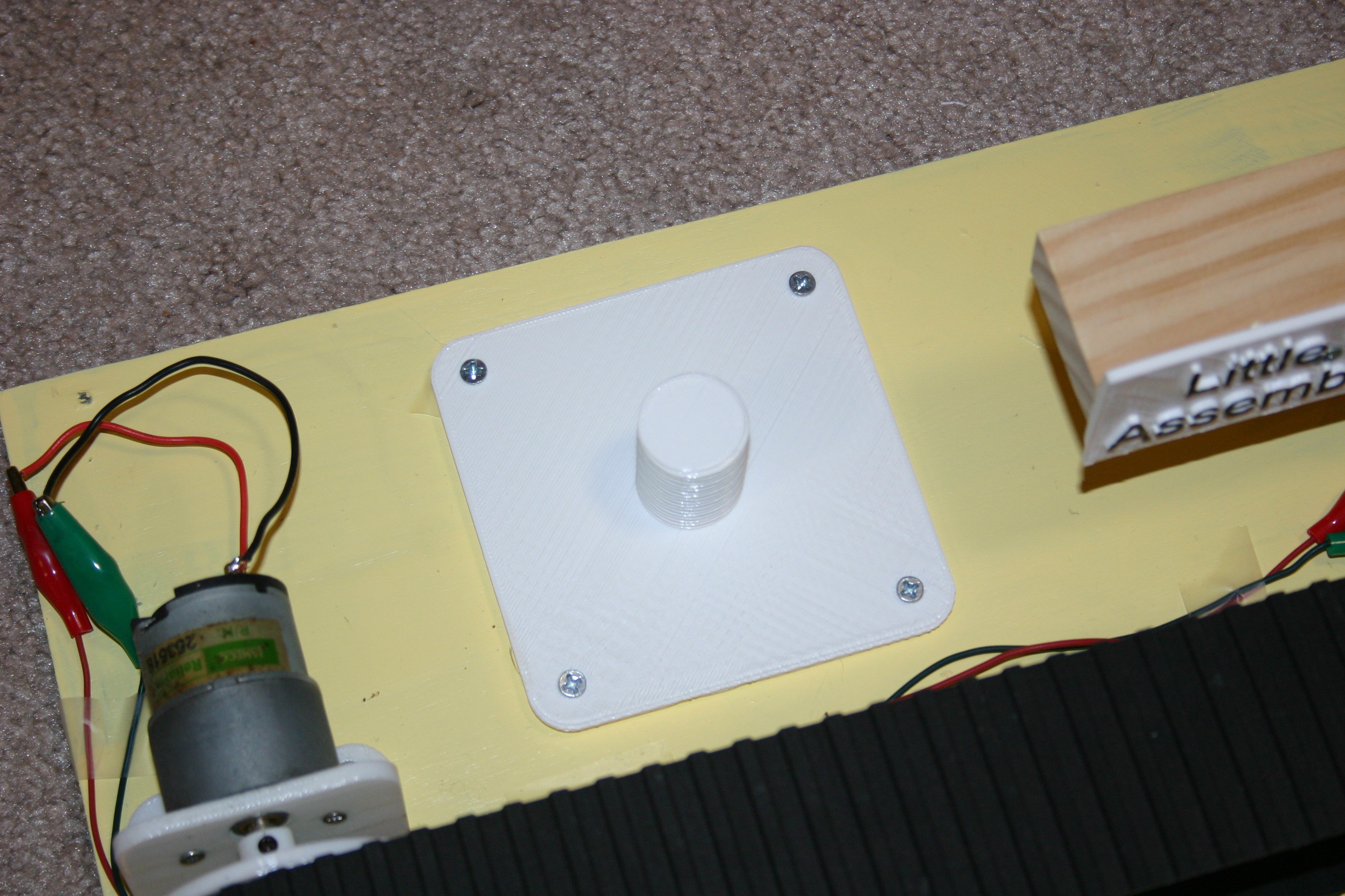
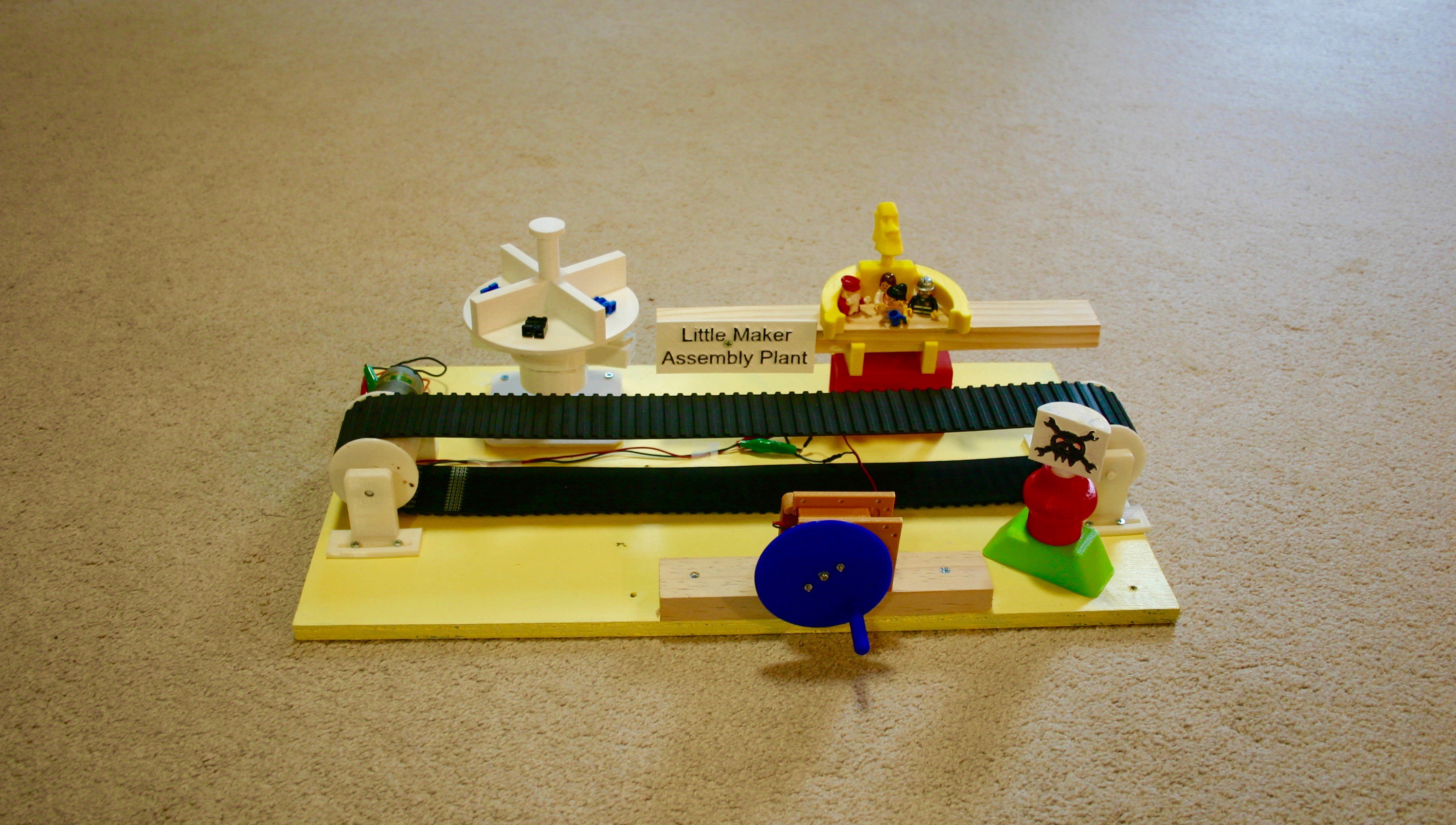
The project is starting to come together--here's a functioning line.
Going forward I hope to create:
More Modules
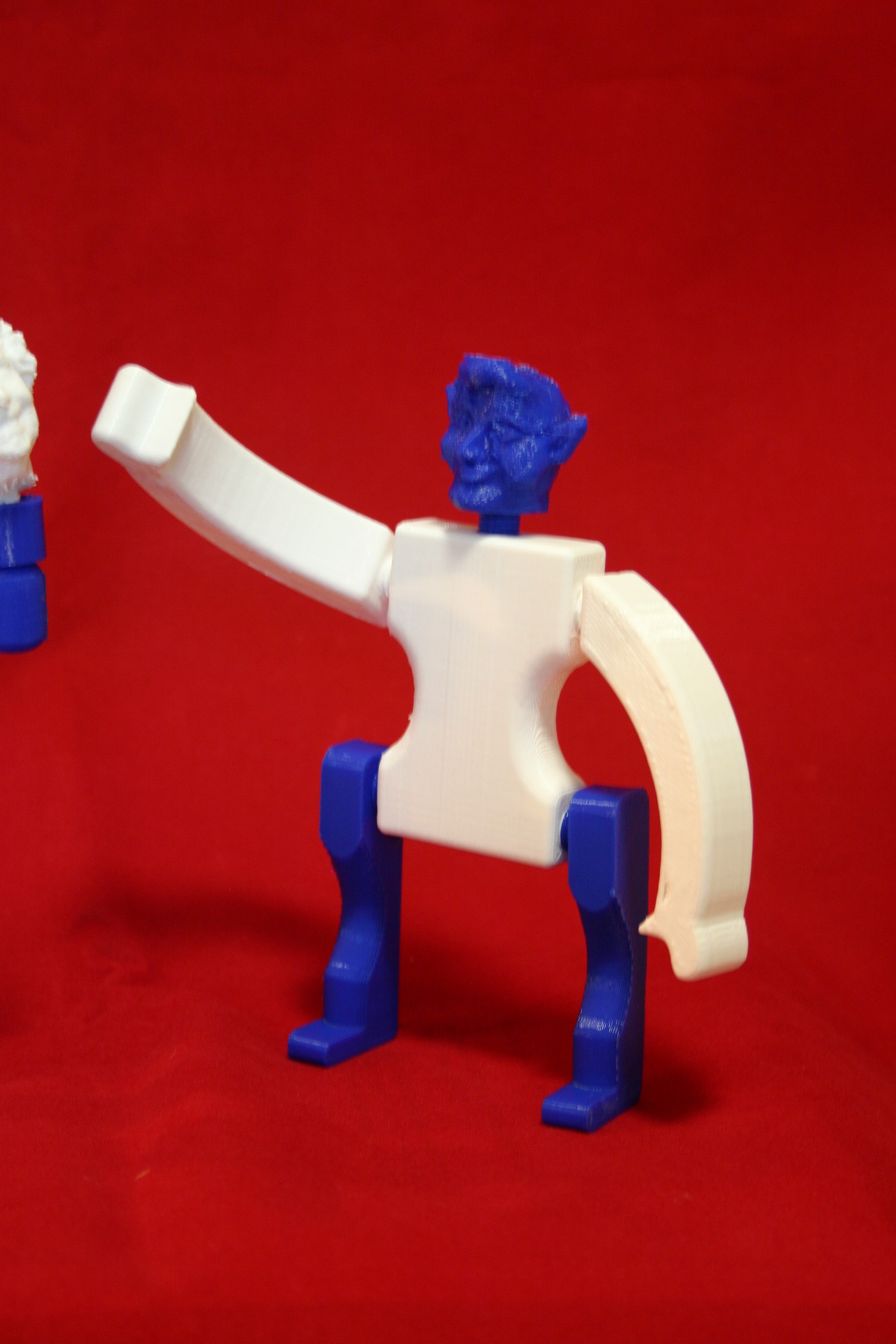
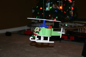
More Toys to Assemble
Method to Link Conveyor Belts
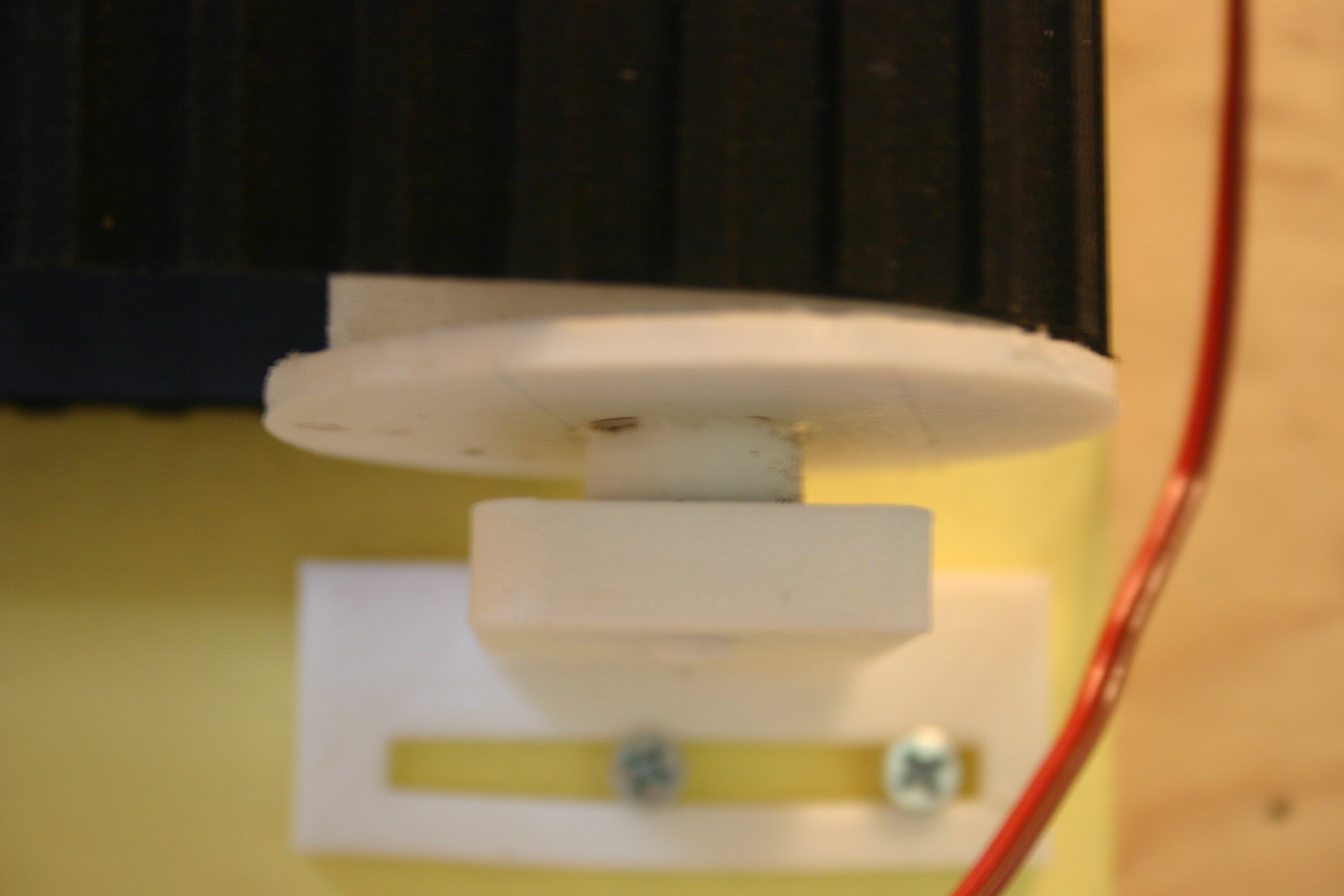
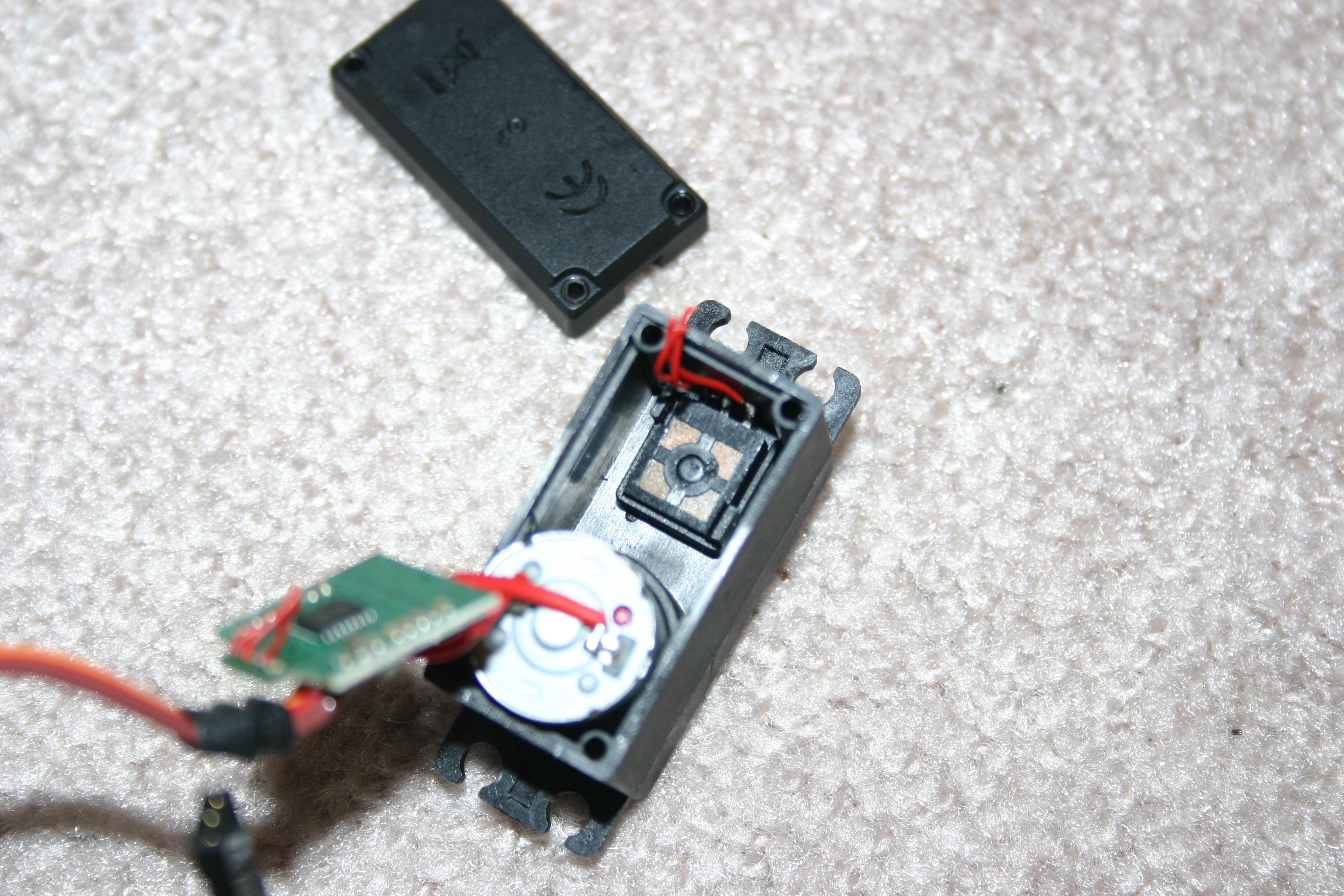
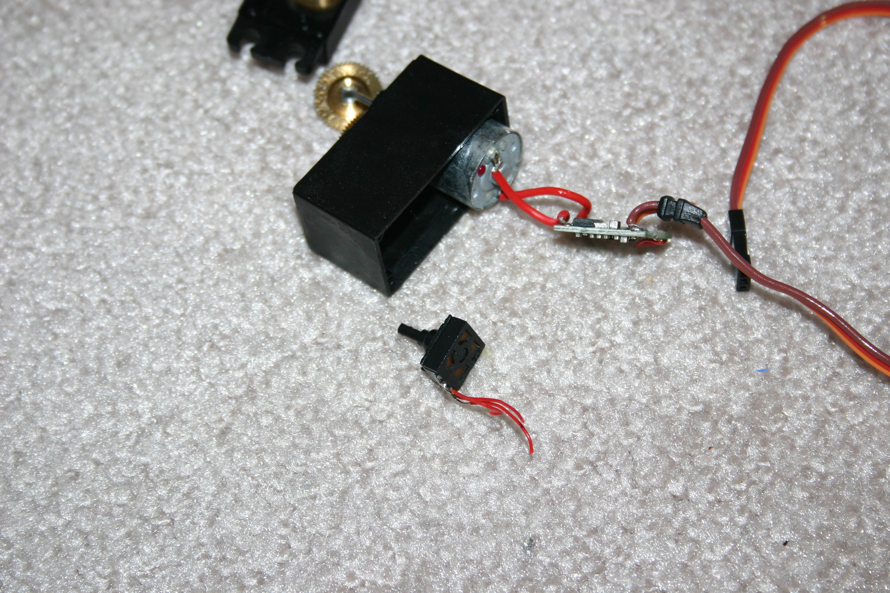
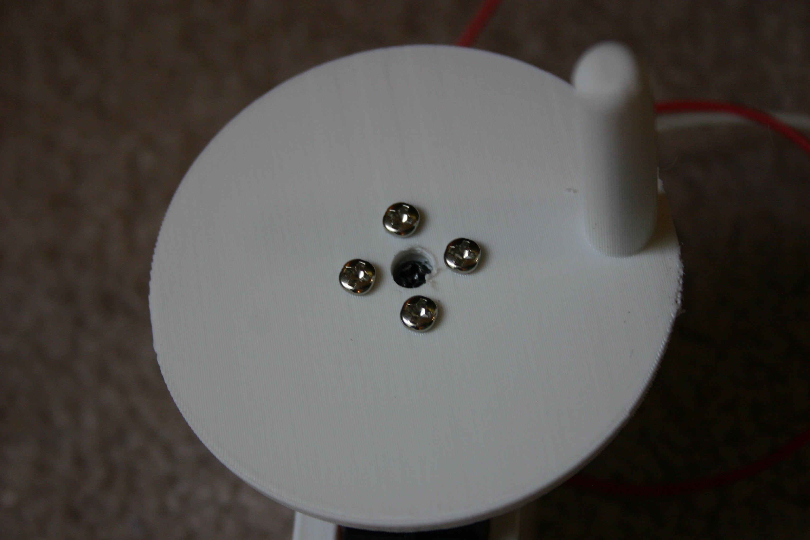
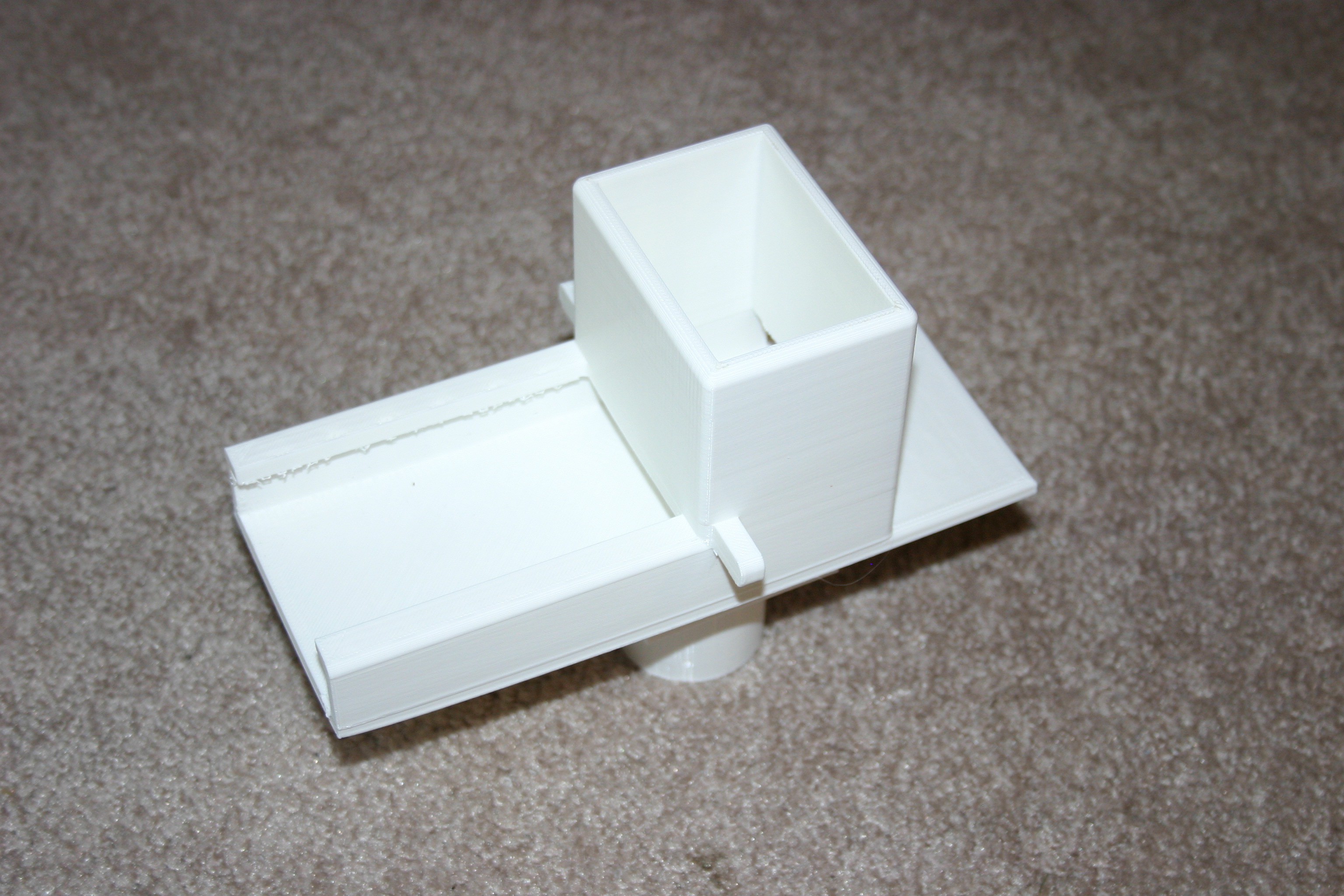
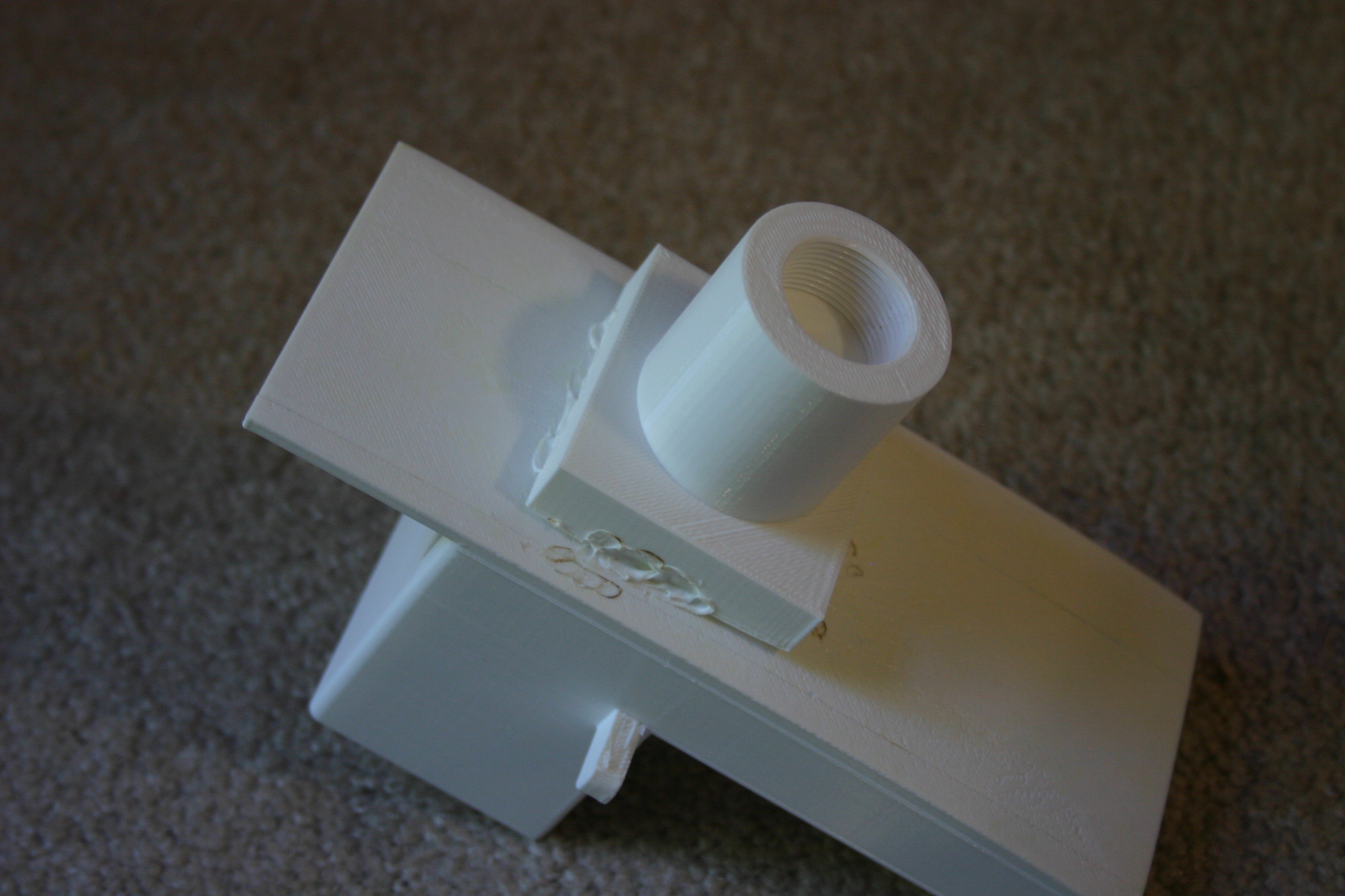
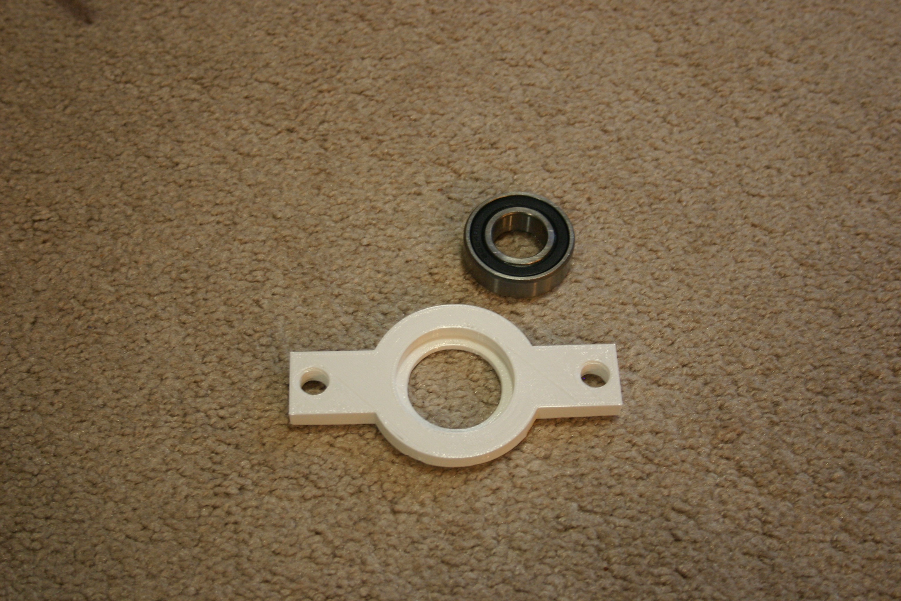
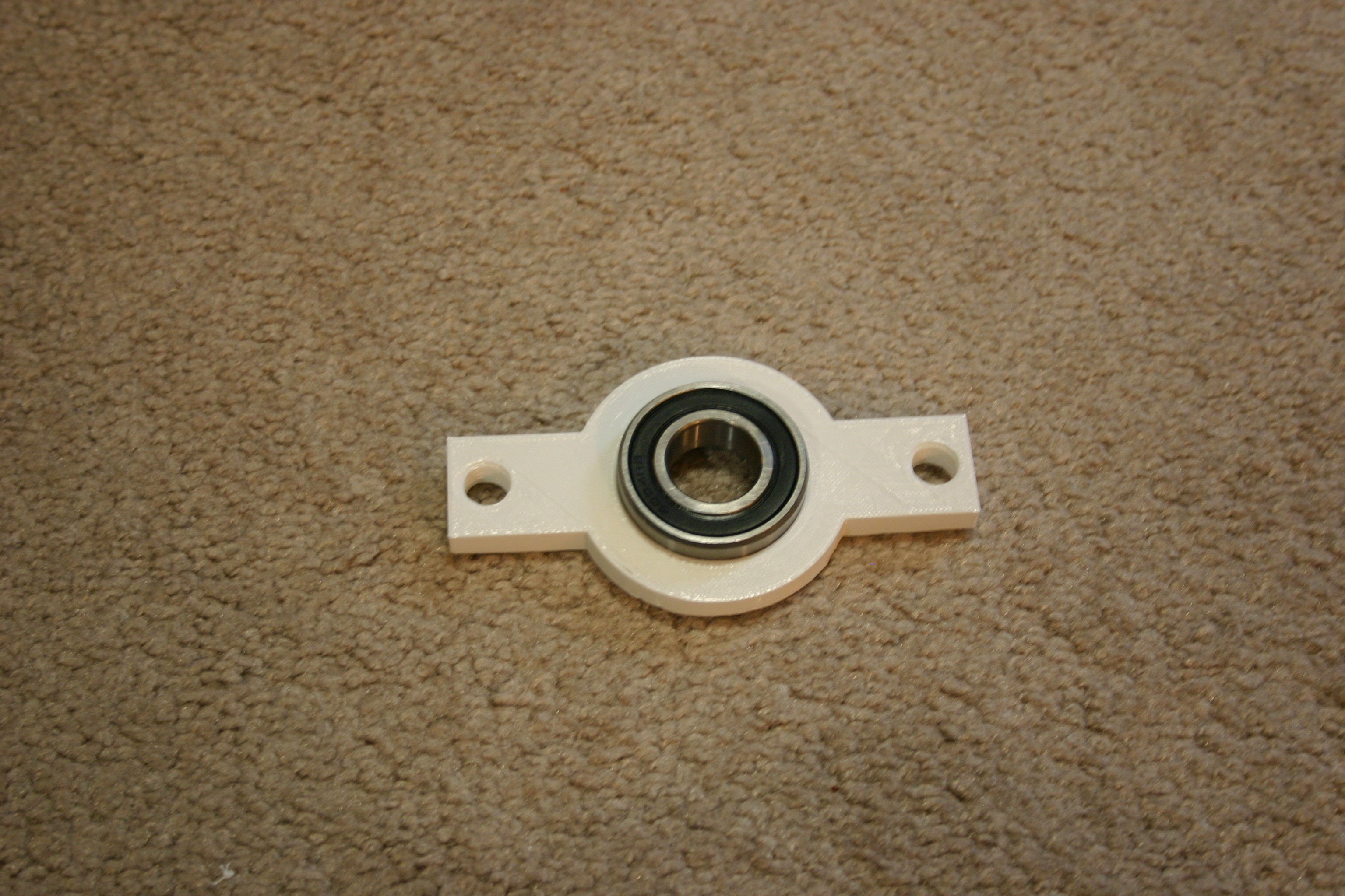
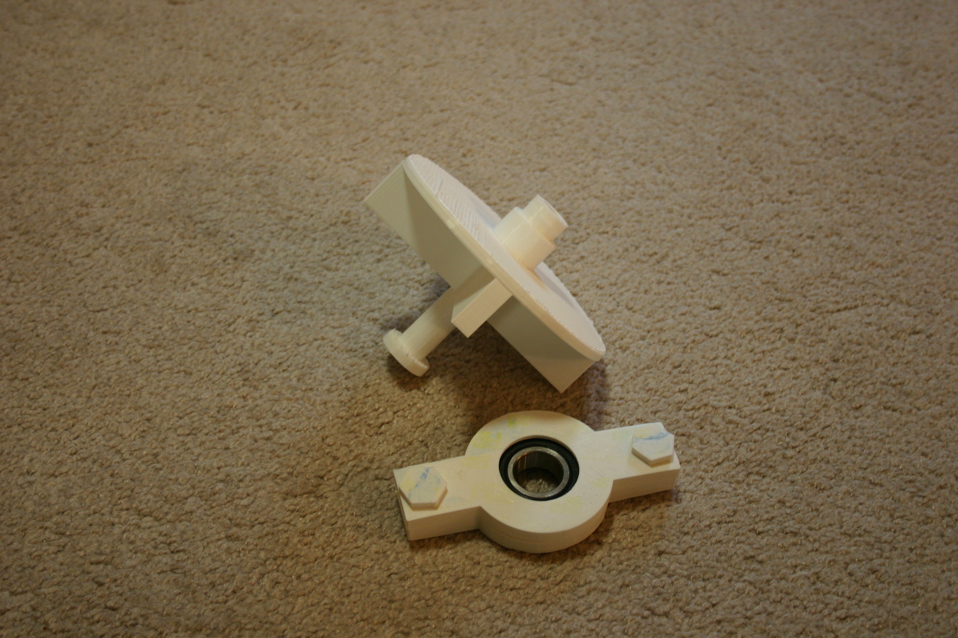
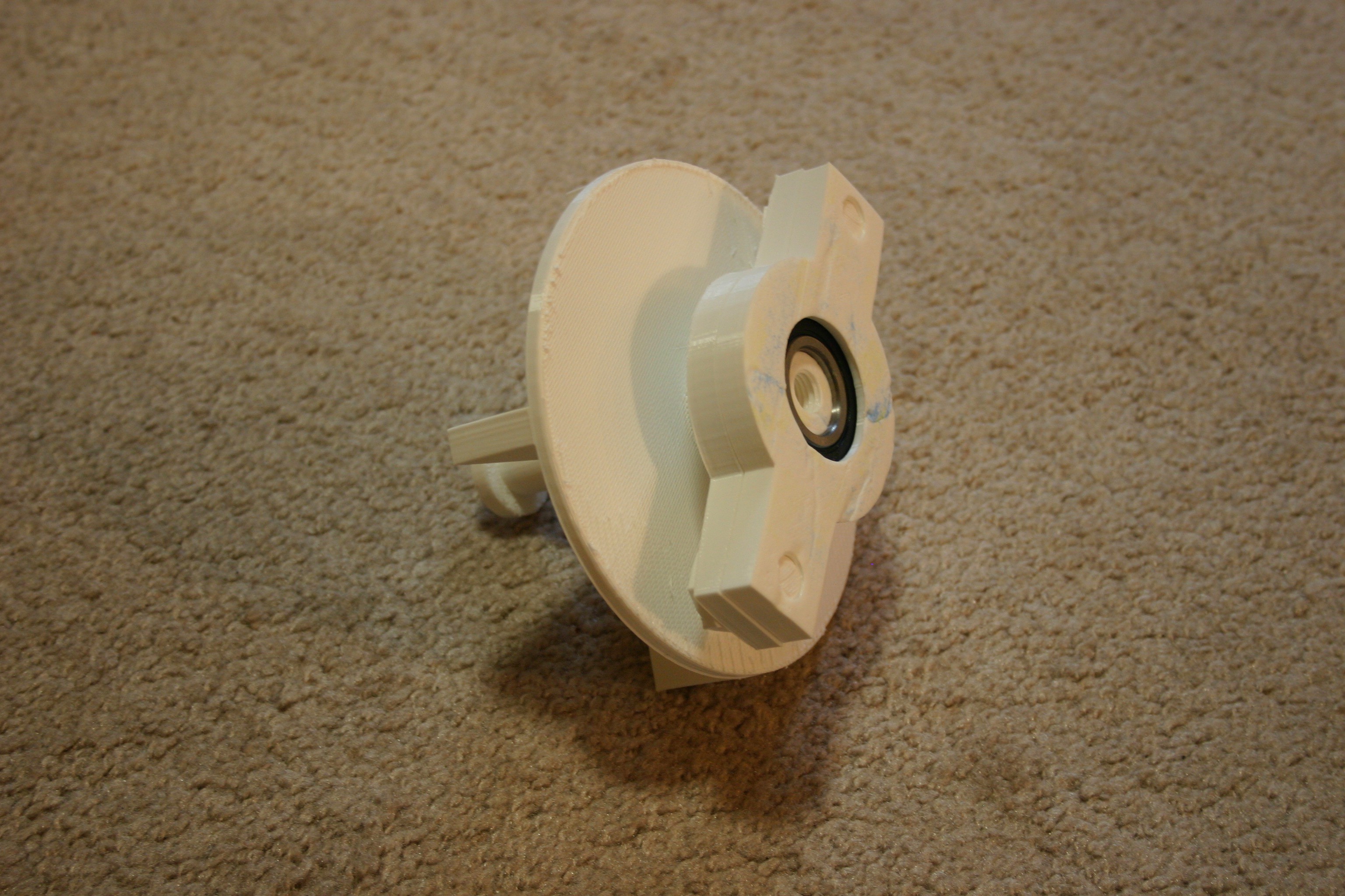
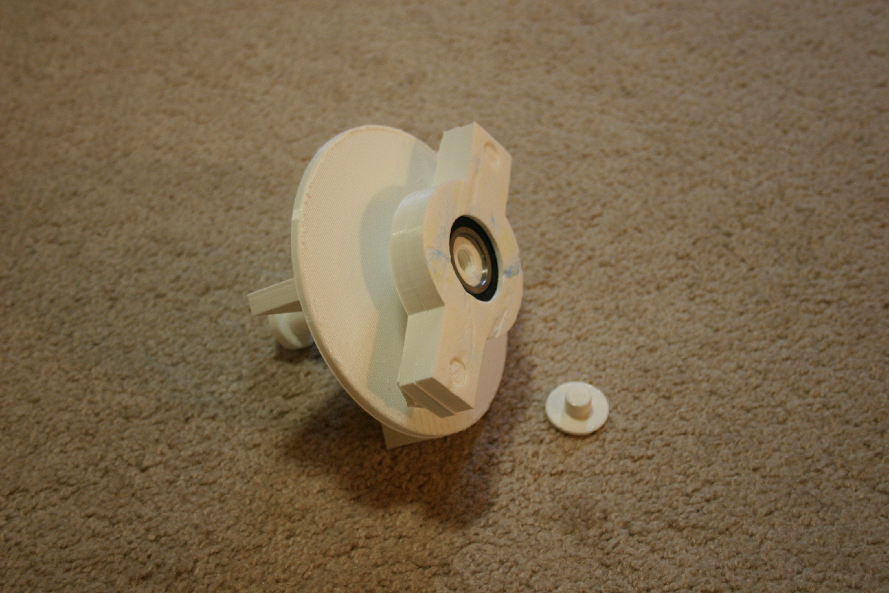
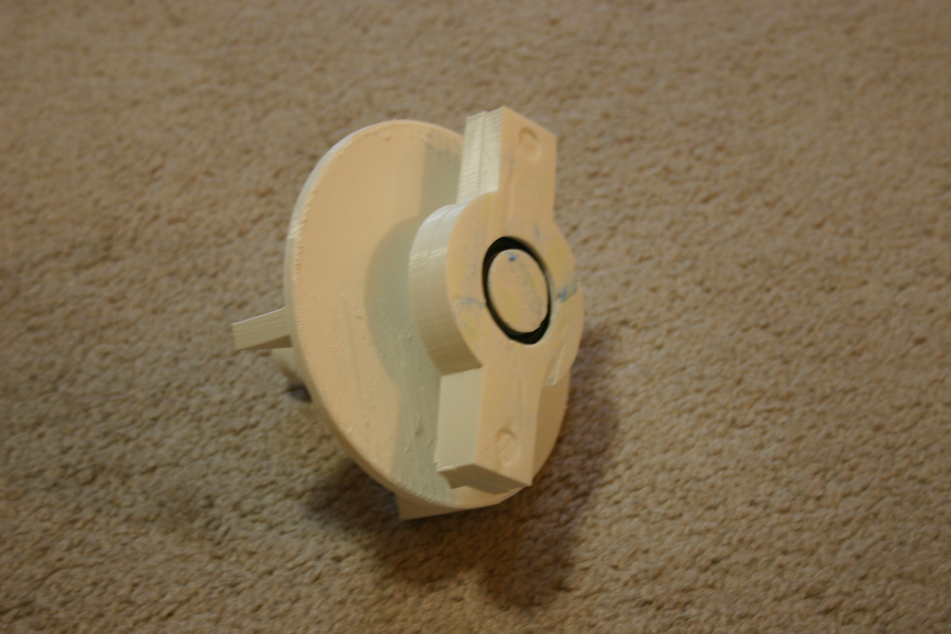
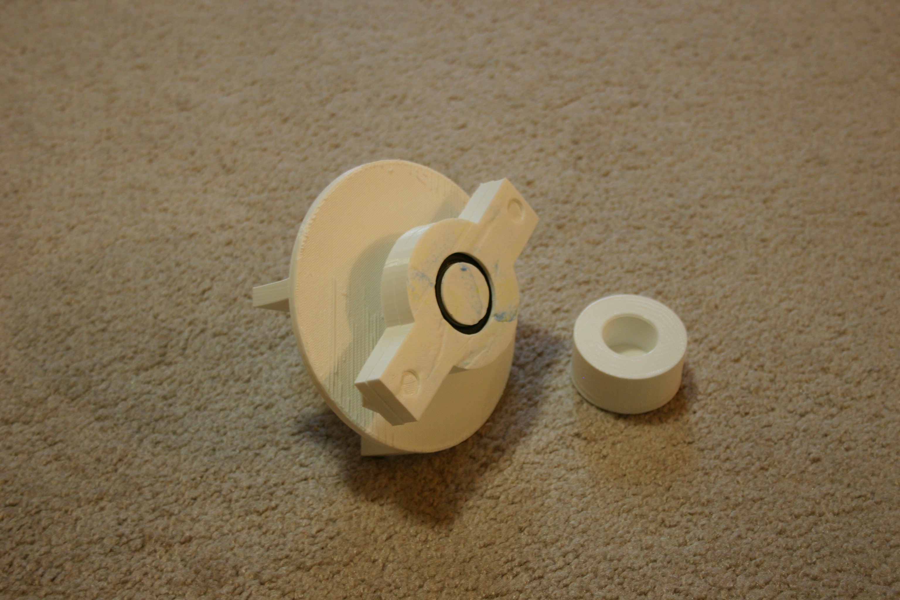
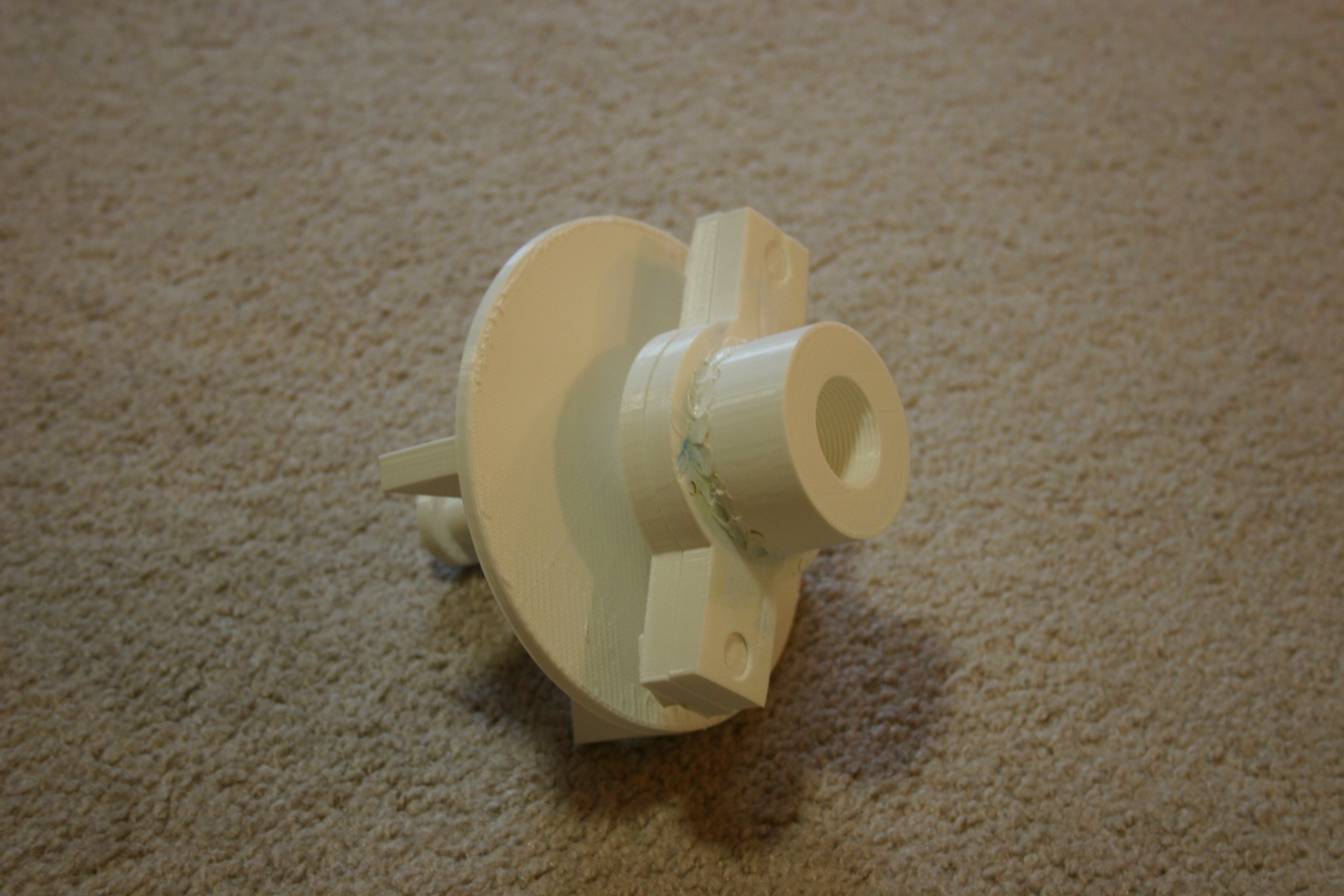
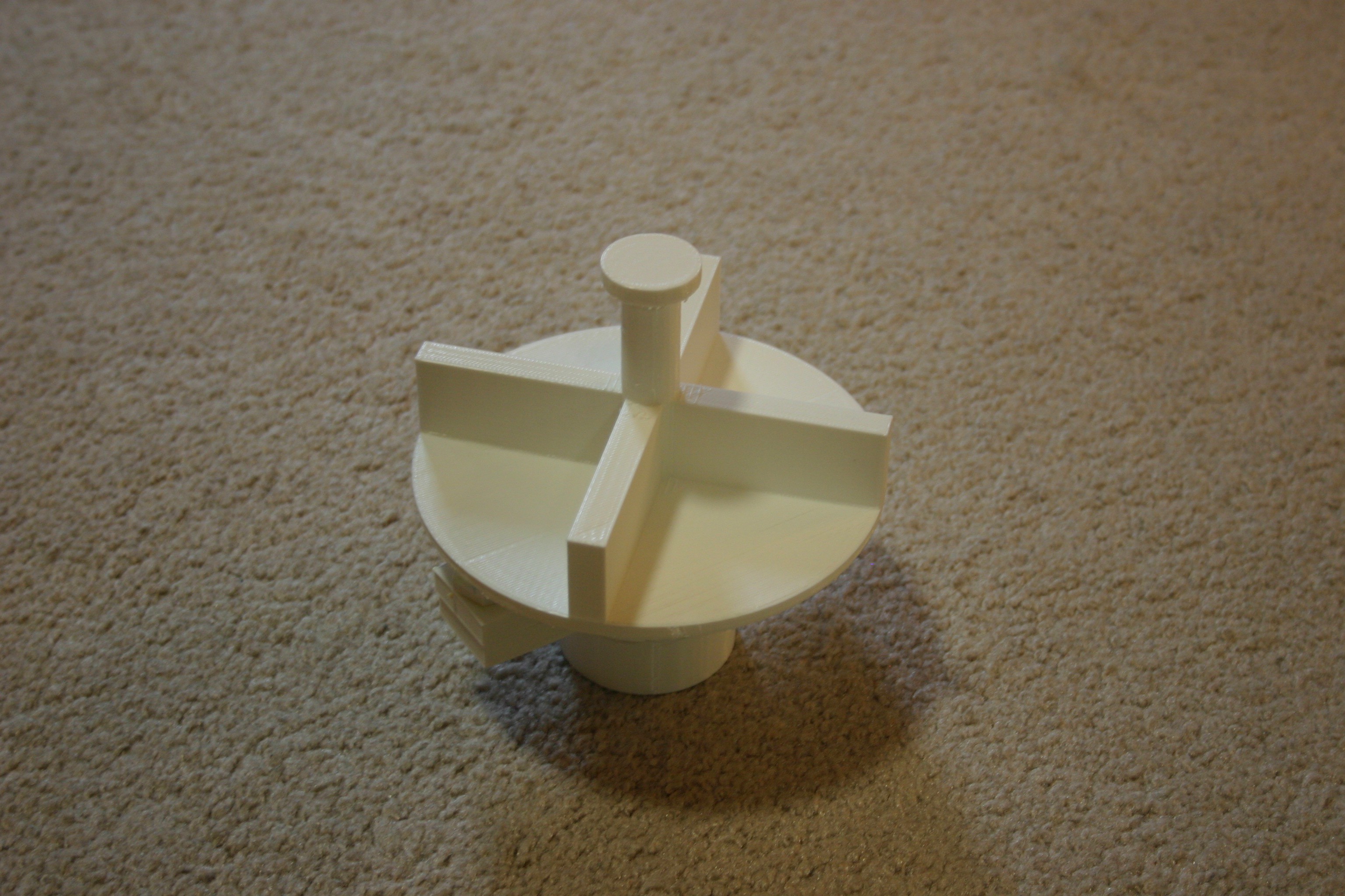
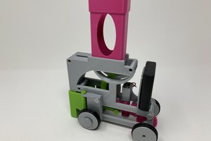
Now there is a rotating parts module in the first assembly position.
Here is a video of a super preliminary prototype.
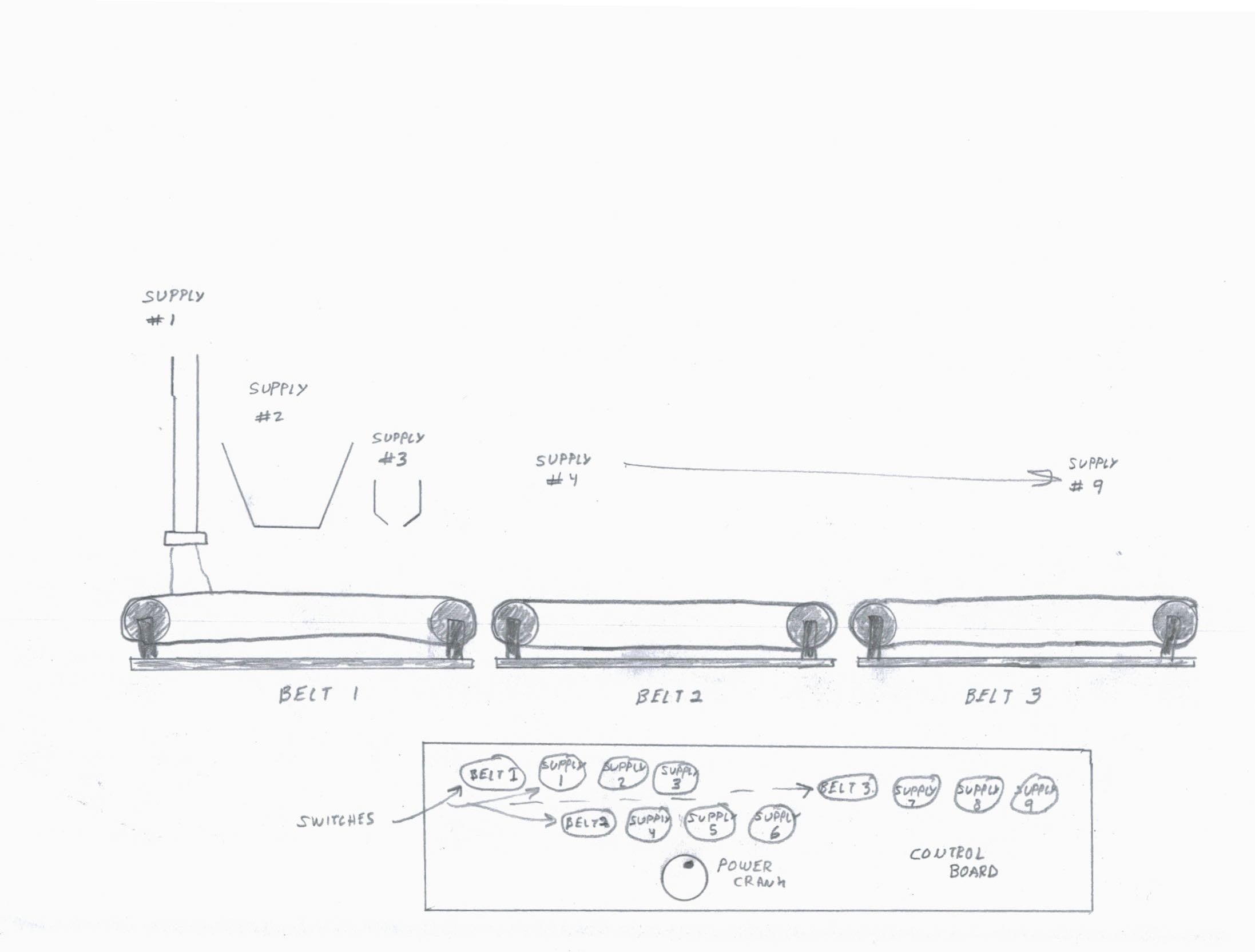
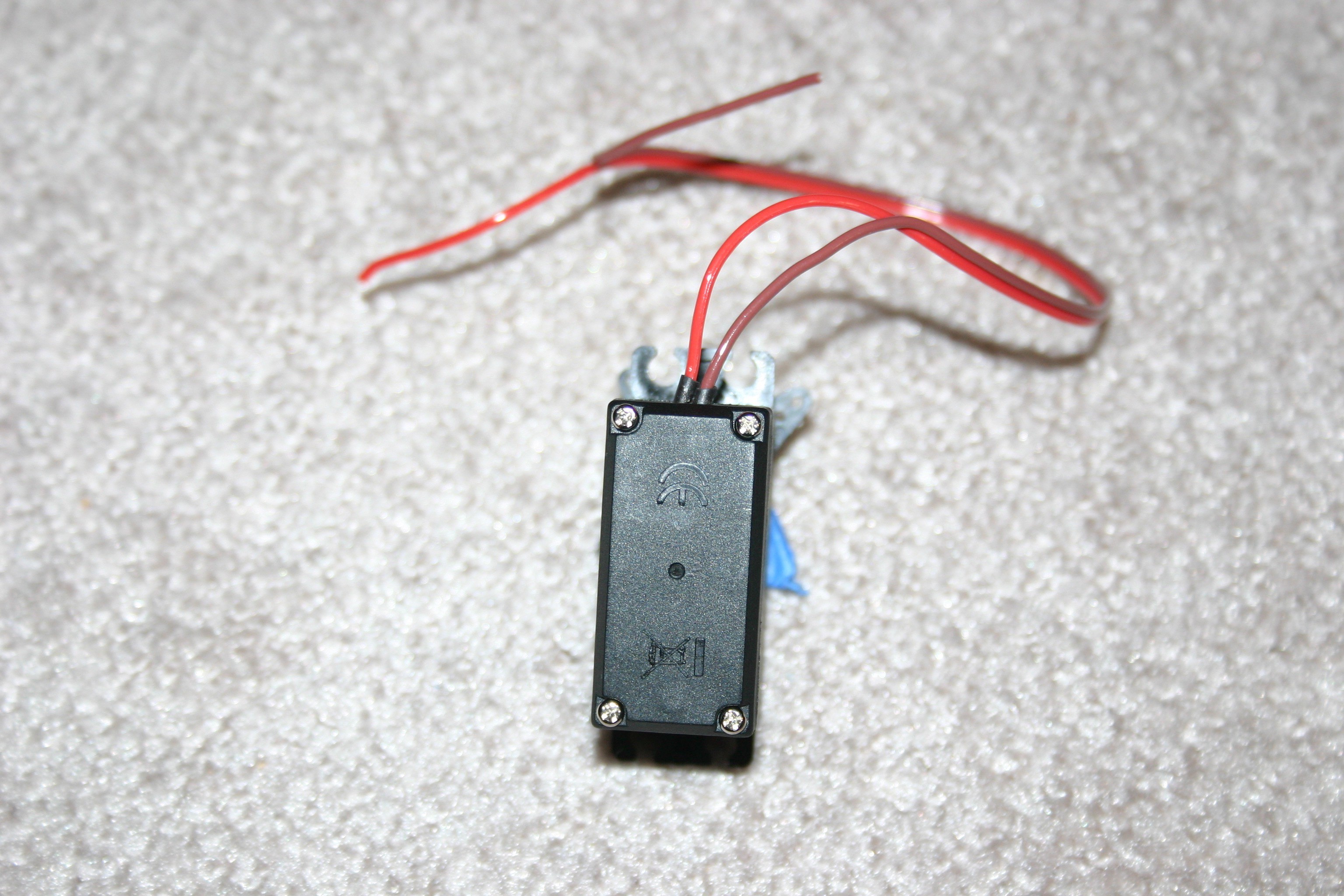
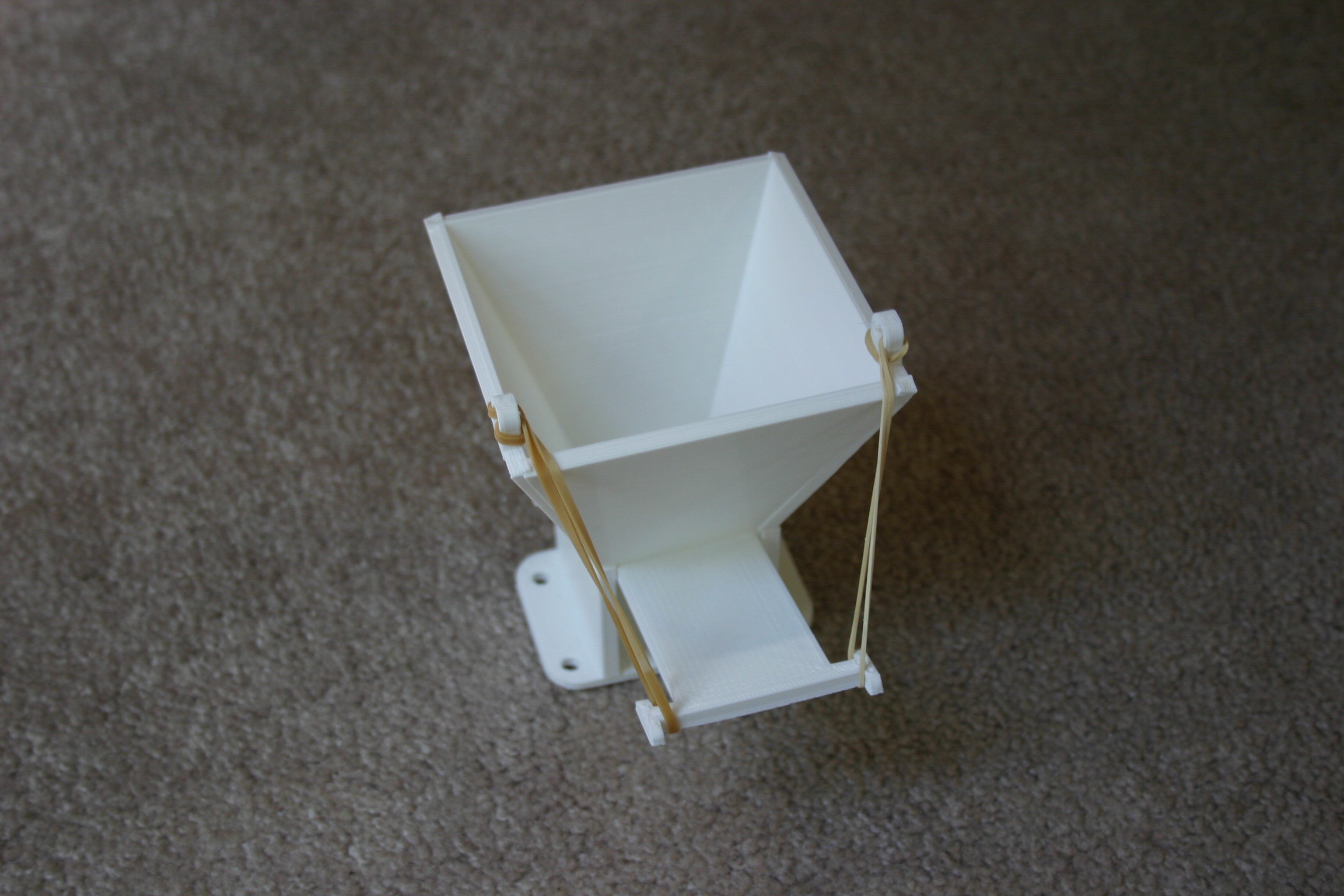
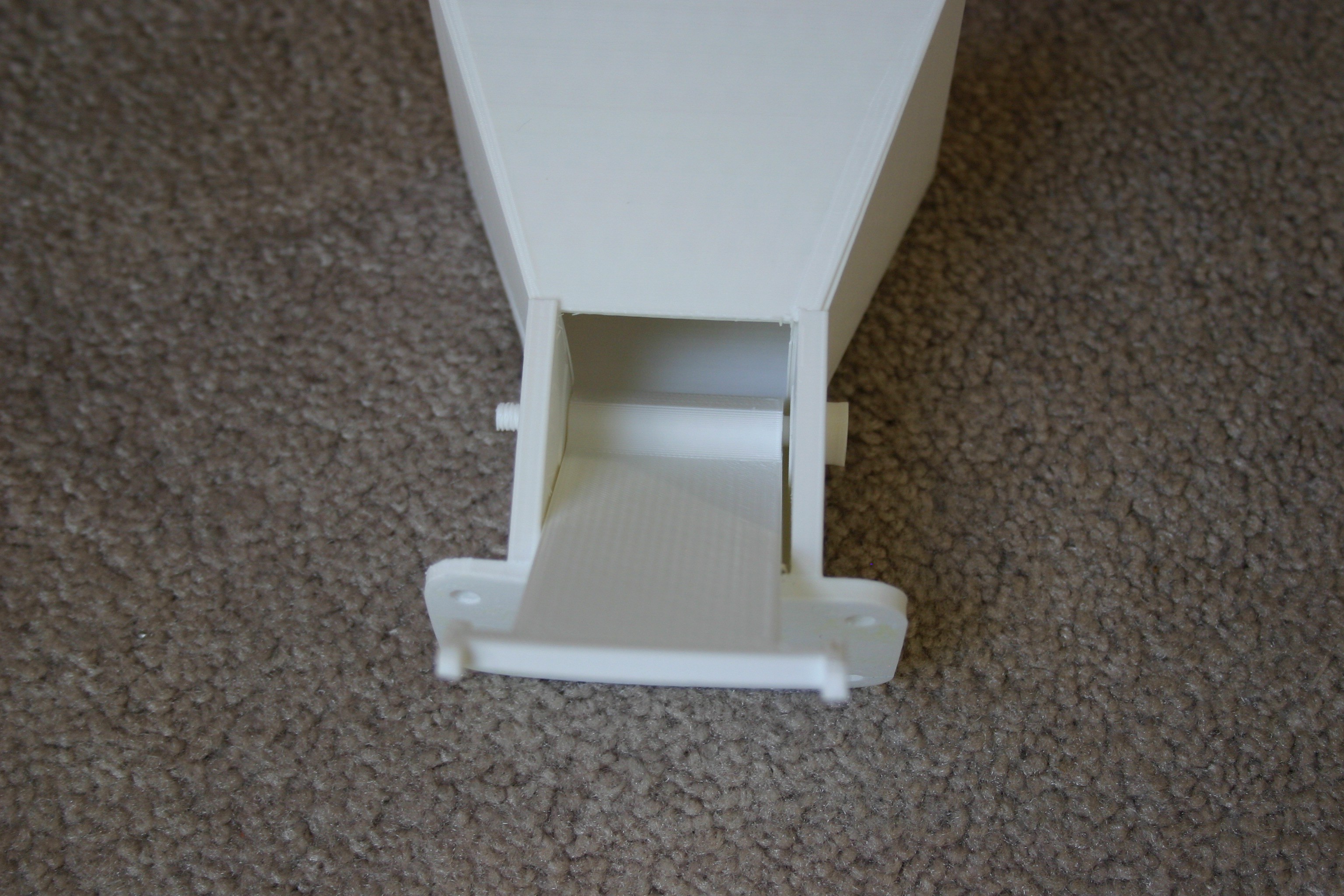
As a complete system, conveyor belts will be controlled by switches and powered by a hand crank generator. Supply bins will be manual or electric--electric being powered by the hand crank generator through switches. Supply bins will be modular and changeable. Similar to the old Lionel trains, the switches and modules can be wired by the user (kids) and they will learn about wiring and polarity.
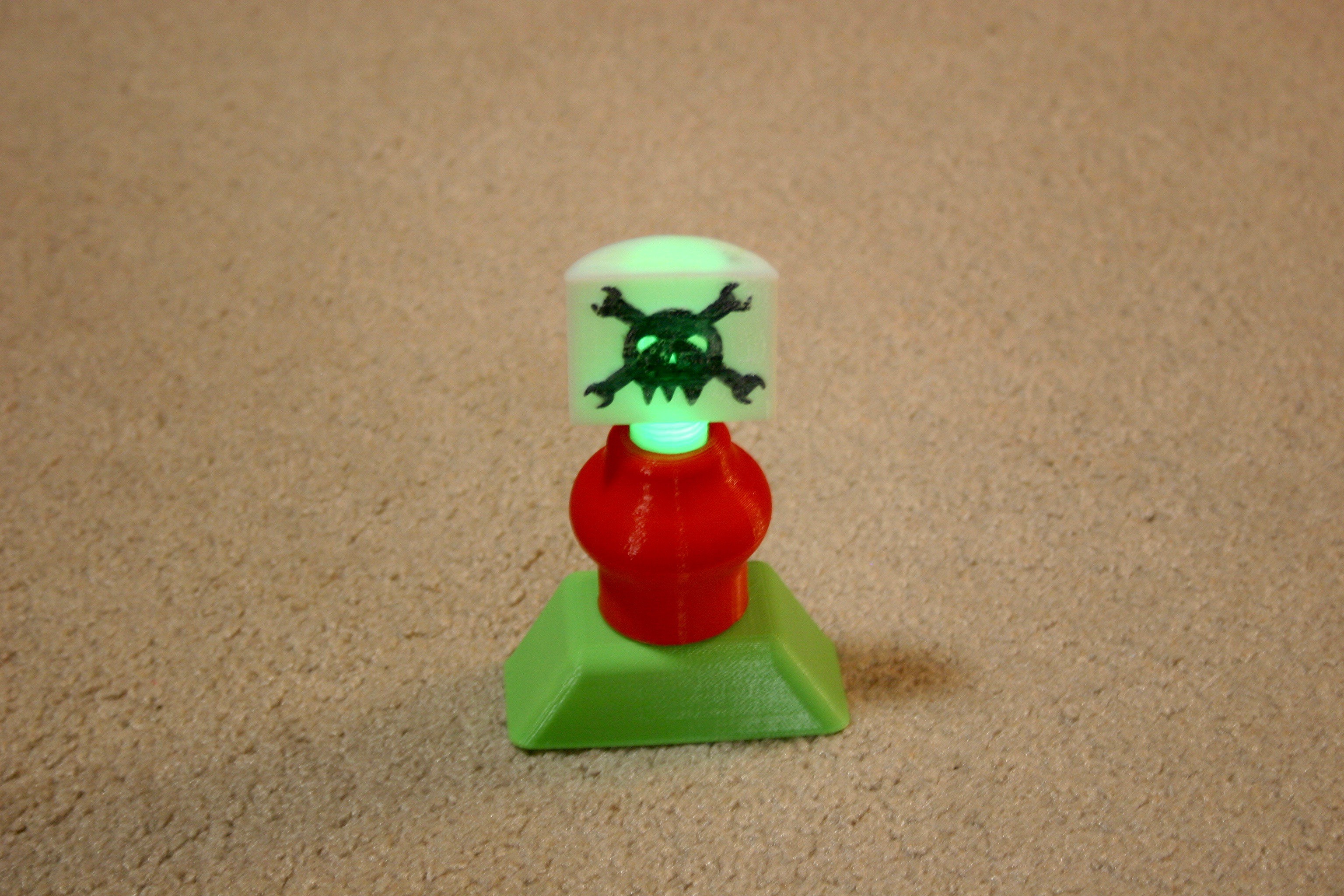
The first prototype makes use of a "Hackaday Bot" that can be found at Thingiverse.
The entire assembly can be placed on a play table.


 Greg Zumwalt
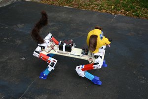

 gokux
gokux