Before we start I must warn you that if you're uncomfortable working on the mains side of a circuit, this project probably isn't for you. If you're open to learning and working with caution, proceed at your own risk. This modification isn't strictly necessary, so if you'd rather not take the risk, please don't. Electricity can harm and even kill you regardless of whether a device is unplugged. That said, I'm not an expert nor am I liable for any injuries or problems you may encounter, but I'll do my best to explain why I did what I did, answer questions, and make improvements and corrections from people who present sound evidence and reason. In fact, I just barely know what I'm doing - but I know just enough to not be dead, yet. Tell your family you love them before you proceed, especially if you're like me and inclined to teetering on the edge of stupidity.
If you haven't picked up on it, I like to err on the side of too much information. Explaining the context around things helps me understand, especially when I'm new to something, and it might help you as well - but if that's not your cup of tea, you can jump directly to the how-to areas:
- Testing your wiring
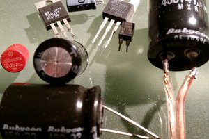
- Inspecting capacitors (coming soon)
- Adding a switch
- Becoming more patient
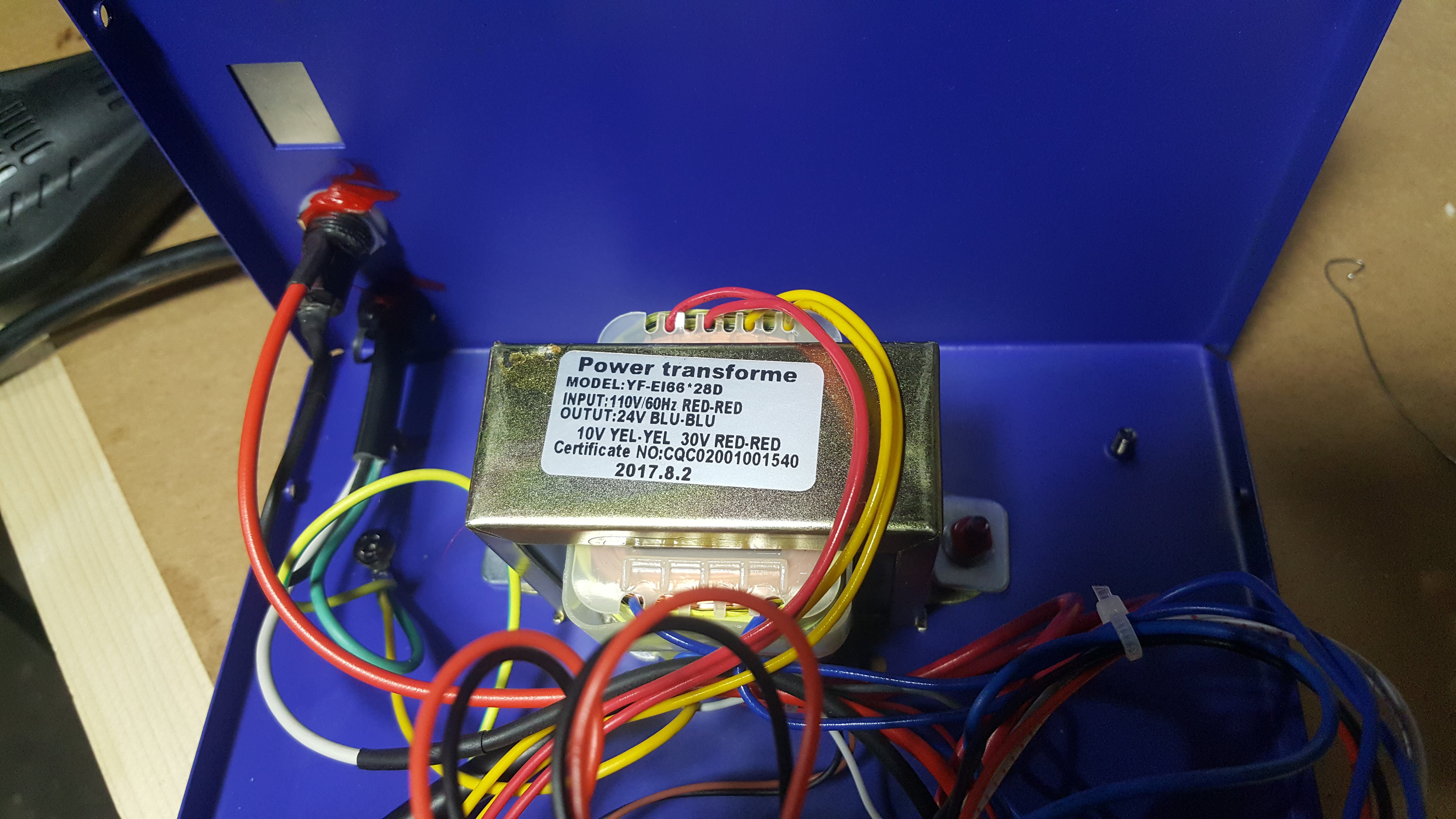
Several months ago, I bought an 862D+ station. My research prior to this purchase suggested that this unit is some sort of clone (the original possibly being Yihua or Hakko?) proliferated by numerous vendors and/or manufacturers. Early models had their fuses and switches connected to neutral, which is a safety issue because a short won't trip the fuse until well after the circuit is hazardous. Youtuber Tinkering with Terrius did a solid teardown and review and also a fix video for models that have a mains switch. Later models are reported to be wired correctly. If you have more info on any of this, I'm curious to know.
My station has a front panel-mounted switch for each of the soldering tools - but was missing the mains switch I had seen on other units - so the PSU was constantly on. I suspected this when I could still hear a faint hum from the unit after powering down the hot air circuit.
The user manual was well-written enough to discern that the hot air gun's fan stays on after its circuit is powered down. I found more evidence toward this when I unplugged the unit and the indicator LED - which had been off - lit up and then slowly faded due to a capacitor discharging.
In short, the only way to fully power this thing down was to unplug it. That's unacceptable to me, so I decided to add a mains switch. Before doing that, I decided to first test if the fuse was wired to hot and not neutral.
When I opened the case, I was amused to find a perfectly sized hole exactly where I would've expected the mains switch. This was covered with a specifications sticker from the outside. Sneaky buggers. At least I don't need to cut the hole myself.
To test if your unit (without a mains switch) is wired correctly:
- If it's plugged in, unplug it and give it time for the capacitors to discharge according to the value of the resistor across the capacitor, if there is one at all. If not, consider researching how to safely discharge capacitors. No, a screwdriver across the terminals isn't acceptable. No, I don't care how low the voltage or how insulated your screwdriver is. I'll document the particulars of my unit in more detail later.
- Set your DMM to continuity and set your preferred indicator. Some DMMs make an audible beep or will show a resistance. Refer to your DMM's manual for how to do this. You can test that your meter is working by simply touching the probes together - if your indicator signals, you're good.
- Plug your black probe into ground/common and your red probe into whatever your DMM's continuity setting input requires, usually V/Ω/Hz.
- Take out your 862D+'s fuse and put it in a safe place. Mine is a 6A 5x20mm glass fuse housed...
 Arya
Arya
 kristina panos
Great write up! Convinced me to get one, and then to doulbe check the wiring.
I found this DPST illuminated power switch on Amazon:
https://www.amazon.com/gp/product/B07QQ217DY/ref=ppx_yo_dt_b_asin_title_o00_s00?ie=UTF8&psc=1
Perfect size! Wired one side of the switch after the fuse for the AC line voltage.
On the other side of the switch I wired in the AC neutral voltage.
Again thanks for the write up.