 AVR
AVRAudio Blox is where I will be publishing everything related to my analog audio design experiments and learning experience. Experiments/Designs that go well will be spun off into their own projects while others will live and die on this page.
Projects So Far:
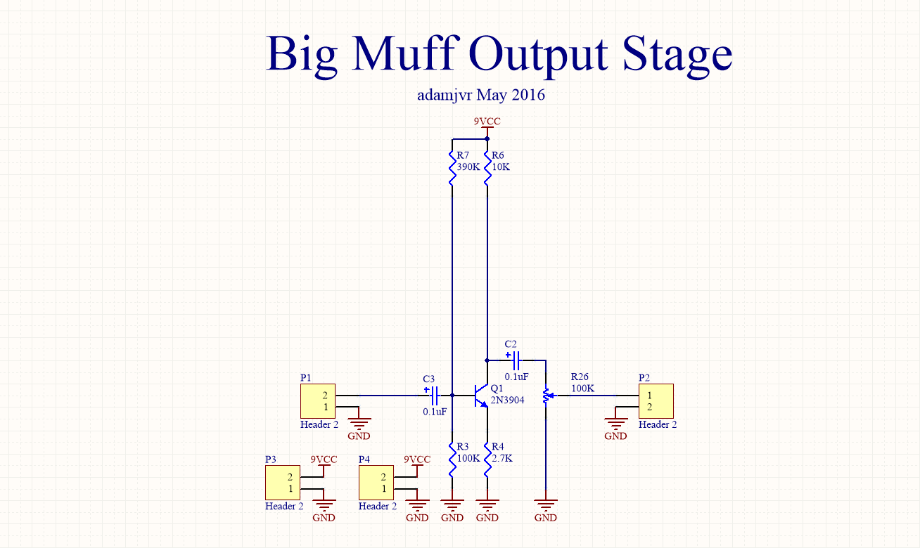
Big Muff Blox
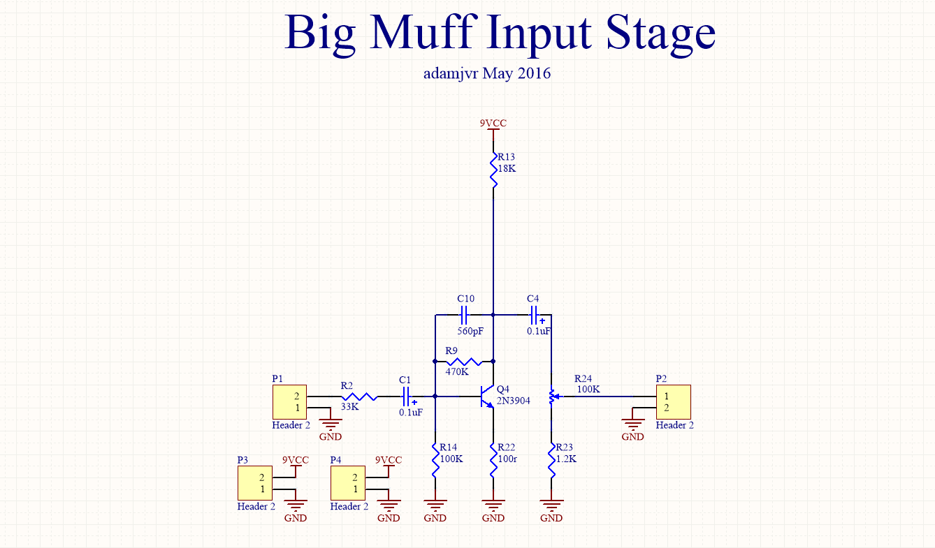
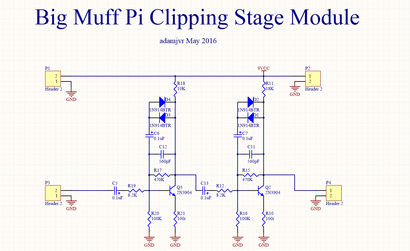
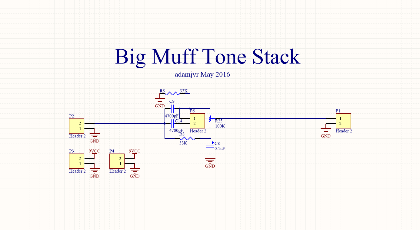
Big Muff Blox will be 4 PCBs deividing the Big Muff pedal circuitry across four PCBs. The PCBs will be design to plug into a breadboard for testing, experimenting, and analysis.
Boards Broken down to:
- Input Stage
- Clipping Stages (both on one PCB)
- Tone Stack
- Output Stage
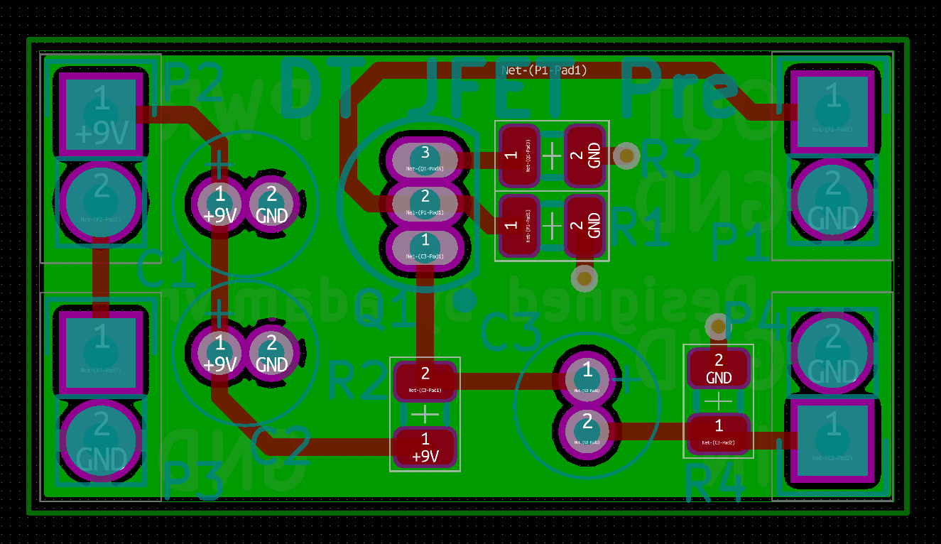
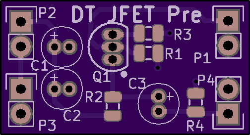
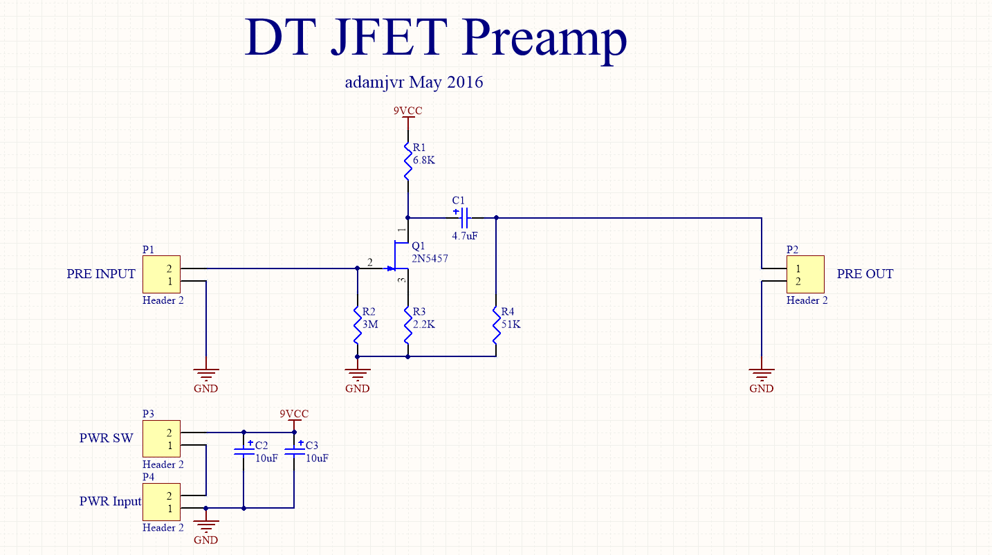
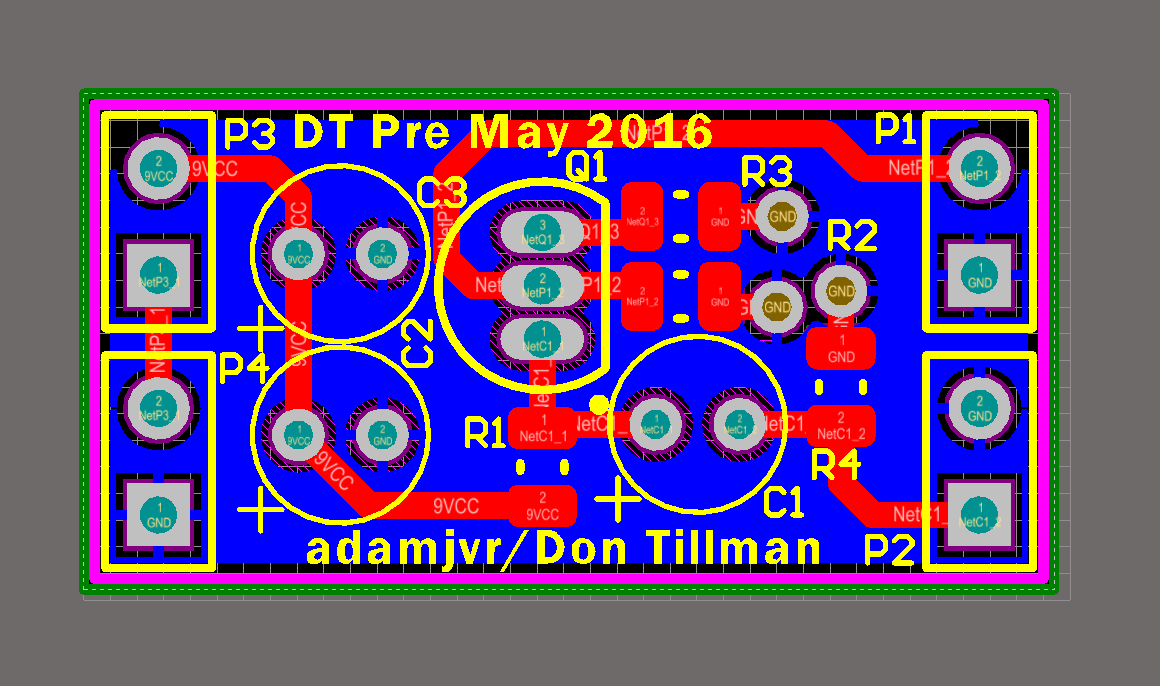
Don Tillman JFET Preamp
Simple PCB implementation of the popular JFET guitar preamp designed by don Tillman. It will be a simple PCB with inputs for power, and connections for signal input and output.

Credit to Don Tillman for his design, nice website: http://www.till.com/articles/GuitarPreamp/
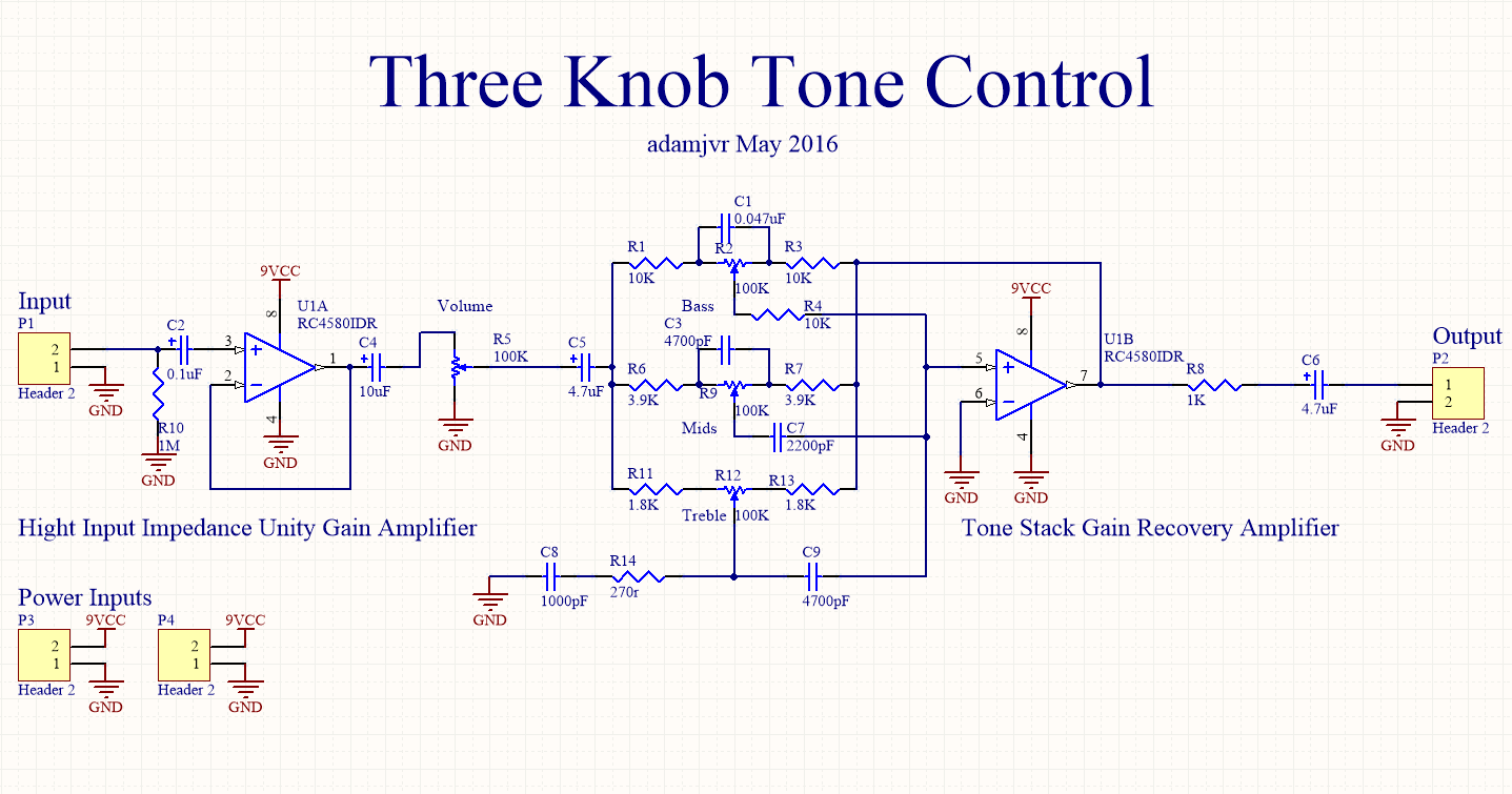
Treble , Mid, Bass Active Tone Control Block
This project is a bit more complex. Eventually some of these designs are going to need tone control. This project is my attempt to make an active tone control circuit based on this random schematic I found:
http://www.eleccircuit.com/three-circuits-of-preamp-tone-controls-by-ne5532/
PCB Route Pass 1:
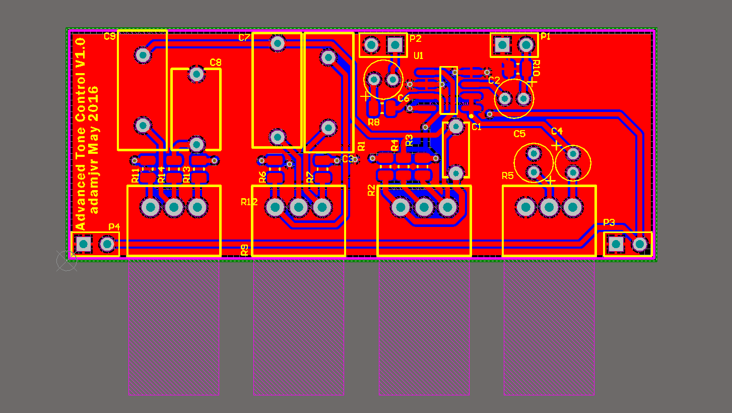
The plan is to start by building a mono channel tone control based on the circuit but adjusting the values for the electrical guitar's frequency response.
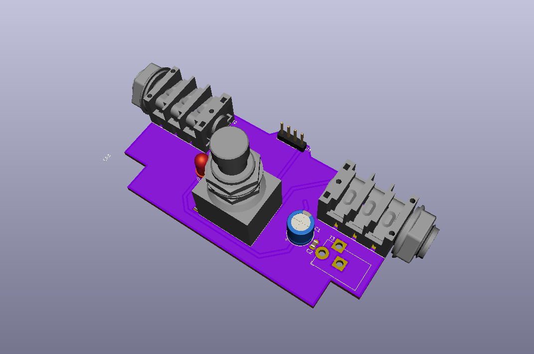
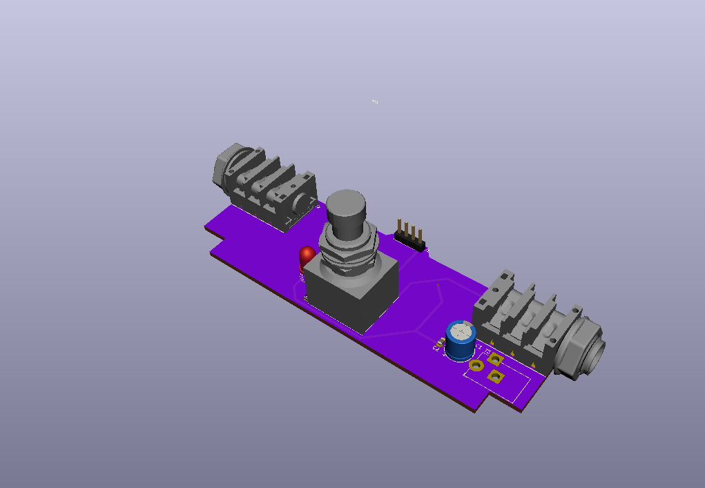
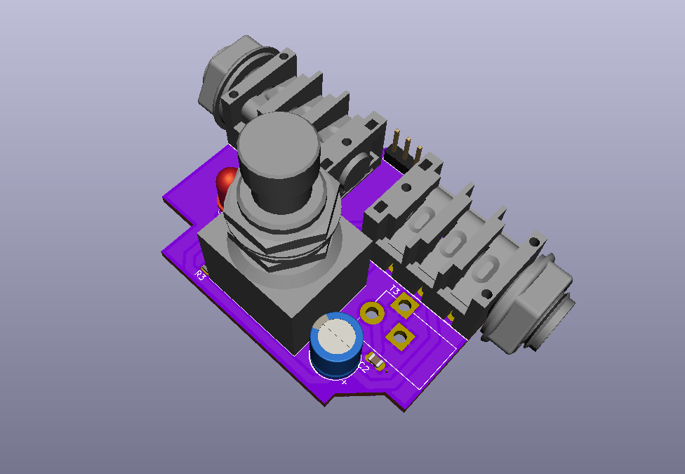
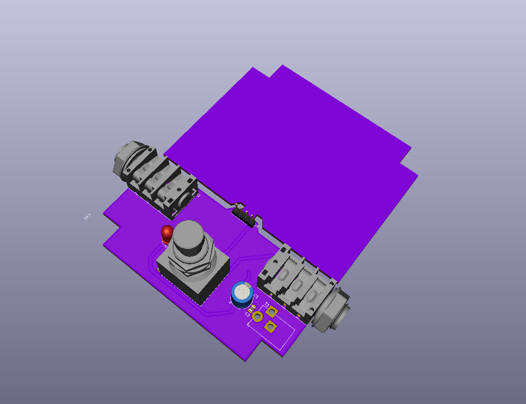
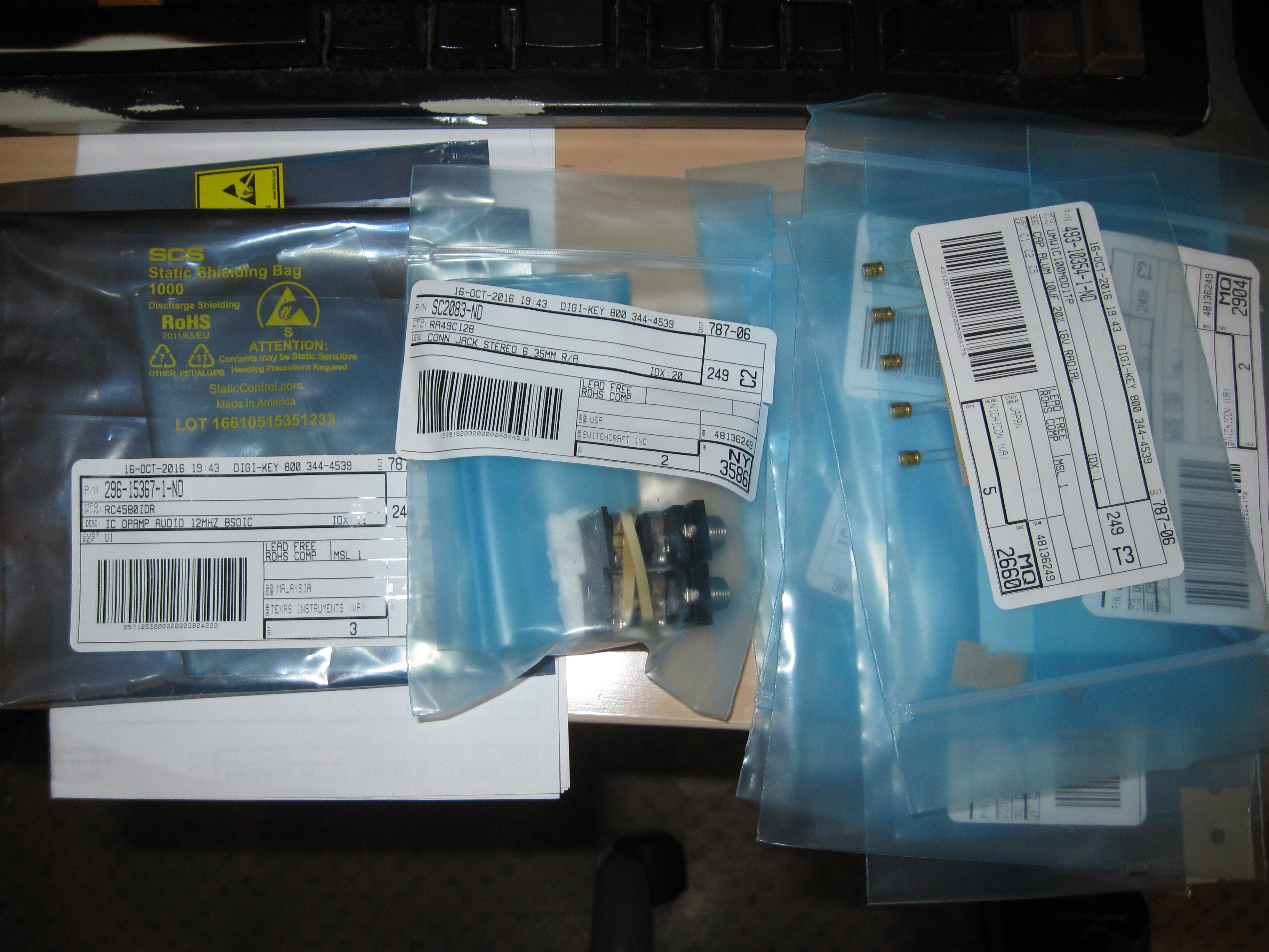
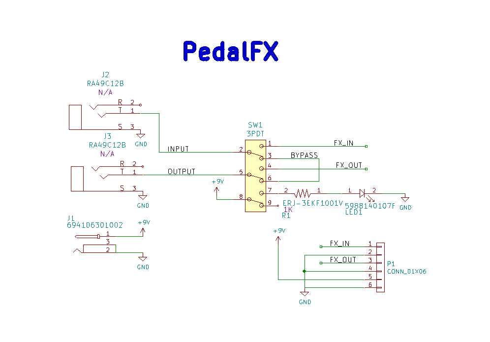
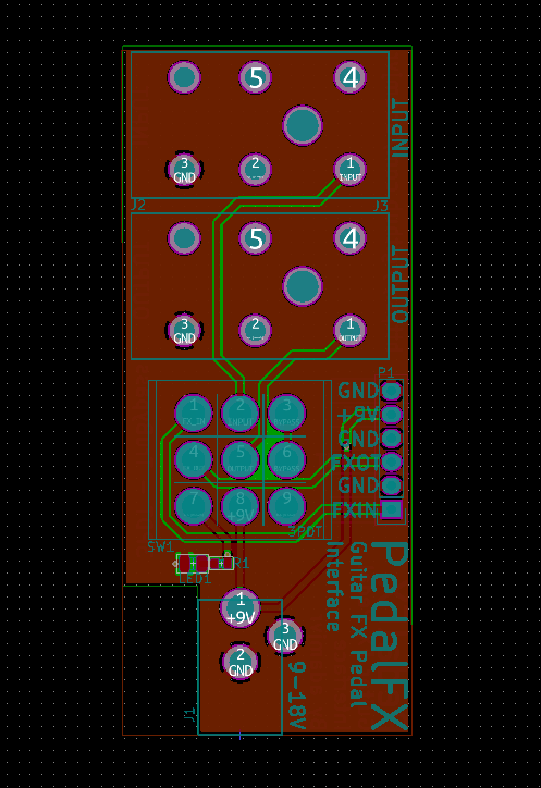
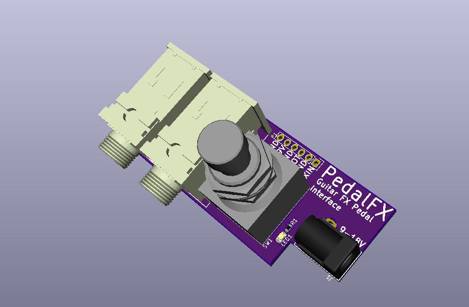
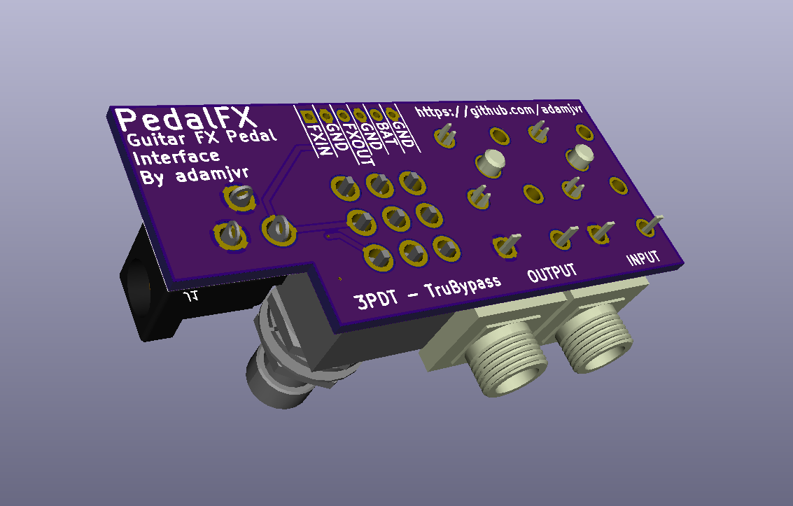
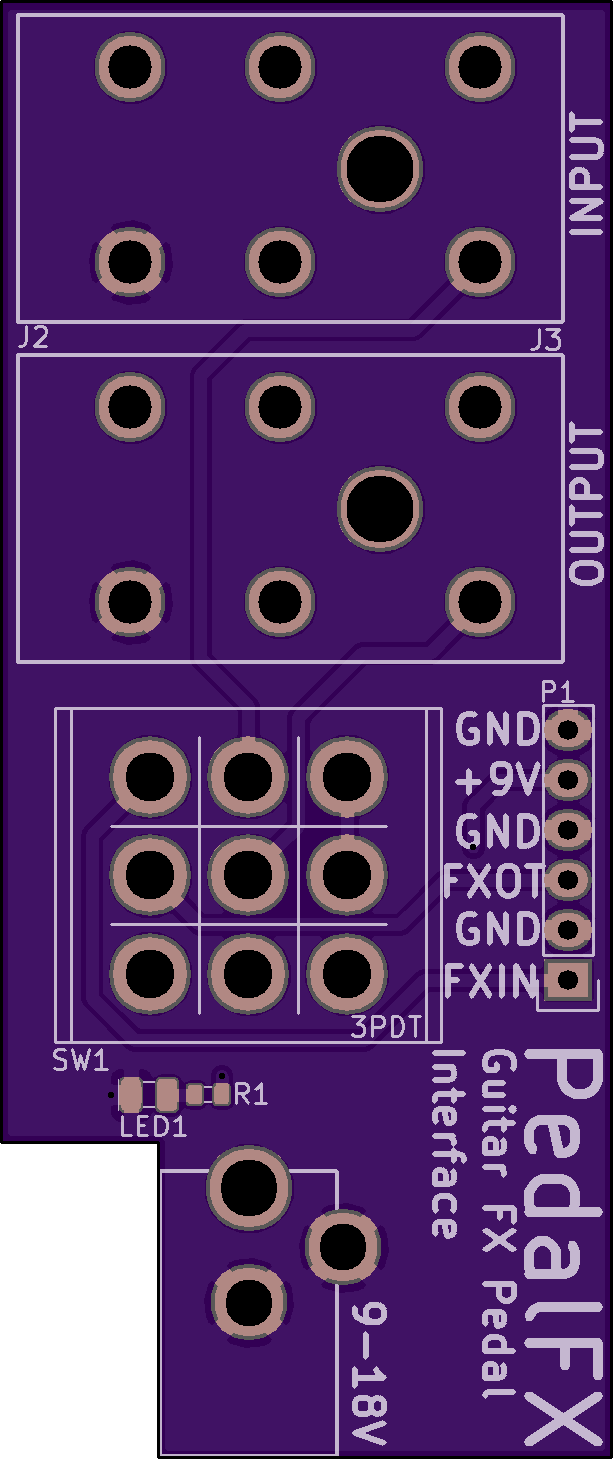
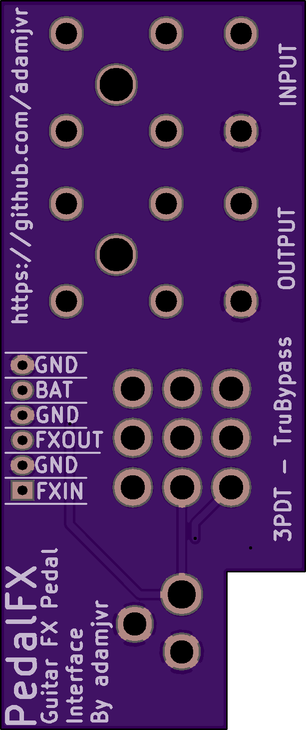
Guitar FX Pedal Wiring Board
Newest project is a simple board for wiring up guitar FX pedals. The circuit and design are from mysticwhiskey on the madbean pedal forum http://www.madbeanpedals.com/forum/index.php?topic=3308.0 . Its a simple design that consists of a pair of 1/4 TRS jacks, a 3P3T switchm and an LED for power. I'm simply making my own version of the PCB that I can just order at will for my own projects.
Mysticwhiskey's design![]()
Cousin Projects:
PiModulos - Custom Big Muff Pi w/ Mods PCB
A Custom PCB for implementing many variants of the Big Muff Pi Fuzz pedal with the options for some popular mods, initial prototype inspired by Skreddy Mayonnaise.
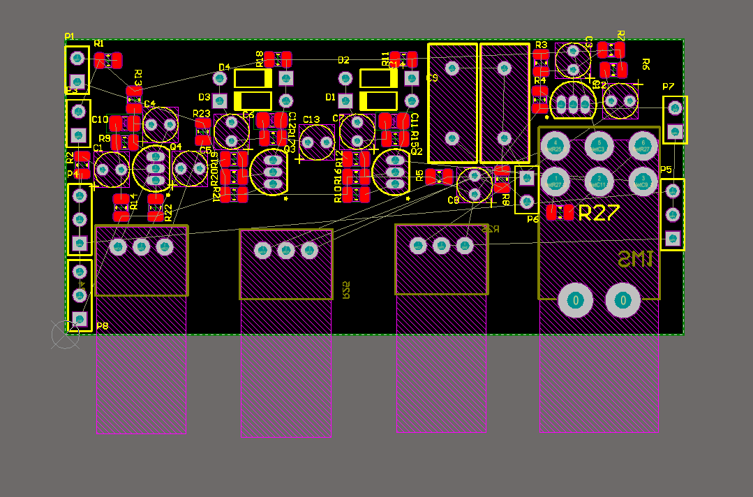
https://hackaday.io/project/7840-pimodulos
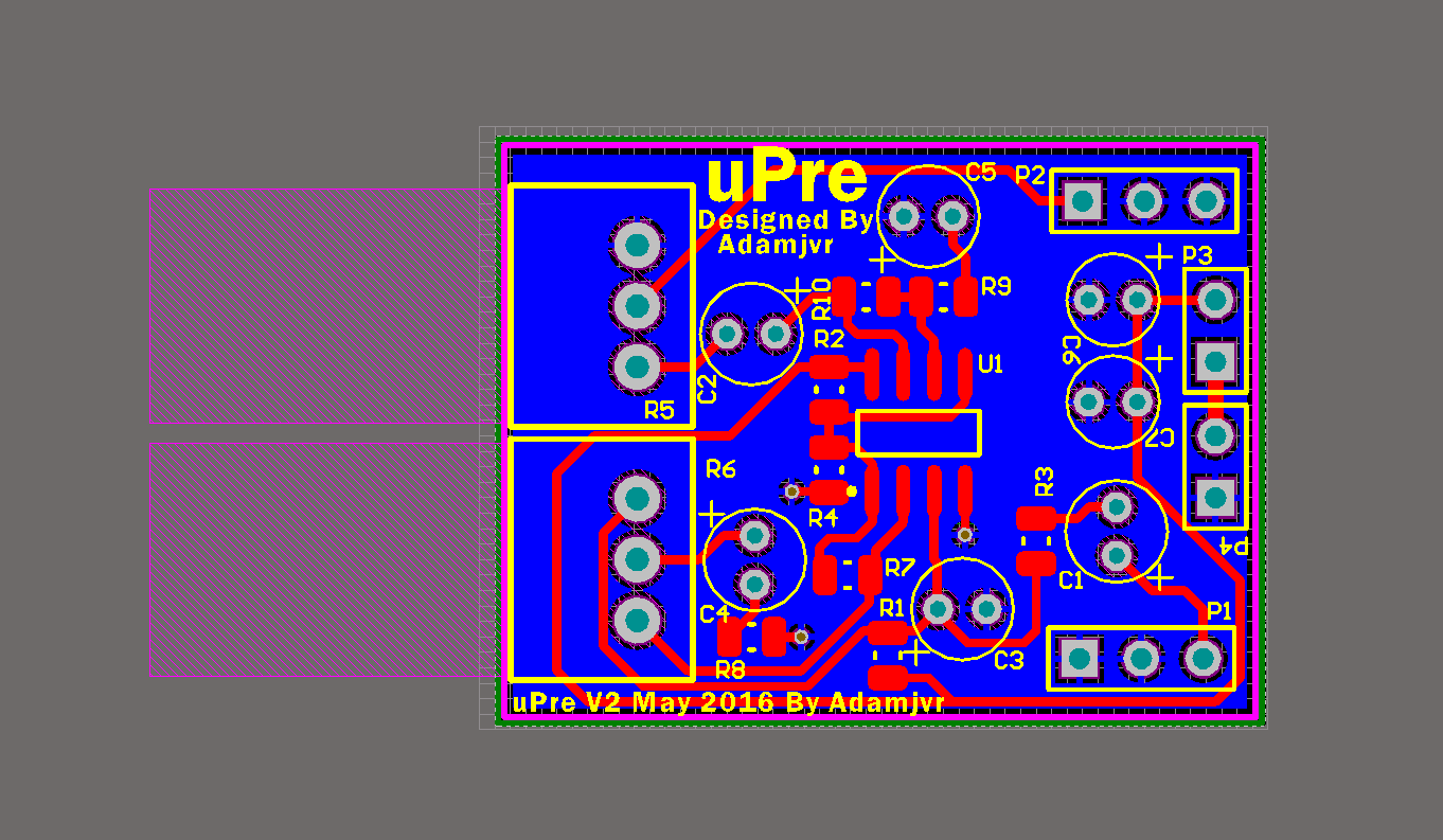
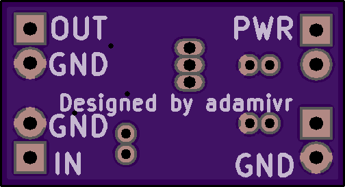
uPre - Electric/Acoustic Instrument Preamp with Tone Control
A simple custom instrument preamp orignally designed for my friend's churango, since redesigned with integrated PCB mounted potentiometers.
https://hackaday.io/project/7704-upre


 Ray Olsen
 DIY GUY Chris
 Bhavesh Kakwani
Analog audio design experiments can include circuit modifications, component substitutions, and testing different topologies. https://www.fortivacreditcard.net/ These experiments can lead to the discovery of new and unique sounds, as well as improvements in performance and reliability of audio equipment.
Best regard,
Langnerfrancesco