 AVR
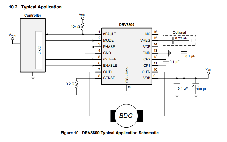
AVRSo for the StepDC I chose the Ti DRV8801 H-bridge chip. It can handle up to 36V at up to 2.8A and it has built in overcurrent protection and monitoring. I chose this chip because it has a wide voltage range and supports a decent amount of current. While the driver can handle up to 36V I designed the circuit to be safe for 24V since components ruggedized for 36V would increase the cost a bit.
Anyways here is the reference schematic from the datasheet:
I'll be using these components:
https://www.digikey.com/product-detail/en/texas-instruments/DRV8801RTYR/296-23638-1-ND/1919072
https://www.digikey.com/product-detail/en/tdk-corporation/CGA5L2C0G1H104J160AA/445-6984-1-ND/2673002
Next off is doing some component footprint creation and laying out the schematic!!
Discussions
Become a Hackaday.io Member
Create an account to leave a comment. Already have an account? Log In.