 Ted Yapo
As Seen on Hackaday
I was honored to see this project on Hackaday this past week! Thanks goes out to @Benchoff and all the fine people there for the attention and kind words.
One of the more interesting things to come out of the ensuing discussion was the "discovery" that tunnel diodes had been formed into a complete logic family in the early 1960s. I took some time to go over the patent (something I normally never do; treble damages suck), and it's pretty interesting stuff. It certainly puts to rest any debate over whether complete logic has been done with diodes before (I changed the project description to reflect this).
I was aware (from Wikipedia) that tunnel diodes had been researched for diode logic applications, but hadn't seen that they formed a complete logic family. Tunnel diodes (aka Esaki diodes) show a negative resistance region (like some other diodes used as microwave oscillators). This negative resistance region makes them useful as amplifiers, and especially bistable elements. The patent cited above uses tunnel diodes that get switched into latched states by input pulses, forming the logic gate. They also require a reset pulse before they can compute again - it's kind of like a built-in latch on the gate output. Antique tunnel diodes are available on ebay - I ordered a few to play with here, but they're expensive and pretty exotic. The kind of diode you aren't surprised you can build computers from :-)
In other news, I've created a new project for anyone interested in experimenting with "active" diode circuits. Check out #Diodes Only.
Control Panel
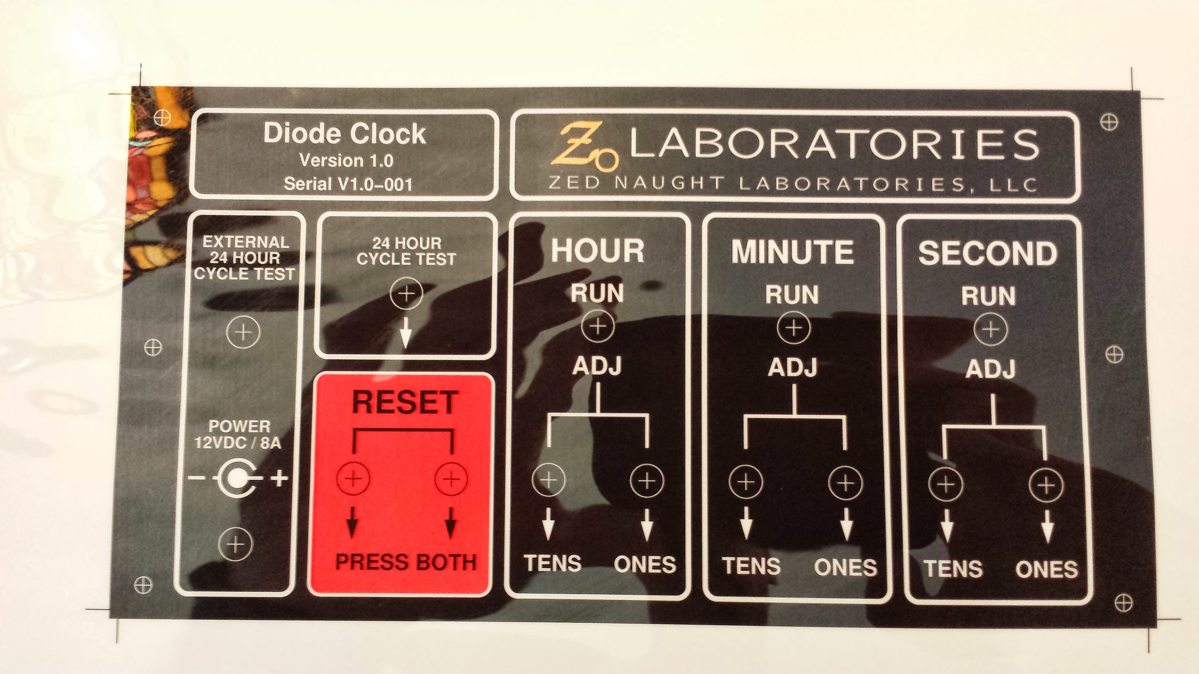
Here's the control panel for the clock:

I think it came out nice (except for the messy threadlock compound that smeared on the panel), but actually represents the biggest blunder I made with the design. See if you can figure out why from the schematic:
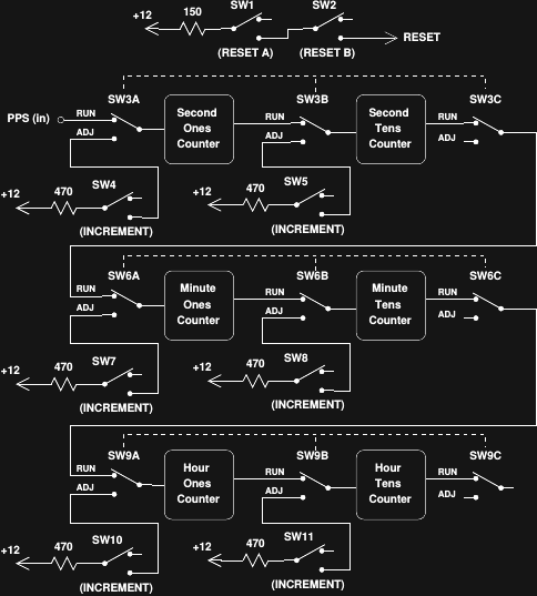
(here's a PDF version). The idea is to be able to isolate each digit counter with triple-throw switches on the input and output pulses, then increment a selected digit with a momentary toggle. With logic this slow, there's no need for switch debouncing, right? Turns out this was a bad assumption. During testing, things seemed to work OK, but as it was all put together, an "audience detector" somehow got incorporated. The clock becomes impossible to set if anyone is watching me do it - the switches start to bounce, and getting a digit set correctly can be frustrating. I always manage to get it to work after a few minutes fiddling, but it really bothers me.
As a result, I'm designing a new panel, using thumbwheel switches, like these:
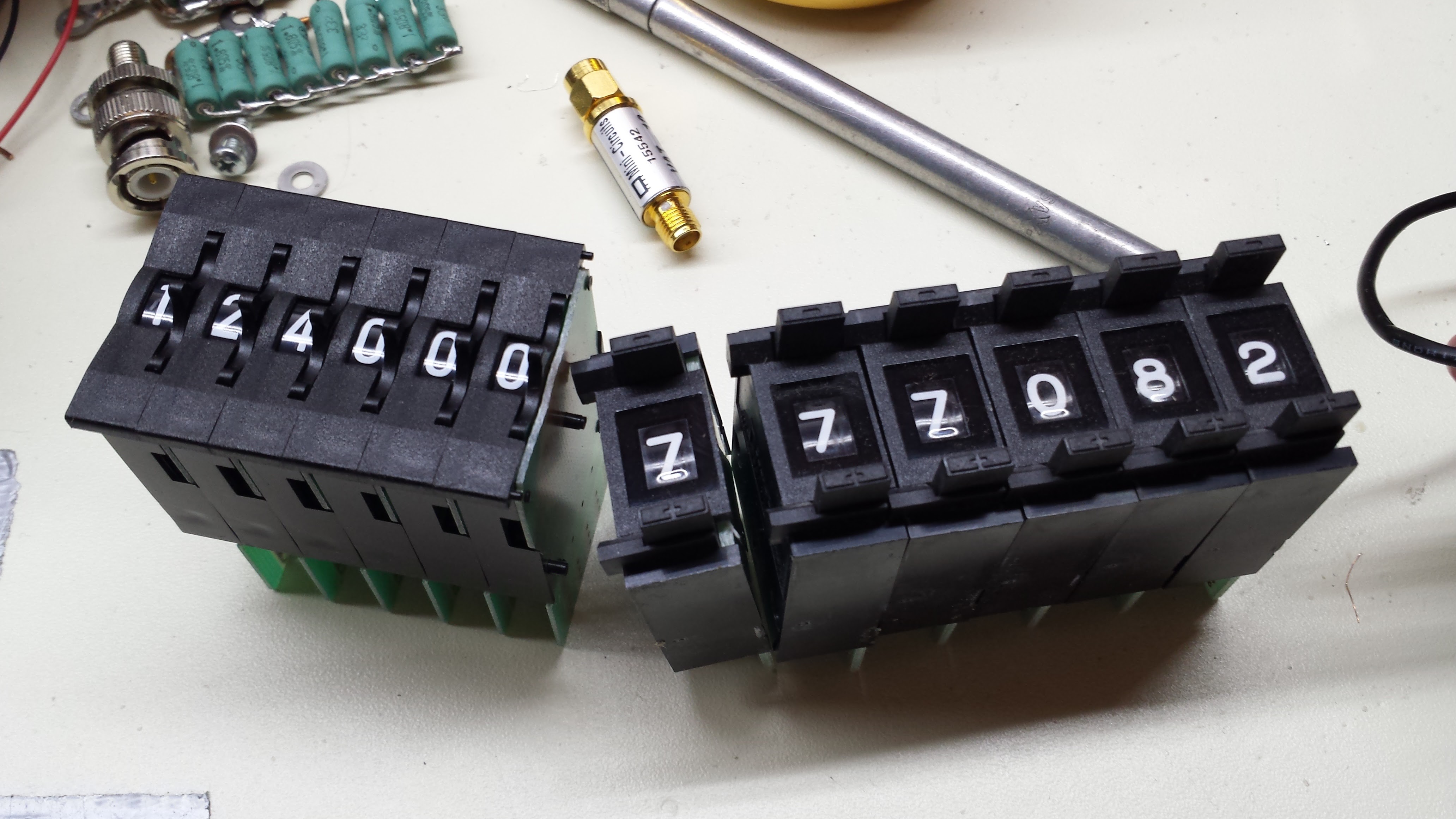
I love thumbwheels. They have a wonderful retro charm like Nixie tubes. The idea for the panel is simple - you dial the desired HH:MM:SS into the switches, then press a "set" button. The clock resets to midnight, then races forward at 3kHz seconds until it hits your appointed time. I'm considering two implementations. In the simplest, the PIC microprocessor in the timebase reads the switches and generates the reset signal and the correct number of 3kHz clocks to set the time. The advantage with this method is that the PIC can compensate for the elapsed time required to advance to the desired setting. If you're setting it to 12 noon, it's actually 12:00:14 by the time you get there, so you want to go past the set time a little to compensate. This is easy to implement on a micro. The second option is to do it all with diodes, where such automatic compensation would probably be impossible withoud adding more gates to the clock. Of course, you could require the user to pre-compensate the time before setting, which would make it a bit of a puzzle to set. I haven't decided which way to go yet.
Making Nice Panels
I use a process for panel labels that I learned from the website of Neil Heckt, who was the owner of Almost All Digital Electronics. In preparing this update, I was sad to learn that Neil passed away in 2015. I've used one of his L/C Meter IIB units for many years, and throughout the development of this clock. His idea was to laser-print labels on the back of transparency sheets and glue them to panels. It works really well.
Here's what I did. I designed the blacked-out label (in xfig), then mirrored it for printing on the back of the sheet. I used a color laser printer so I could also get the red for the reset box. To get the metallic gold logo, I left the area clear, then spray-painted it from the back with metallic paint (the photo doesn't do it justice). I then spray painted the whole back of the panel with white to form the lines and text. Once it was dry, I flipped it and sprayed a light coat of matte finish to take down the shine on the front (glaring in the photo below). I attached the label to the pre-punched aluminum panel with spray adhesive, then cut out the holes with an X-ACTO blade.
One mistake I made was not using panel washers under the nuts. This caused the nuts to grab the transparency and warp it a little. To avoid having to torque the nuts so much, I applied some thread locker to keep them tight, but this got on the panel in places and marred the finish. In retrospect, I think a two-panel arrangement where the switches are mounted to a rear aluminum panel with a labeled faceplate applied after the nuts would have been better.
Discussions
Become a Hackaday.io Member
Create an account to leave a comment. Already have an account? Log In.