Close
0%
0%

Electromagnetic Teaching Aid

A set of designs to facilitate teaching and intuitive understanding of the relationship between electricity and magnetism

Similar projects worth following
Teaching how electromagnetism works is often based around theory and is hard to make hands on, even while it lends itself to very interesting experiments since motion is often involved. This project aims to create a set of designs that can help make the relationship between electricity and magnetism more intuitively understood. By starting with common components I would like to show that by simply arranging them in different ways and controlling the current through the coils you can create many different simplified devices used in everyday life and gain a more intuitive understanding of how they operate and get excited to explore more deeply.

Ideally this would be something that anyone could build without buying extremely custom parts or needing fancy machines.

Devices:
- DC motor
- BLDC
- Stepper motor (unipolar)
- Speaker
- Solenoid
- Relay
- Transformer
- Microphone
- Meter
- Generator

The main part of this project is a design for an easy to build electromagnet that can be easily positioned to interact with magnets or other coils to allow for interactive learning and understanding of the relationship between electricity and magnetism.

Supplemental to this is to provide reference designs for building different devices such as motors, solenoids or speakers.

Additionally this project aims to provide Arduino code and an accompanying chrome extension to provide interaction with the devices in the reference designs.

All of the code and designs are on GitHub and fully open source, I would love to see the collection of devices with support grow.

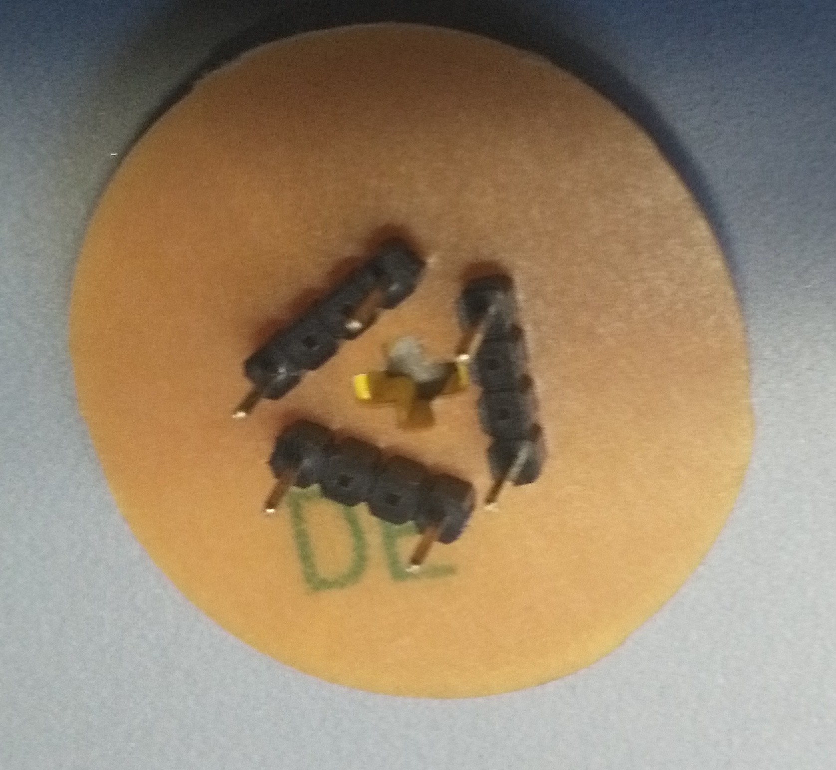
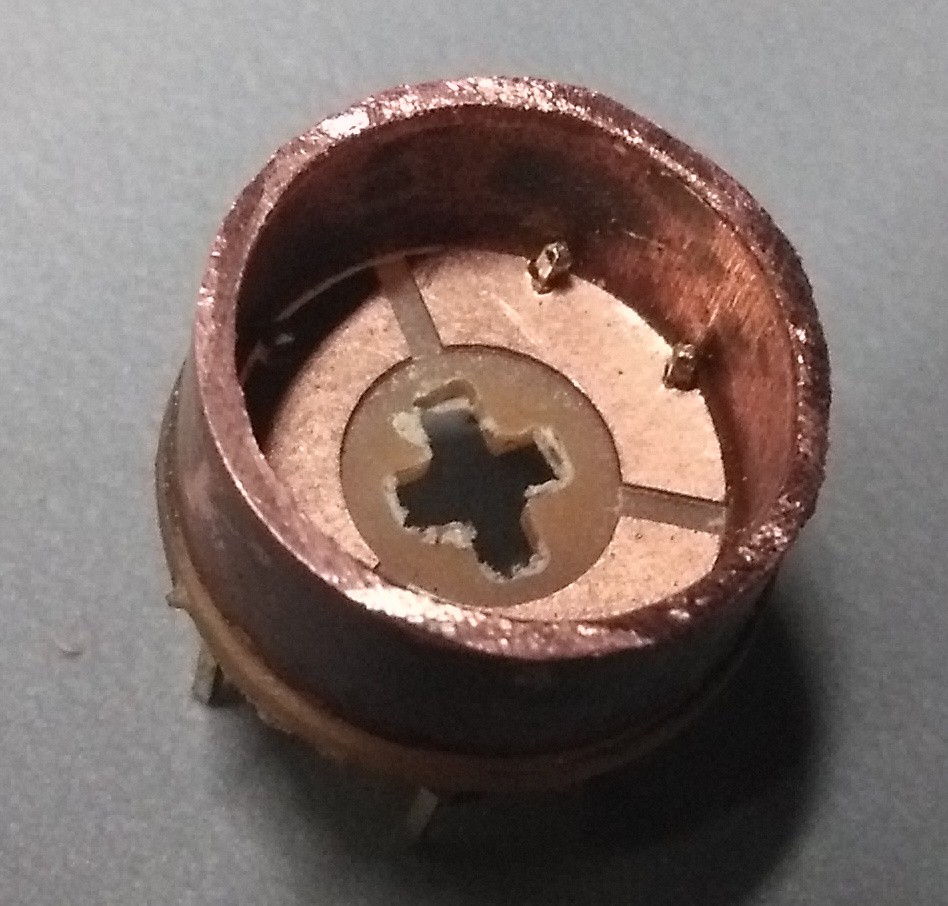
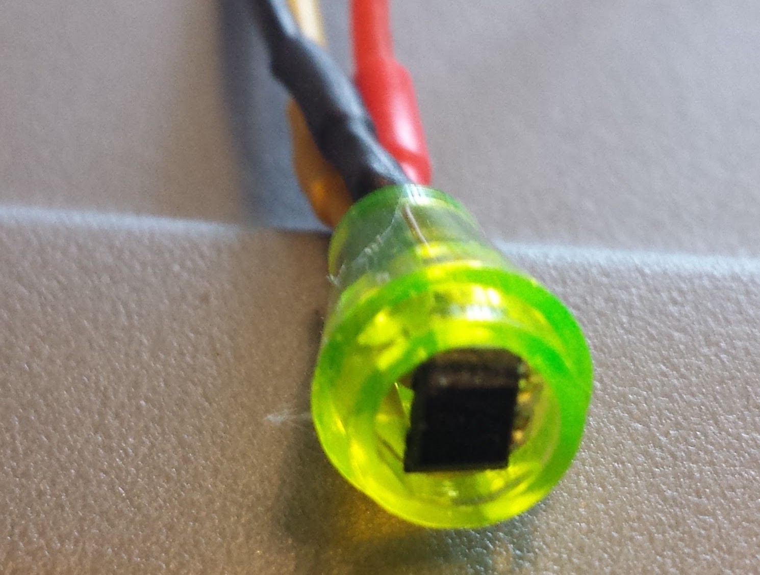
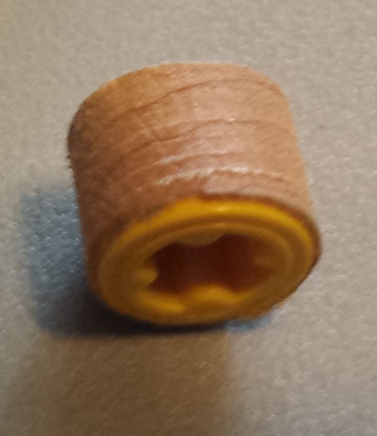
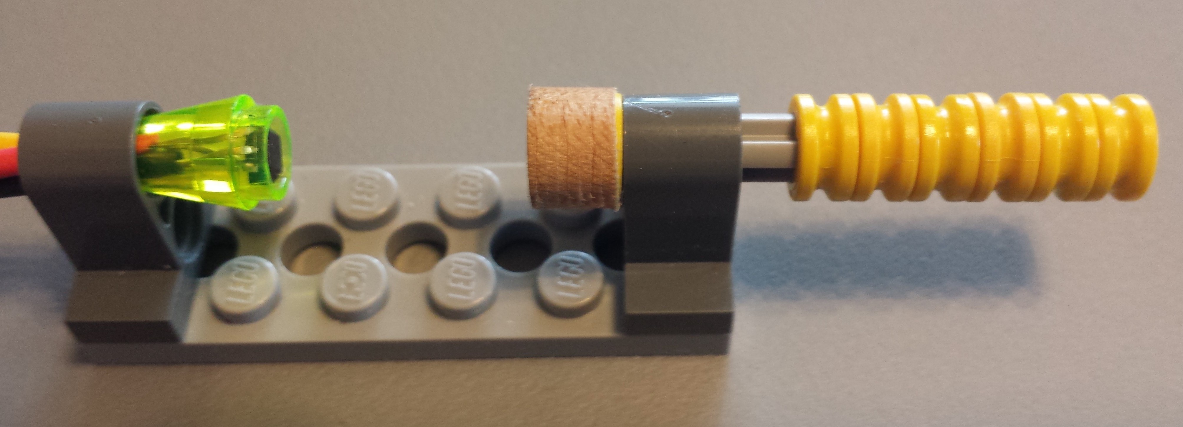
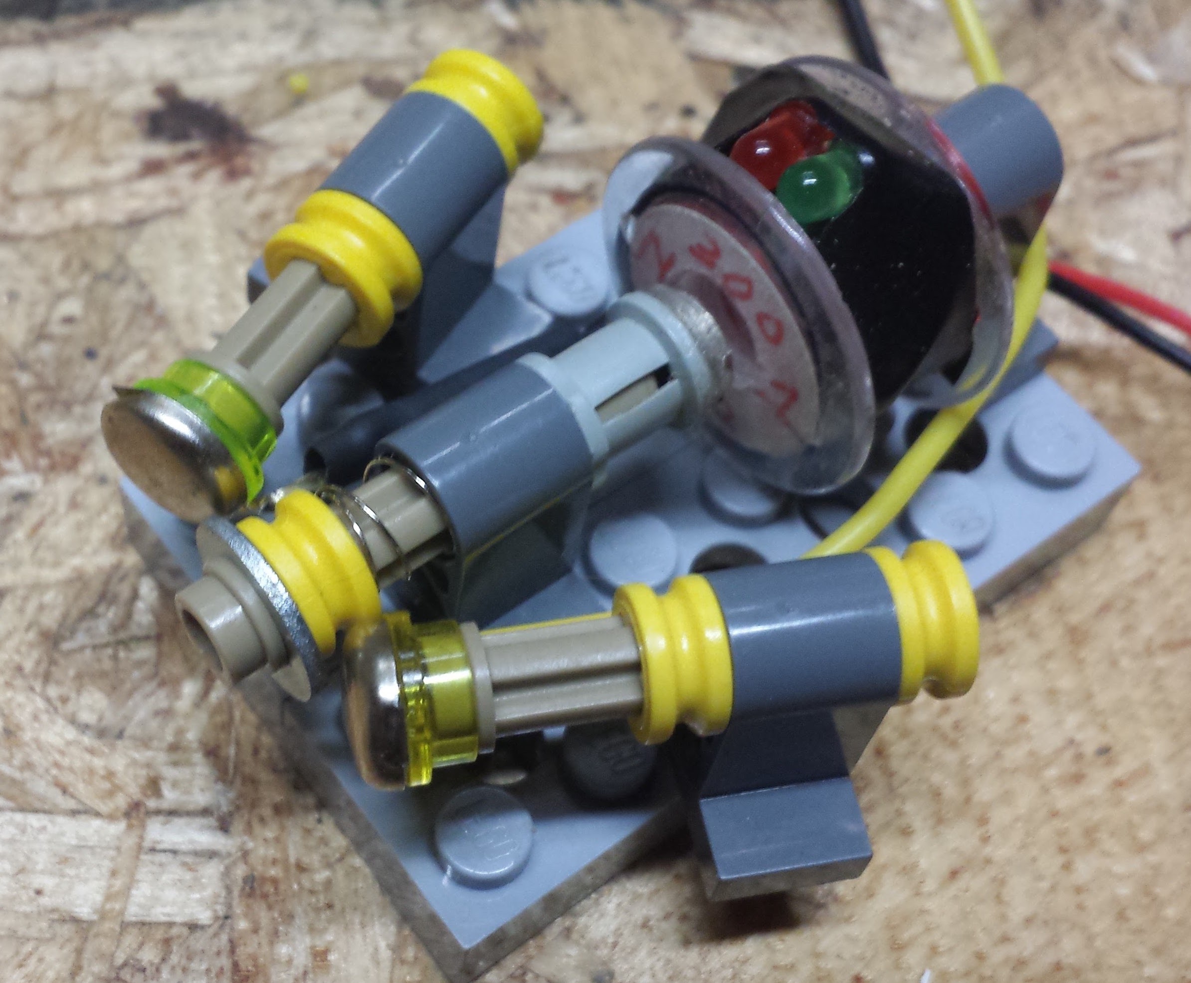
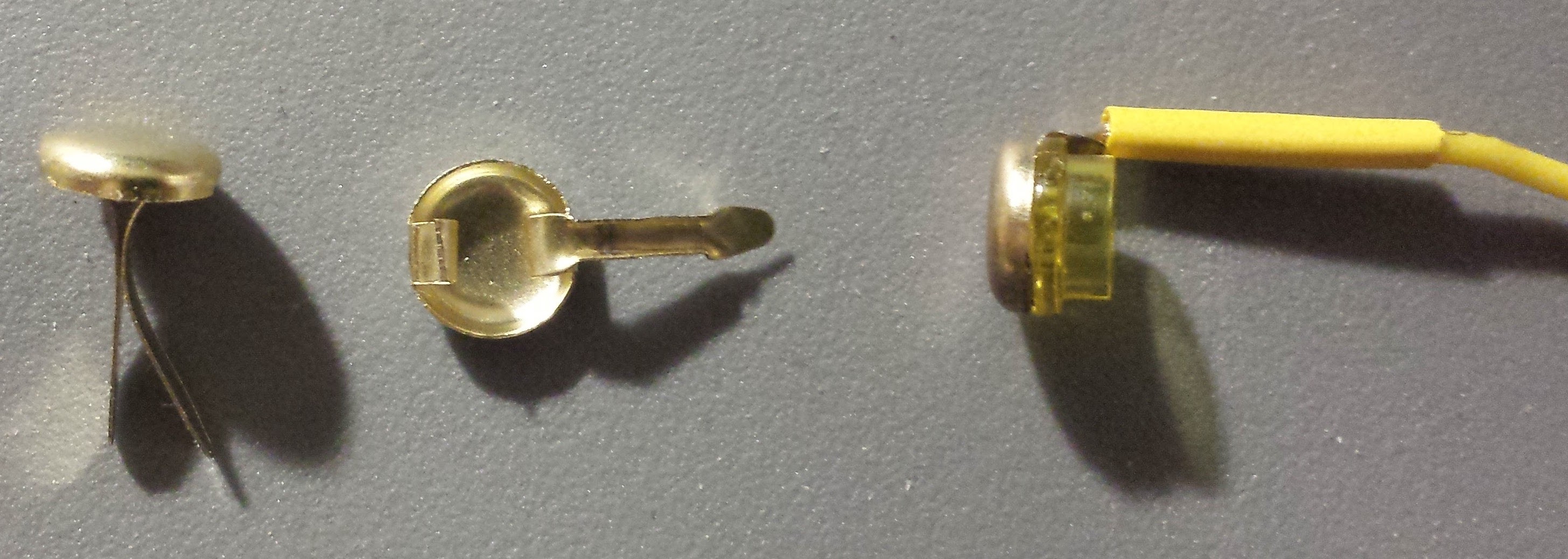
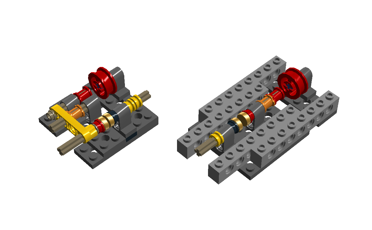
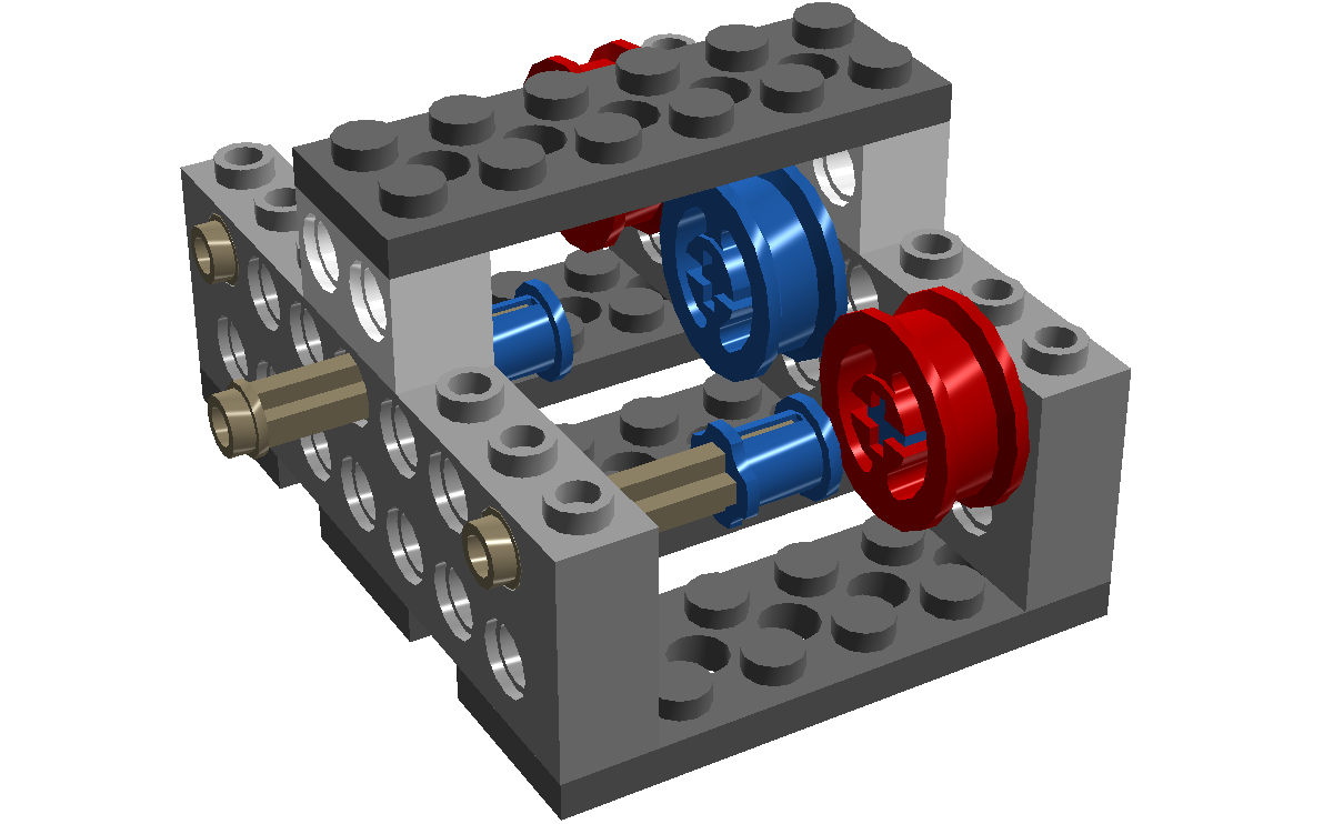
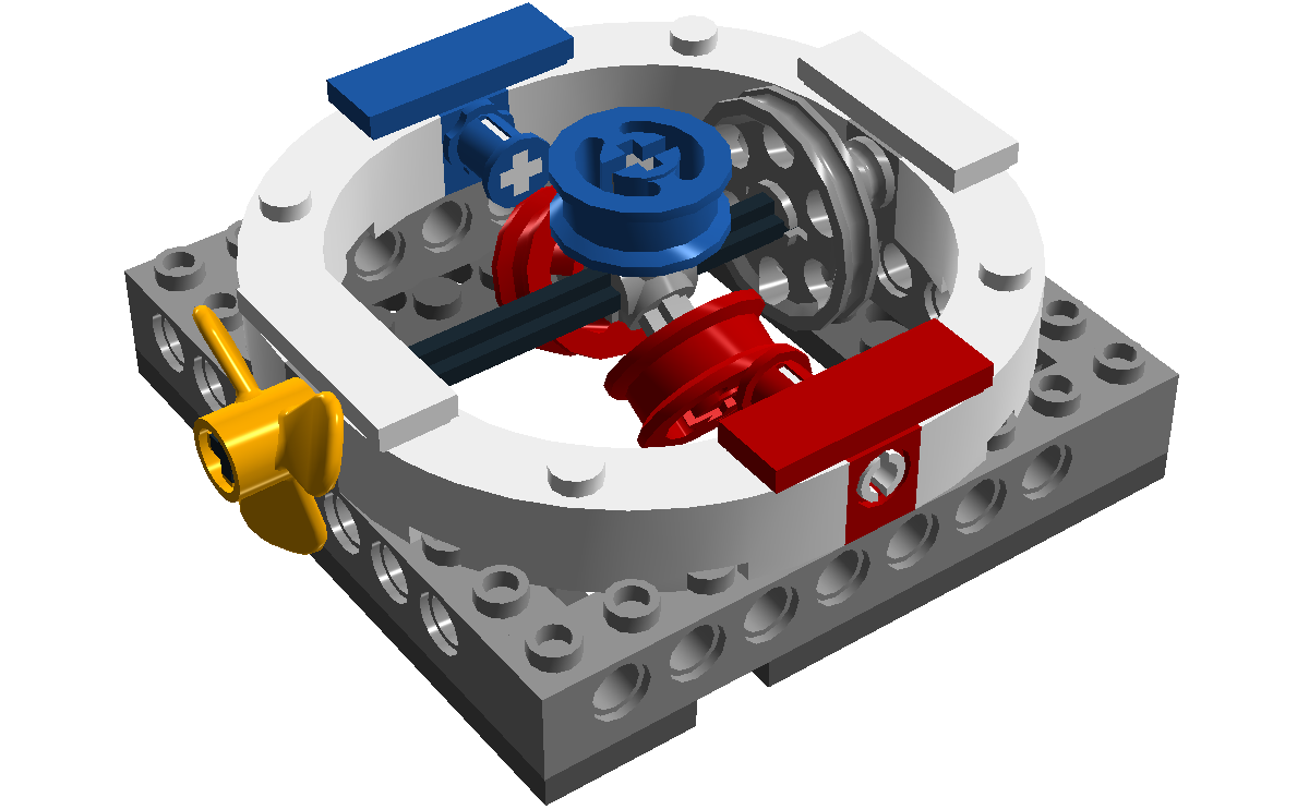
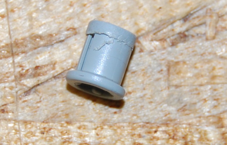
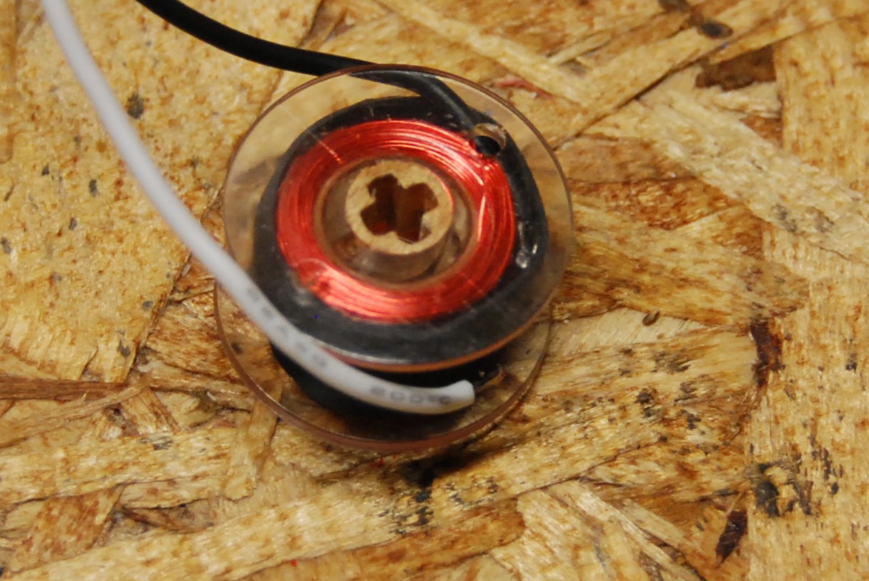
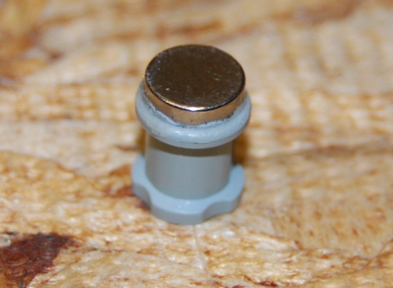
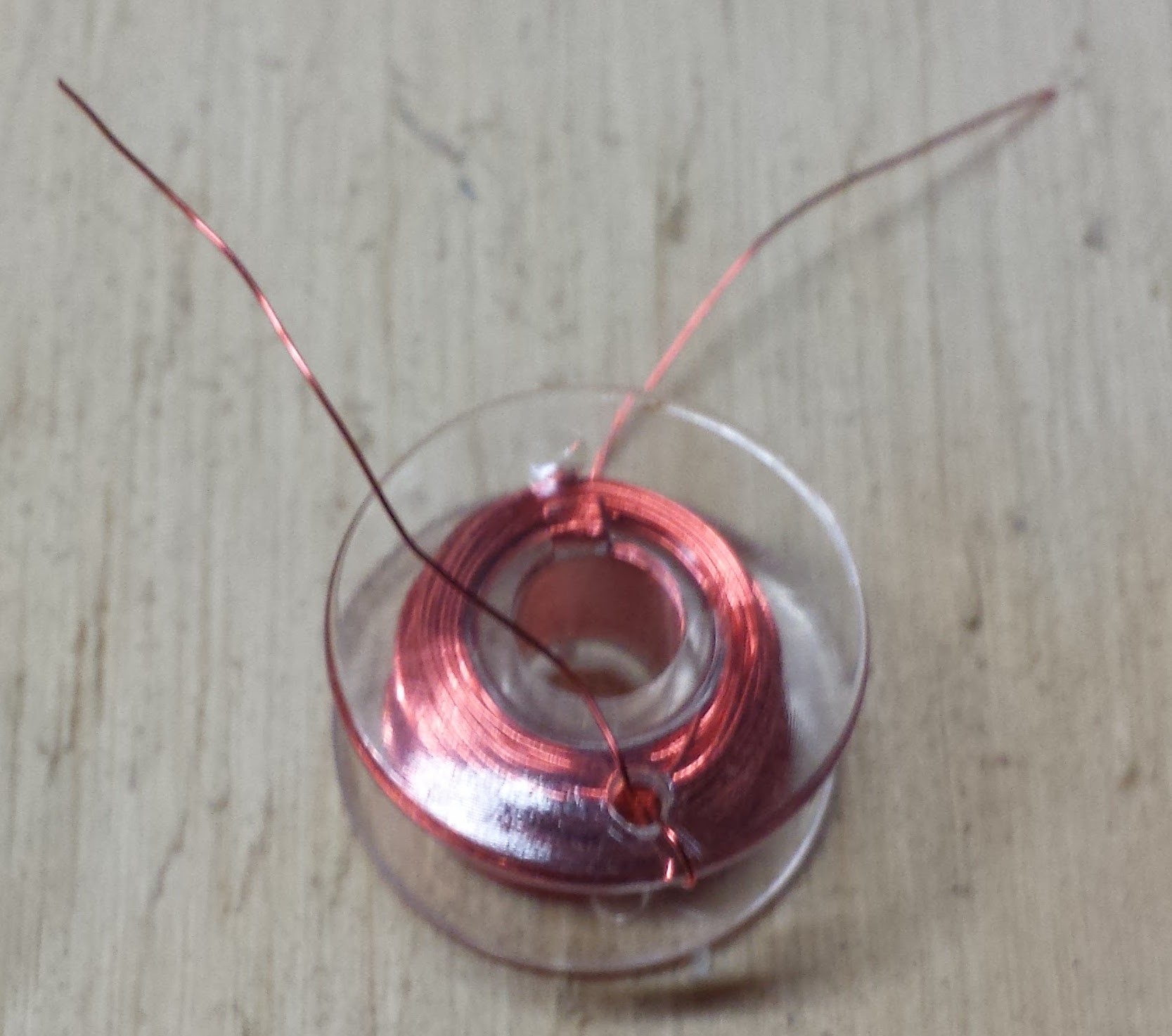
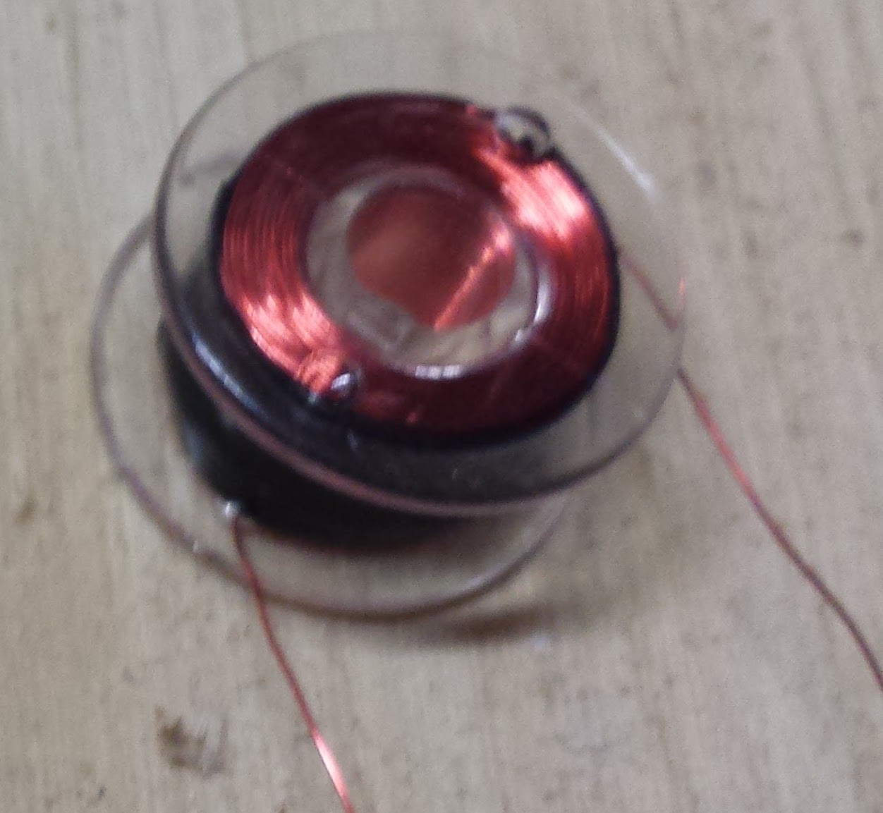
For the coils there are two types to help with wiring up some of the more complicated ones as well as to learn the roll that the direction the coils are wrapped play. I am calling these normally north and normally south, basically if you connect the black wire to ground the front of the coil with the sticker on it will have that polarity. The north type has a red wire as the other wire and a red bush in the center, the south coil ideally has a blue wire and a blue bush but for me currently I have had to use a white wire and gray bush. Additionally for both types the red LED indicates the front side is energized as north and the back as south, and the other LED again ideally a blue one but for me has been green would indicate a south pole. The magnets likewise are mounted such that on a red bushing the magnet facing out is north and on the other color is facing south.

`

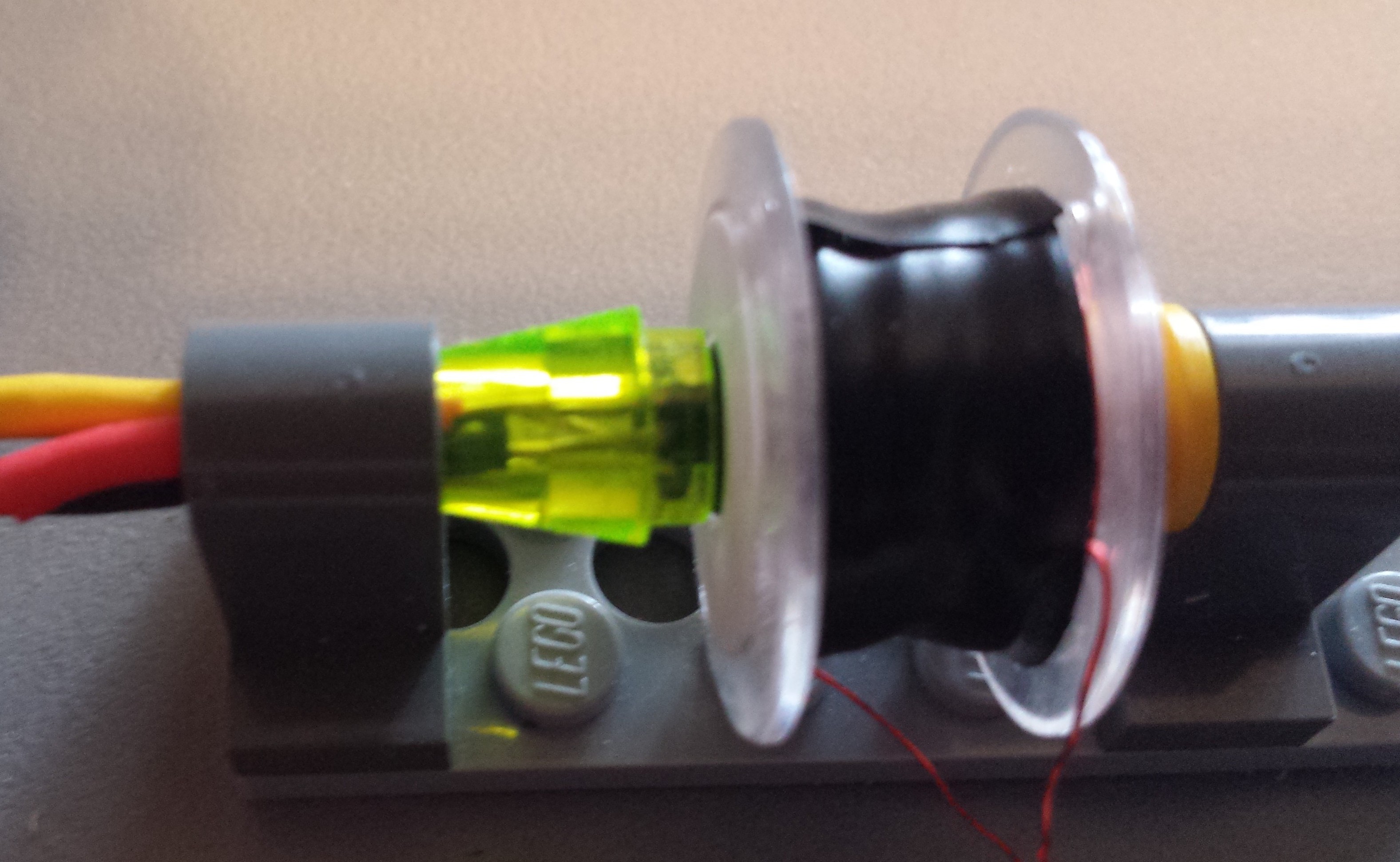
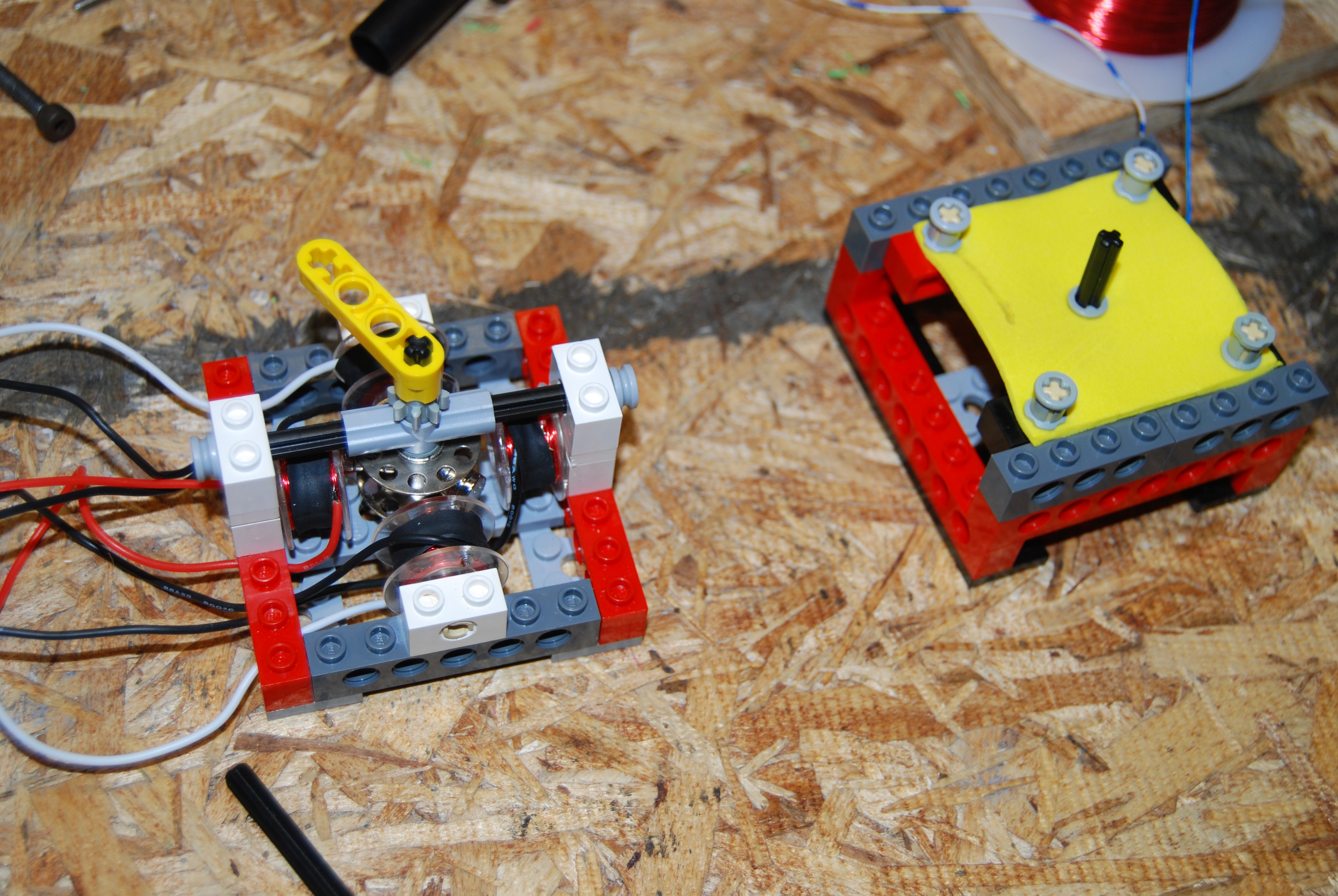
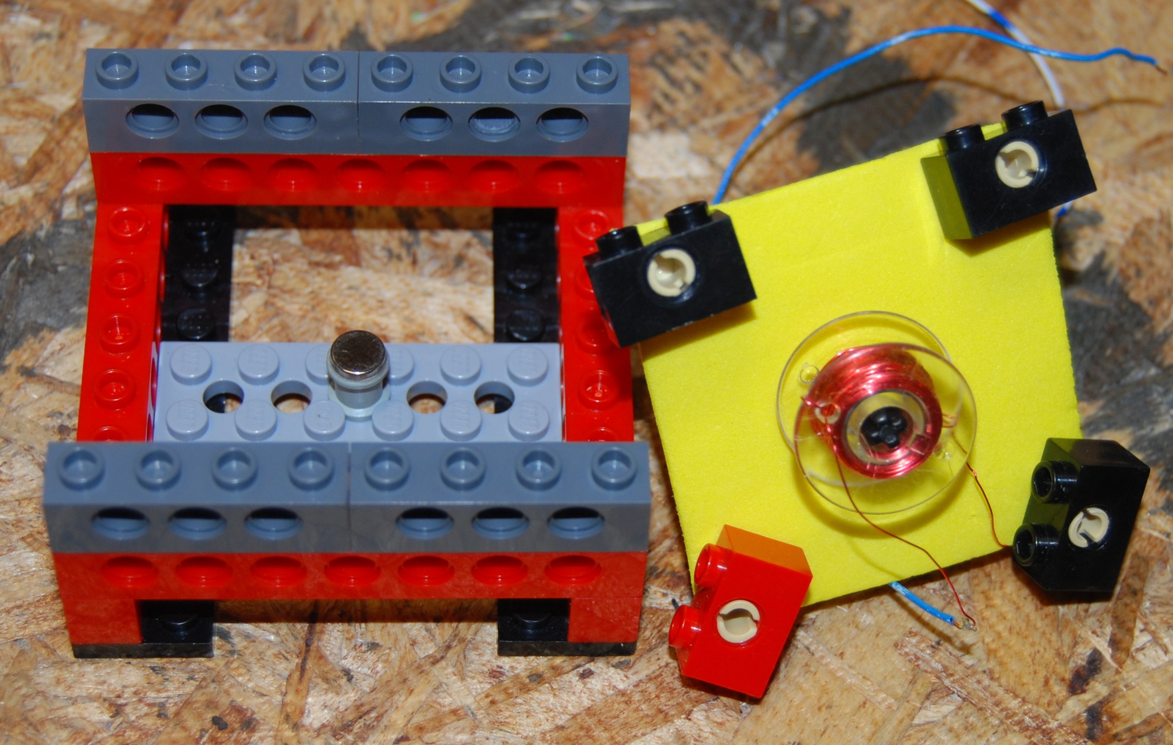
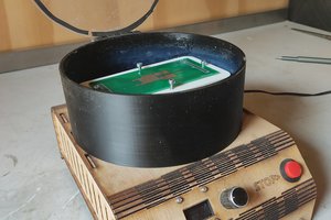
So as you can see here a normally north magnet powered with 5v on the red wire and ground on the black lights with a red indicator and pulls the south facing bushing toward it.

and the opposite can be seen here

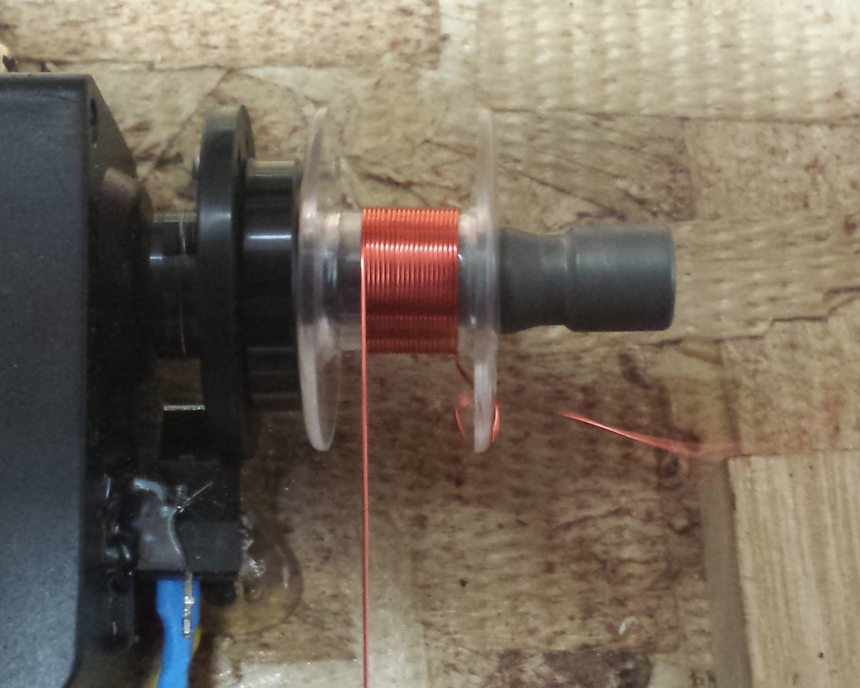
You can see the build instructions for more details on how to make them.

The end goal with this is to have a kit with 2 of each kinds of coil, 3 of one kind of magnet and then one of the other type, along with a collection of Lego that allows you to build the reference designs as well as encourage free play.

BOM.pdf

List of lego part numbers and quantities

Adobe Portable Document Format - 24.34 kB - 05/27/2016 at 03:05

Preview
Download

  • 4 × Sewing Bobbins Standard plastic sewing bobbin
  • 1 × 30 Gauge wire
  • 4 × Neodymium Magnets 1/4" by 1/16"
  • 1 × Various Lego see included file BOM for current list most important are the technic bushes
  • 1 × Arduino

View all 14 components

  • Progress is fun again!

    Adam Smallcomb10/02/2016 at 22:40 0 comments

    I struggled with designing a speaker not because it was difficult to make it work but because I kept expecting it to be harder and over-engineered the design over and over again, in the end the design for this one is rather simple and with a few modifications (shape of the magnet holder) could probably be even simpler. Here is this module as it stands today in action:

    Currently the best way to drive the speaker is with the kits h-bridge, by opening the chrome extension included in the project go to the speaker section, there you can will find a few short songs built into the Arduino code to play. Additionally, using the home row of the keyboard you can play an octave of notes. All of these notes are just square waves so using some more intelligent code I should be able to produce a more pleasant sound using the h-bridge as more of a DAC . I have also hooked it up to the output of a stereo and the result is surprisingly good (not great mind you) but in trying to keep the project self contained I wanted a way to use the speaker without needing to find a stereo. Furthermore I would like to make it possible to use the h-bridge as a class D amplifier inspired by this project http://hackaday.com/2014/12/28/class-d-amp-with-an-h-bridge/, it seems like that should be possible with more time on the software side, even if the quality isn't spectacular it should be good enough for this, I mean its a Lego speaker!

    Additionally now that its possible to add screws to the coils I have been working on redesigning the relay to not require a spring in order to reduce the number of unique components needed and the initial results are promising with better reliability and less finicky component placement, but I am trying to have a more finalized design before I post that again.

  • Procrastination!

    Adam Smallcomb09/15/2016 at 19:07 0 comments

    It's been a few weeks since the last update, partially because life happens and partially because I was procrastinating...I was somewhat nervous that the brushed dc motor wouldn't be strong enough. This week I started back up, unfortunately in my original design that seems to be true. Thats what development is all about, it wouldn't be fun if everything worked the first time, right?. So this post is going to be an update on the failures at this stage and I am going to develop out some of the other aspects of the project first and continue to optimize the coils and improve the other components, as well as continue to think of some improvements to the brushes and so forth until the dc motor portion works. On the plus side after building it out I realized that with the LEDs on the coils you should be able to see as it spins what phase the coils are in during the different parts of their rotation as they strobe the different colors.

    Here is the full assembly,

    The commutator looks like this -

    I liked the design because it provided an easy way to build it (made my first prototype just using a hole saw and blade) as well as a straight forward way to make a bunch of them. Additionally I felt it made it easy to observe how it worked. However this method proved to have way too much friction especially since the motor appears to be way underpowered at this point.

    I began working on a more typical commutator configuration using a copper pipe, but ended up stopping until I can get the other parts more optimized. The intention was to solder the pins and the pipe edge to the board and then cut slices in the pipe afterward to line up with the slices on the board.

    To ramp my motivation and inspiration back up I will focus on some other parts, probably a rework of the coils (primarily higher turn count) and a working speaker demo now that I have the parts for that.

    If anyone has any ideas for improving this one (or any part really), please let me know!

  • What the flux?

    Adam Smallcomb07/07/2016 at 18:21 0 comments

    I finally got around to taking some qualitative measurements to go along with the Hall-Effect sensor so I figured it was a good time to post another update. Here is the new component being added to the kit, it is a A1324 hall-effect sensor with an output voltage that is proportional to the magnetic flux density. This sensor is then mounted in a nose cone small 1x1 lego with three wires attached and female Dupont connectors at the other end of the wires.

    The reading from this sensor is now also displayed in the chrome extension included in the github repo.

    After much use I another magnet came of from the original design as well so I am now experimenting with a few configurations, the most promising I used for the following experiments and basically is a thin shell over the magnet and a half bush.

    Using the sensor I took measurements of this new magnet at a range of distances as measured by inserting half bushes to the axel.

    For this next graph I created a range of coils with 100, 200, 300, 400 and 500 turns of wire. Because the coil is confined to a short shaft as the number of turns goes up the length of wire goes up disproportionately more per turn, causing greater resistance per turn on the the higher counts than the lower ones. We can use this to our advantage though to some extent, we can ideally find a count that reduces the current needed to something manageable by the h-bridge, less than 1.5 amps and ideally closer to 1A for continuous. You can see in this graph why I have been using around 300 as this seems to be the peak efficiency I had found iteratively, though seeing it quantitatively is nice. After testing with some set screws in there I am beginning to consider closer to 400 may be ideal as it gives a much bigger boost with a screw and will use less current. There are 4 distinct data sets represented here, each coil was measured with 5v and 12v and then again with the set screw in the center with both 5v and 12v again. This was done by using a 1/4"-28 tap and then using 1/4" long set screws on the front side of the coil they screw in until just under flush.

    For the final kit I would like to design some experiments where we use the h-bridge to set the multiple different voltages.

    The Experiment was set up as seen in this image

    Because I was limiting the current some of the lower end counts were at a disadvantage but even short bursts at the full current that would be pulled would have melted the plastic at the very least. Even with that though I think some interesting conclusions can be drawn.

    The next update will be of the dc motor, with what I think will be the final new component: the commutator!

  • Long lost update

    Adam Smallcomb06/22/2016 at 19:16 0 comments

    In my last update I promised a video of a relay working so here it is

    The relay used looks a little different then the ones I showed in the last update because I was having difficulty with reproducing it without fussing every time to get everything just right and moving one of the contacts that had a wire attached was influencing the system too much. Instead I put a washer on one of the shafts and moved that, this seems to me much more predictable however I still expect to keep iterating on this design so that the directions won't have to include "move until it almost touches". Also I am still experimenting with spring replacements

    Here is what the piston looks like

    and when its all together the version in the video looks like this

    Also last update I was having trouble with magnets sticking well and indeed scuffing them up before glueing has worked much better as you would expect.

    Up next will be the inclusion of a hall effect sensor component and then I believe the last component will be the commutator for the brushed DC motor, with several additional reference designs following that. So look for those updates soon!

  • Slow and Steady

    Adam Smallcomb06/09/2016 at 16:19 0 comments

    Progress over the last week or so has been a little slower. Both from just being busy but also from a few setbacks, lets catch up. The next device I tackled was the relay, this required a method to make electrical contacts that could be moved by energizing the coils. I figured whatever I made these out of should also be able to be used as the brushes on the brushed dc motor design. Because I want these items to be something that can be produced with a high quality without specialty tools I began by targeting something off the shelf that I could modify. My first though was to use brass tacks thou I was unsure how to attach a wire and mount it to some kind of lego piece an still make it look consistently clean. My wife suggested brass brads, and these have worked excellently so far. I started by cutting one of the legs off of the brad and starting a crimp on the other. Next I placed a wire in the crimped section and completed the crimp, then covering the area with shrink wrap you end up with a solid clean connection without even soldering (the wrap in the picture hasn't been shrunk yet). Lastly a round 1x1 Lego plate can be pressed in and so far has stayed for me without any glue though I am sure once finalized I will be using something to make it more permanent.

    This brings me to one of the setbacks and the reason I don't have a video of the relay working, it turns out that just using super glue (cyanoacrylate) on the magnets does not give a sufficient hold. After handling the magnets a lot more for this build all of the magnets I had previously glued on came off, this is obviously not acceptable. It has been recommended to scuff the surface first and that may help, I will certainly try it. I am also going to try using epoxy I think and trying to cover the magnet completely to really grab it.

    I made both versions shown here and both have there advantages. The one on the left connects when the coil pulls the magnet and the one on the right when it pushes away. I used a return spring (orange) for both versions and while that worked the spring was really more stiff than I would like and I am currently experimenting with other "spring" materials. The one on the left is more compact and because it gets closer as it pulls does a better job compressing the spring and thus has a better return action. The one on the right I feel is less complicated to see function and is certainly simpler to assemble.

    Once I have the magnets figured out or at least some new ones to test I will get a video of the relay turning on a light.

  • Let's See it in Action!

    Adam Smallcomb05/30/2016 at 19:27 0 comments

    Ok, it's been long enough lets see see this in action! First I have a short video just showing the coils acting as a solenoid and then in a stepper motor configuration being controlled with only buttons to prevent this project from being to complicated or expensive to start.

    and next we have the same stepper motor configuration being controlled from a laptop talking to the Arduino from a chrome extension installed locally available for this project in the GitHub repository. The code is still pretty early on but can give a feeling for where it is heading overall.

    There is code supporting the solenoid and speaker to some extent so far and work is still being done all around on the code. I believe the design for the coils is pretty stable from here out though I am experimenting with a removable ferrous core potentially utilizing a large set screw.

  • Coming together

    Adam Smallcomb05/27/2016 at 03:05 0 comments

    An update is definitely due, and much progress has been made. For starters I thought I would talk a little bit about my overall plans for this coming together. As stated earlier I would like this to be a set with as few parts as possible that can be rearranged to make different devices using coils and magnets. The intention is then to use an Arduino and a cheap h-bridge to drive the coils in whatever way is needed for that device. This will allow for different types of control: fast control when needed (think speaker or stepper motor ) and binary rough control when that is needed (solenoids an relays) as well as intensity control for speed and direction control for something like dc motor. So along with that I am making a chrome extension that talks to the Arduino and controls the h-bridge. I will show this a little once I finally get around to making a video. All of the code is in GitHub already.

    To start I am focusing on the solenoid, speaker and stepper motor with the meter coming in soon after. The dc motor will need some kind of commutator so will need some more custom parts but I am trying to make them reusable for other builds like the relay.

    Now that that is out of the way I would like to show some of the progress on the designs. I have been introduced to the Lego digital designer and that has helped me iterate much faster. In the following images the wheel hubs are placeholders for the coils with two different wireing patterns and the blue and red bushes are the north and south magnets.

    Here is the stepper motor (this design is the one I am currently working with and I quite like)

    Here is the speaker, the orange bush here represents a possible spring

    Here is a concept for the meter but I haven't been able to test it yet

    Here are some solenoids, this one I think I am going to simplify a bit

    and here is a preliminary design for a dc motor where the disc with 6 holes is a placeholder for the commutator

    All of these designs can be built with reusing most of the same parts. I am uploading a part list for buying these parts from Lego directly. I am sure this list will waver some as I finalize the kit over the next few months and am able to get some of the parts I don't already have on had for testing. As it stands though the cost would be under $10 for the Legos.

    Look for more updates over the next few days as I have will be getting the software more nailed down.

  • Progress!

    Adam Smallcomb05/19/2016 at 16:21 0 comments

    Over the last week I have been trying several iterations and attempting to identify the form factor and composition for the common components needed.

    The first design choice I finalized was in how to mount the coil. I first made a prototype with a Technic Bush that I sanded one end of to look like this

    this can then be inserted into the bobbin to allow it to mount easily, i think if i were to do it this way again I would sand the other end. This would work if trying to make your own but since I didn't want to destroy all of my parts I used my CNC mill to make a part out of some maple and press fit it into the coil.

    I struggled with how I wanted the magnets to mount, I considered attaching to a 1x1 circle or making a custom part. In the end I decided on gluing a magnet to a Technic Bush like this and then using a red version for the opposite polarity, this gives multiple mounting options and an easy way to identify polarity.

    By having both parts mount in the same way I believe it will provide and better opportunity to demonstrate how they are two sides of the same thing, as well as providing reuse of more parts.

    Here is a picture of a more finalized (and working) stepper motor which is one of the more complicated to lay out

    I am waiting on a Lego to improve the rotor and make it more stable without making a custom part that will allow me to use the magnets as built so I will have one more update on that with a video once I get that in and set up.

    You can also see an initial prototype for the speaker that works but I think I would like it to look more like a speaker and not require the foam piece if possible.

    Overall some good progress, I would like to post in the next few days a detailed build for the coils.

  • Current State

    Adam Smallcomb05/13/2016 at 18:46 0 comments

    I have already been through several revisions while doing initial prototyping and have found that Lego will be suitable and in fact preferable for creating layouts as it will provide the greatest flexibility with new ideas and not require much in the way of custom parts. So far I have successful proof of concepts for solenoid, speaker and stepper motor and will post some progress photos tonight. The coils can be easily made on sewing bobbins which also provides a great way to mount them. I originally figured steel would be best providing for better heat dissipation and an iron core the could be further improved by mounting with steel screws. This however proved problematic when creating pretty much each device for different reasons. In the end plastic bobbins are cheaper more consistent and interfere less, and while that may not make the most efficient electromagnet we are more concerned with teaching the how not getting the most out of each. It is still possible to mount with screws or pass an iron core through for individual configurations that require.

View all 9 project logs

  • 1
    Step 1

    Take a standard plastic sewing bobbin and drill a hole as close to the edge without breaking through the edge with a 3/16th in bit.

  • 2
    Step 2

    Using 30 AWG wire loop one end through one of the holes that hopefully came in your bobbin, if not use the hole you just made. Wrap 300 turns onto the coil and then loop the other end through the other hole. This will result in a coil with roughly 4 ohms of resistance so I would recommend checking if your are in the right ballpark when you are done.

  • 3
    Step 3

    At this point you should have a coil that looks like this

    Take about 3" of electrical tape and cut it directly down the middle wrap one of them around the coil. Then un-loop the wires from the holes so that they are on the inside of the bobbin above the electrical tape. Clean off the varnish from the tips of the wire and using a flame or scraping it off. Your coil should now look like this

View all 11 instructions

Enjoy this project?

Share

Discussions

Similar Projects

Does this project spark your interest?

Become a member to follow this project and never miss any updates