 Adam Smallcomb
I finally got around to taking some qualitative measurements to go along with the Hall-Effect sensor so I figured it was a good time to post another update. Here is the new component being added to the kit, it is a A1324 hall-effect sensor with an output voltage that is proportional to the magnetic flux density. This sensor is then mounted in a nose cone small 1x1 lego with three wires attached and female Dupont connectors at the other end of the wires.
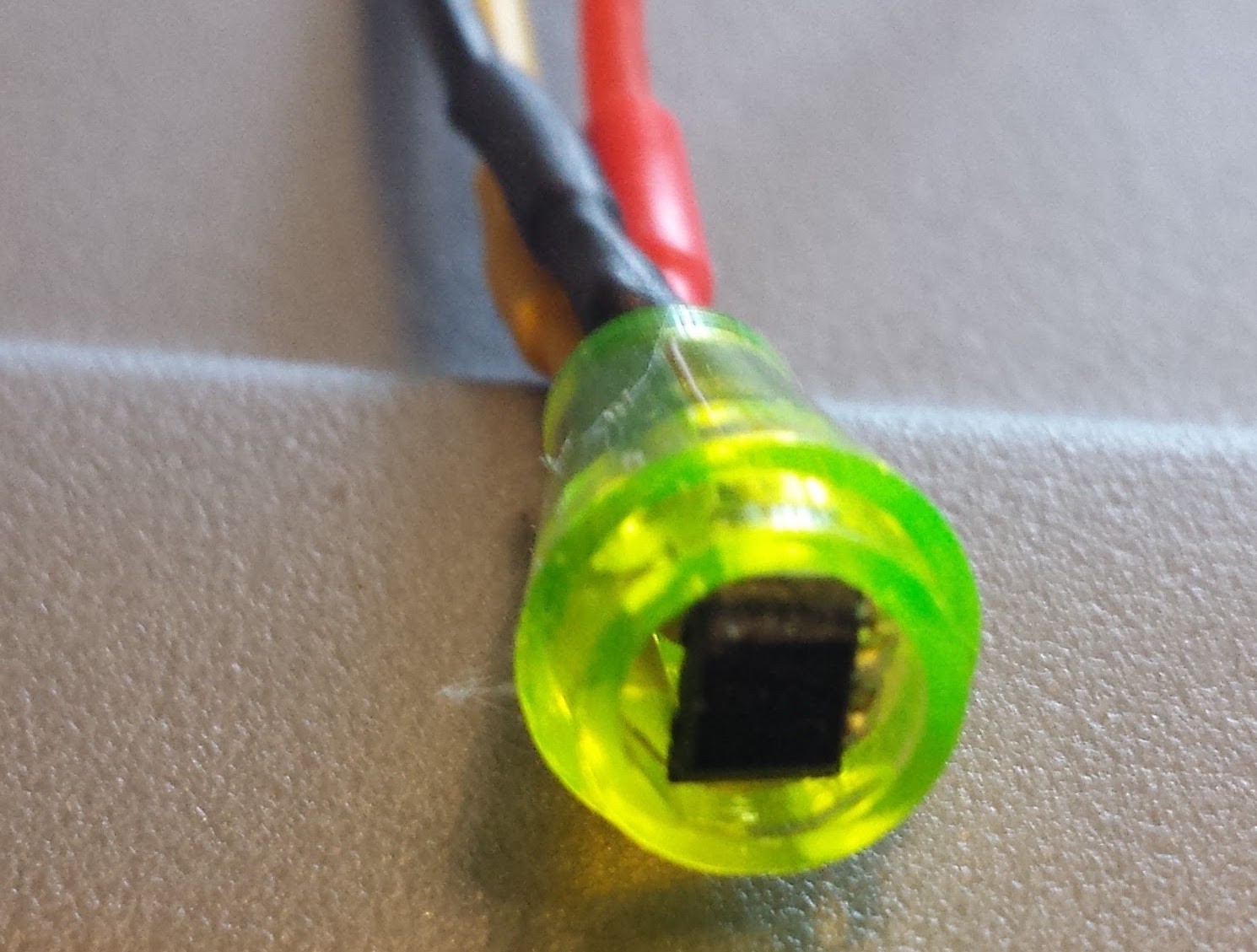
The reading from this sensor is now also displayed in the chrome extension included in the github repo.
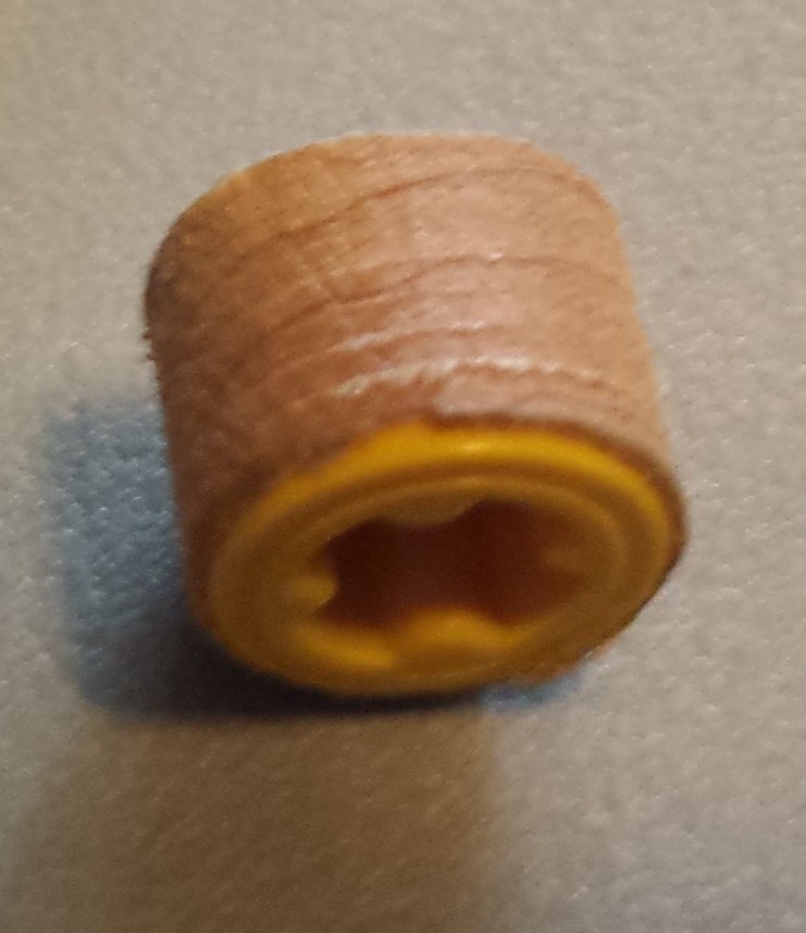
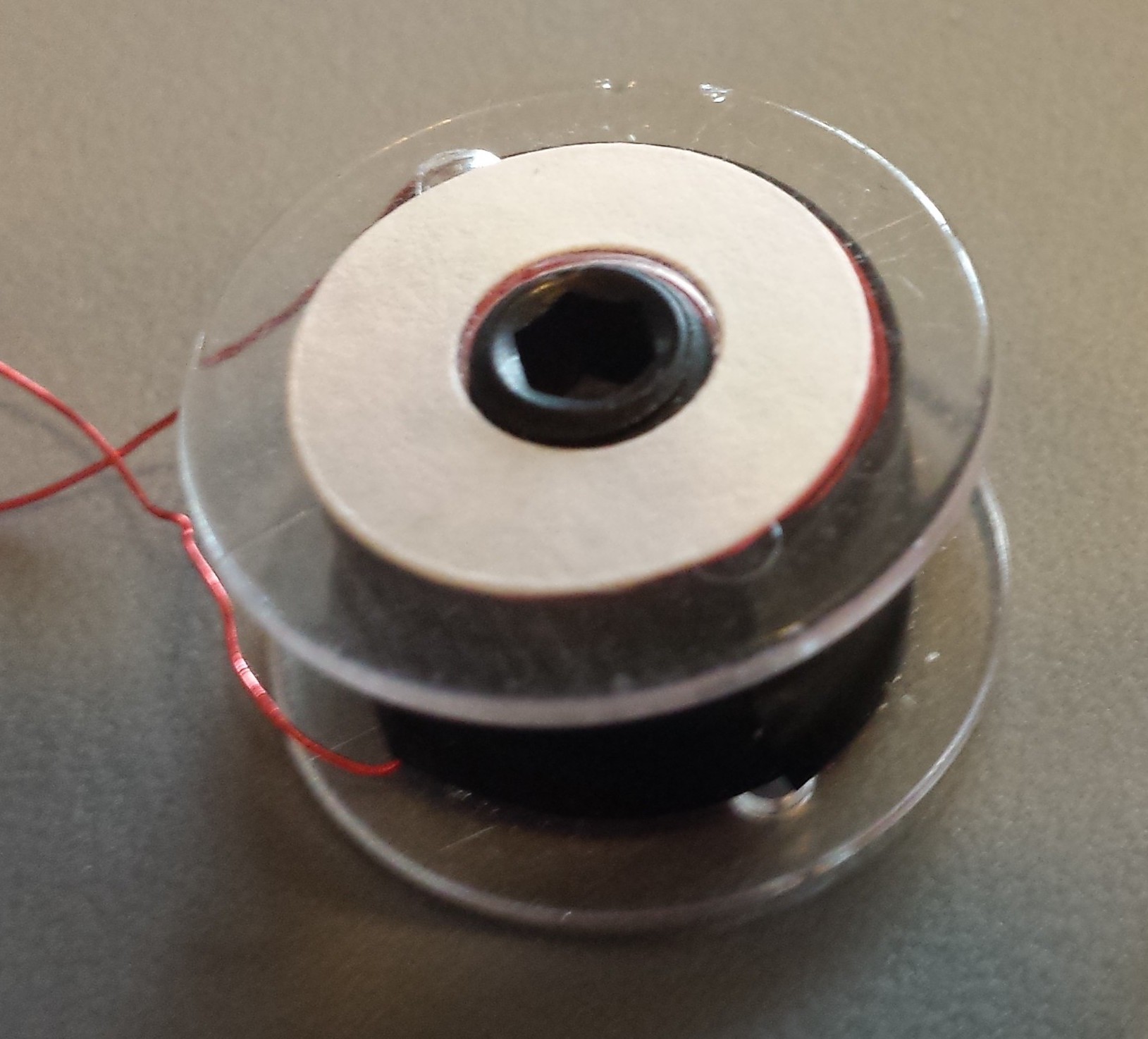
After much use I another magnet came of from the original design as well so I am now experimenting with a few configurations, the most promising I used for the following experiments and basically is a thin shell over the magnet and a half bush.
Using the sensor I took measurements of this new magnet at a range of distances as measured by inserting half bushes to the axel.
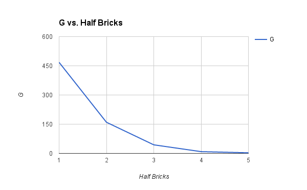
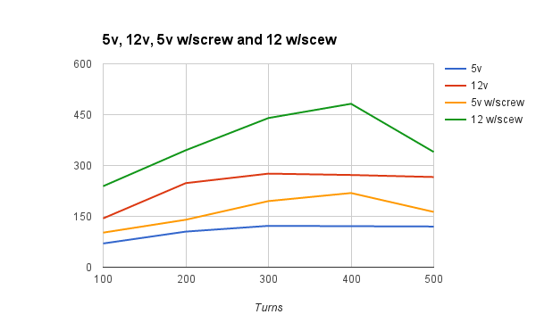
For this next graph I created a range of coils with 100, 200, 300, 400 and 500 turns of wire. Because the coil is confined to a short shaft as the number of turns goes up the length of wire goes up disproportionately more per turn, causing greater resistance per turn on the the higher counts than the lower ones. We can use this to our advantage though to some extent, we can ideally find a count that reduces the current needed to something manageable by the h-bridge, less than 1.5 amps and ideally closer to 1A for continuous. You can see in this graph why I have been using around 300 as this seems to be the peak efficiency I had found iteratively, though seeing it quantitatively is nice. After testing with some set screws in there I am beginning to consider closer to 400 may be ideal as it gives a much bigger boost with a screw and will use less current. There are 4 distinct data sets represented here, each coil was measured with 5v and 12v and then again with the set screw in the center with both 5v and 12v again. This was done by using a 1/4"-28 tap and then using 1/4" long set screws on the front side of the coil they screw in until just under flush.
For the final kit I would like to design some experiments where we use the h-bridge to set the multiple different voltages.
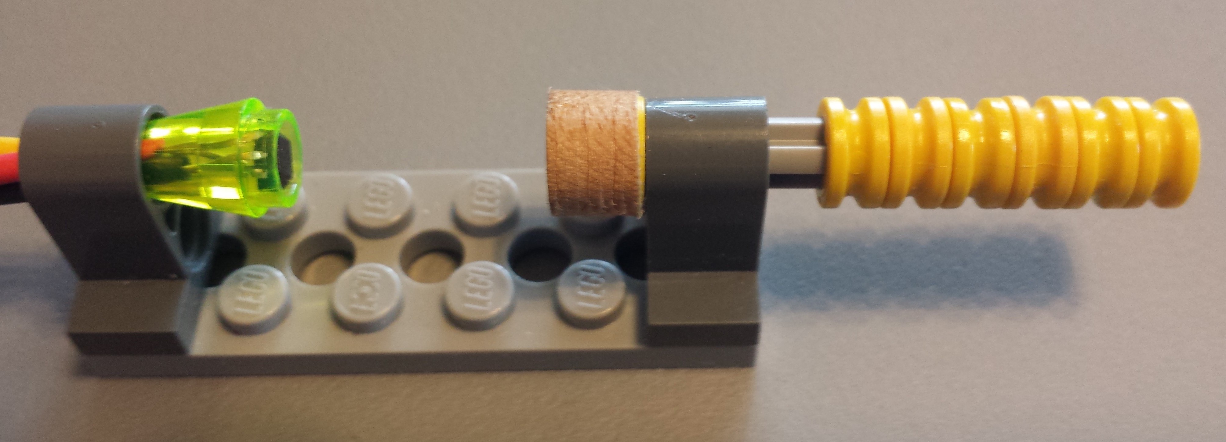
The Experiment was set up as seen in this image
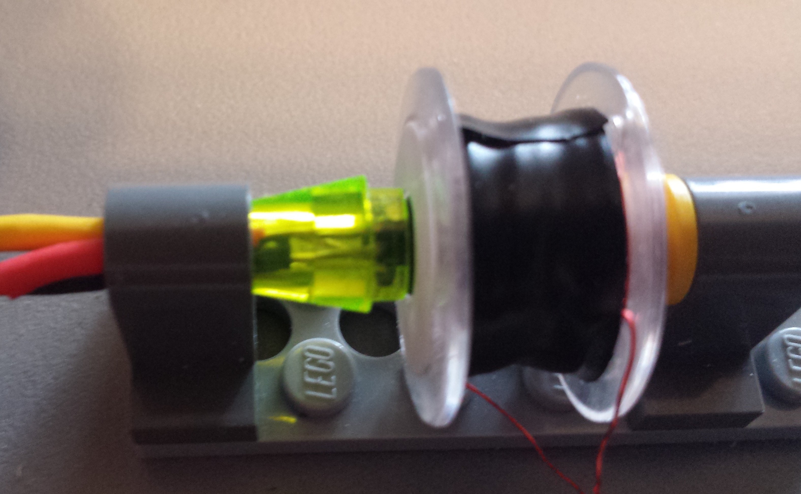
Because I was limiting the current some of the lower end counts were at a disadvantage but even short bursts at the full current that would be pulled would have melted the plastic at the very least. Even with that though I think some interesting conclusions can be drawn.
The next update will be of the dc motor, with what I think will be the final new component: the commutator!
Discussions
Become a Hackaday.io Member
Create an account to leave a comment. Already have an account? Log In.