 Thierry
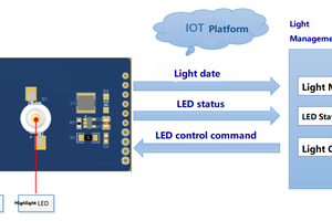
This project is inspired by the fact that LEDs can be used to emit and measure light levels. Sending data with an LED is easy, just flash it in a certain manner. Receiving is a bit trickier. By reverse biasing the LED and measuring the discharge, the flashing signal can be received.
- Very Low-Cost Sensing and Communication Using Bidirectional LEDs http://www.merl.com/publications/docs/TR2003-35.pdf : Synchronized communication, range 3cm, 250 b/s
- An LED-to-LED Visible Light Communication System with Software-Based Synchronization http://people.inf.ethz.ch/schmist/papers/OWC12.pdf: Synchronized communication, Manchester encoding, range up to 10cm, throughput up to about 250 b/s
- LED-to-LED Visible Light Communication Networks https://www.disneyresearch.com/publication/led-to-led-visible-light-communication-networks/: As above, but range up to 2.3m, throughput up to 800 b/s
It is obviously possible to achieve VLC using LEDs only (Always a bit of a disappointment to see that something has been done before. Well, what has not). Still, my goal is a bit different. All existing systems use some clever synchronization system, full development boards, and power consumptions of typically 200 to 300 mW. My goal is a system that does not require synchronization, is based on a minimal number of components, and uses much less power.
Transmission
Data transmission is straightforward: Transmission is initiated by sending a start byte (1 = light, 0 = no light), followed by Manchester encoded data and an end byte. The start byte is no valid Manchester bytes on purpose.
- Start byte: 11101000
- A special data byte, Manchester encoded, containing the length of the following data stream and additional meta information
- Data, Manchester encoded
- End byte: 01010101
The result of these simple choices is not only that the transmitting LED appears to have constant luminosity. The transmission can also be checked for sanity by testing the received signal for correct Manchester code and for correct end byte received after the expected data length. I guess that adding a checksum to the payload would not add much for error detection. Let's test that later maybe.
Transmission rate will probably end up in the range of 1000 b/s.
Side-note on dumping the resistors
In the pursuit of a simplistic circuit, I dumped the resistors on LEDs some time ago and attach them directly to the microcontroller. I know that this is a reason to shout at me for some people, but there's no need to. Just look at the datasheet. At 3V, the two I/O pins combined have an internal resistance of 70 Ohms. My yellow LEDs draw 14 mA. That is well within spec for the pins.
Reception
The receiver is set up to measure the discharge of an LED that is repeatedly reverse biased. In order to circumvent synchronization, the signal is oversampled by a factor of two. With the transmission rate of 1000b/s, this translates nicely to running the microcontroller at 1MHz and an 8-bit timer without prescaler for timing.
This leaves a mere 256 ticks for the sampling and analysis. The timing works as follows:
- Count 0: Start ADC
- ADC complete: switch on LED if wanted, Analyse signal
- Count 140 (approx.): Reverse bias LED for next measurement
The ADC runs as fast as possible with left shifted result. Only the upper 8 bits are used.
 RT-Thread IoT OS
 Grayson Schlichting
 ClockLoop
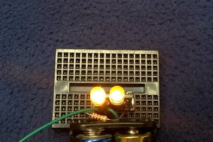
by using a NE 555 timer we can increase the blinking of LED
Hence more the blinking more the data transmission