TheotherMike
Nice things:
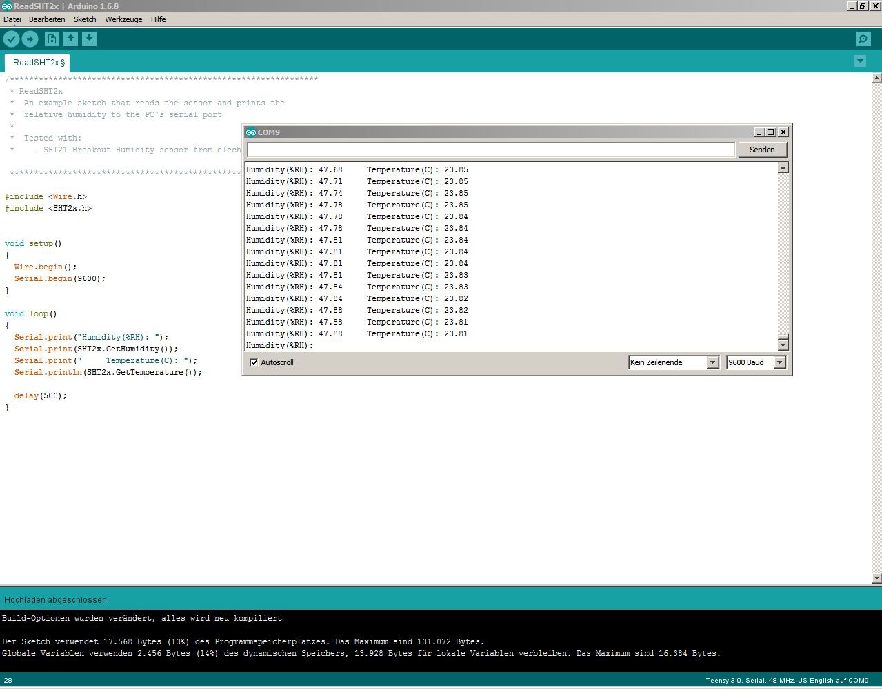
The nice thing about a humidity sensor is, that only two Parameters are given out:
- Temperature (In fact a voltage measurement of a Silicon bandgap...)..
- Relative Humidity (In fact it´s a capacity which is measured physically...).
But several more can be calculated out of them:
- Dew Point.
- Spread.
- Cloud base height.
- Absolute humidity within surrounding air.
- ( Heat index /comfort zones which are very subjective !).
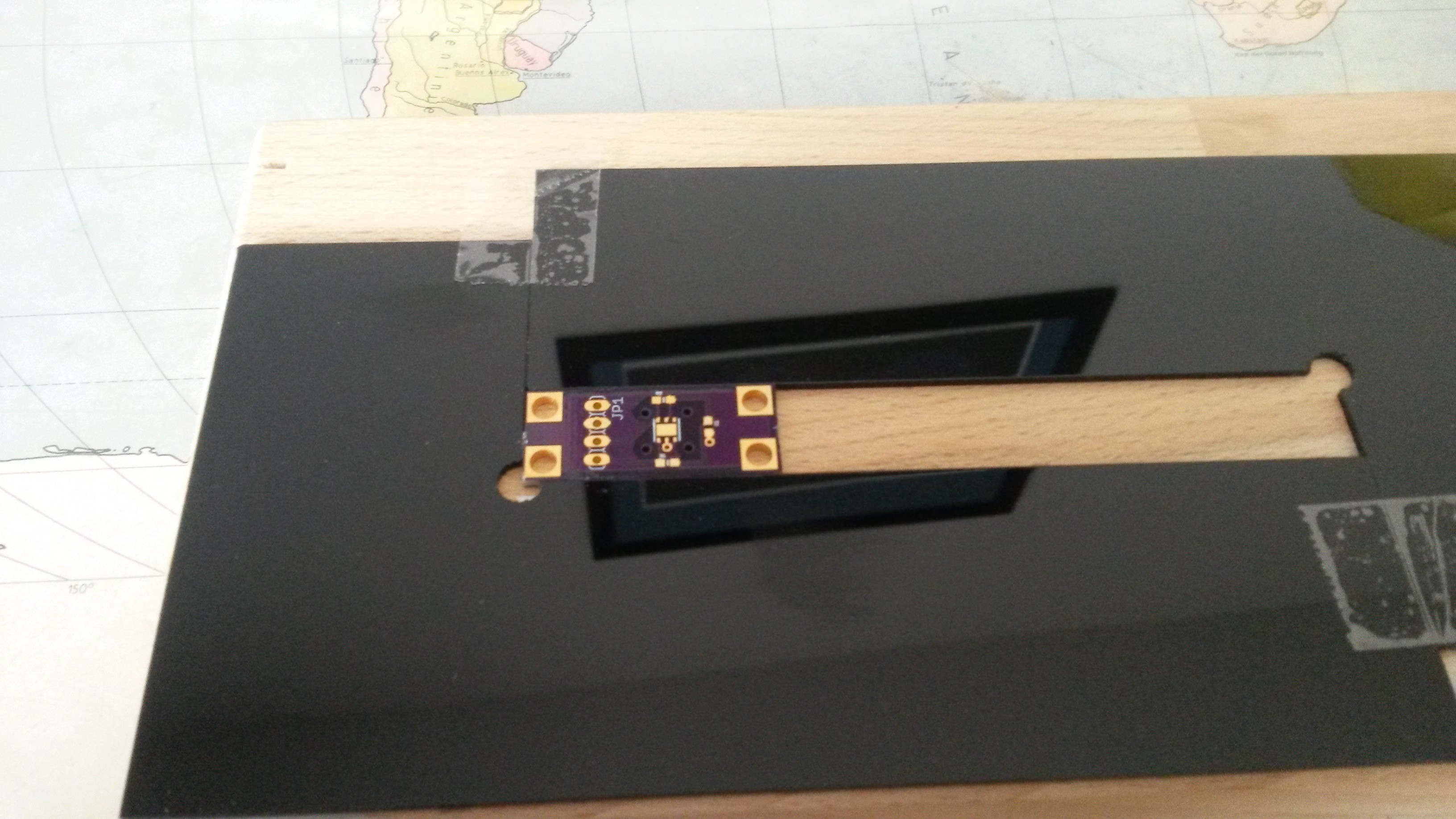
SHT21:
The SHT21 has some Advantages (despite ist higher Price and complexity) over the well known DHT11/22/AM2302 sensors: faster, smaller and can be equipped with a filter cap. OK, smaller is not that correct regarding the needed housing etc., but opening holes in a portable case can be made much smaller than the size of a DHT housing.
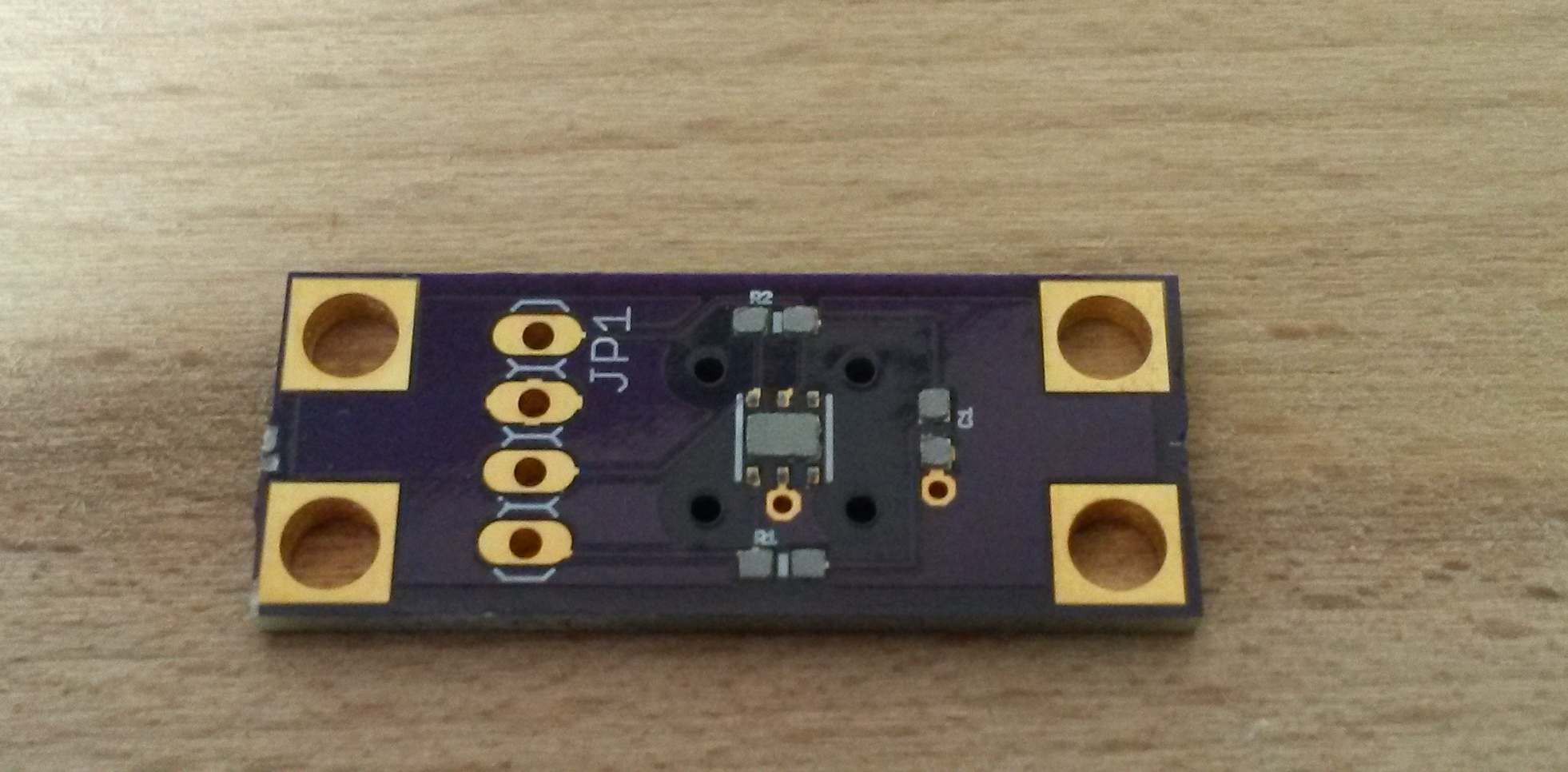
PCB should be easily mountable and filter cap should protect the sensor from particles etc. when using the device outdoor.
Sensirion, the sensors manufacturer has two nice Whitepapers about humidity which explain many things quite nice.
I will give a Brief summary of the context I´m interested in:
Relative Humidity:
Hot air can contain much more water than cold air. Relative Humidity will therefore only give a degree of Saturation at a given temperature.
Depending on surrounding temperature, and therefore state of water, one has to differentiate two cases:
- Above (liquid) water
- Above Ice.
The Saturation vapor pressure can be described by the Magnus formula:
Parameters above are liable above liquid water, which in turn means that below 0°C liquid water must be supercooled (no condensation seeds...).
Above ice, parameters change to:
Dew Point:
Dew point is the temperature to which the air must be cooled down to achieve condensation of contained moisture. With constants above, the dew Point can be calculated as follows:
Spread:
Spread is simply the difference between measured temperature and dew Point:
Adiabatic temperature Gradient:
In atmosphere, an upwards moving volume of air cools down. Temperature gradient can also be calculated and measured as well. There are two conditions which can be distinguished:
- Dry adiabatic (no condensation, dry air,...): 9.76 K/km
- Wet adiabatic (condensation occurs and "heats" the air ): 6.50 K/km
Unfortunately, the wet adiabatic temperature Gradient depends on temperature and can range between 4 - 9 K/km. A value of -6.50 K/km is an "european average".
Nevertheless, in reality values between 6.5 - 13.5 K/km can be found !
Cloud base Height / Ceiling:
A volume of air can be cooled down until its temperature reaches the dew Point at which condensation occurs. The lower cloud base height can now be estimated by dividing the Spread with the adiabatic temperature Gradient. In meteorology a typical value of 8 K/km is used ("Henning equation"):
So, when "measuring" a Spread of 13K, ceiling height should be around 1625 m above you.
Disclaimer:
You shalt not fly your wingsuit only on the Basis of a cloud base height calculation performed with a ~5USD sensor!!
All formulas above are correct in Terms of science, but their results are estimations. Weather is totally complex and so several things are neglected (pressure dependencies, convection, Inversion, temperature gradients,...). Nevertheless, those Basic Parameters are worth to study although we look at them on a very Basic Level. After all, with proper Firmware and reliable measurements a humidity sensor is a great tool for indoor/outdoor activities.
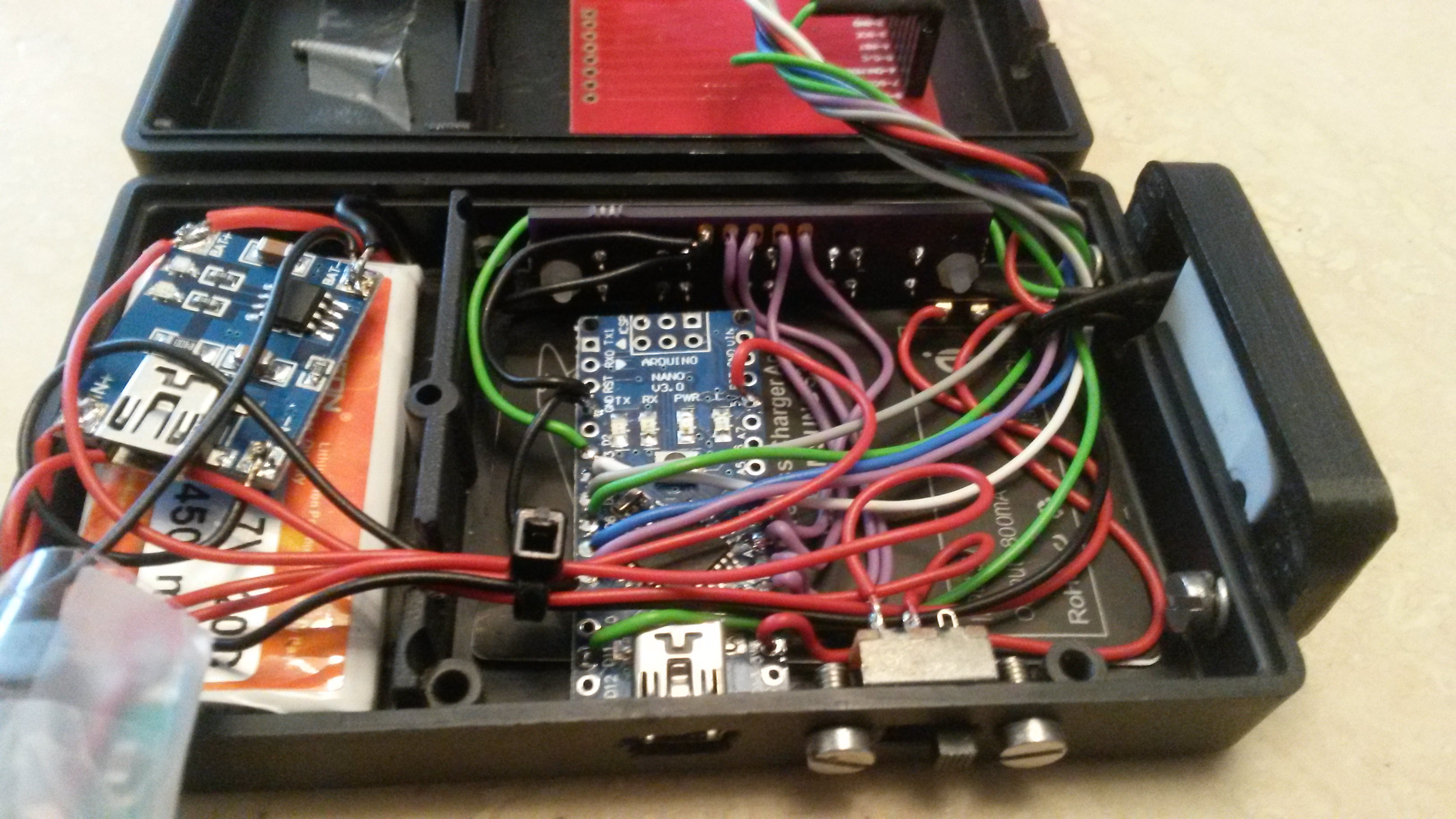
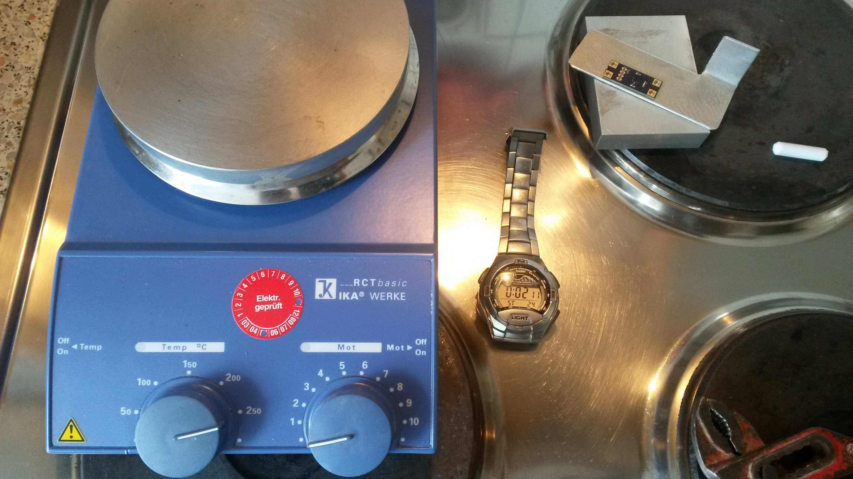
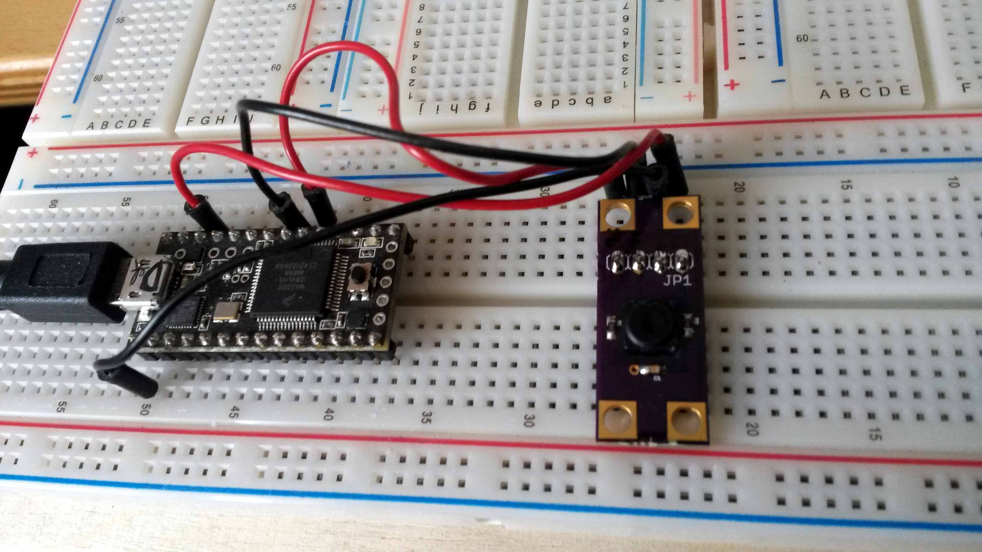
This is my first try to set up a pcb, soldering with smd parts, using a stencil, making µC read data.
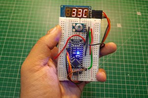
Goal is to display at least rel. Humidity and eventually calculate some further parameters within a portable case (might be a further HAD-Project....).
 It works quite OK using u8glib and currently there´s nothing more implemented than reading out the humidity, temperature and displaying the calculated dew point, heat index and ceiling height. It´s really nothing special but already makes fun carrying it around checking local conditions. At the moment, it only can be switched on and it immediately starts displaying the values. --> "KISS".
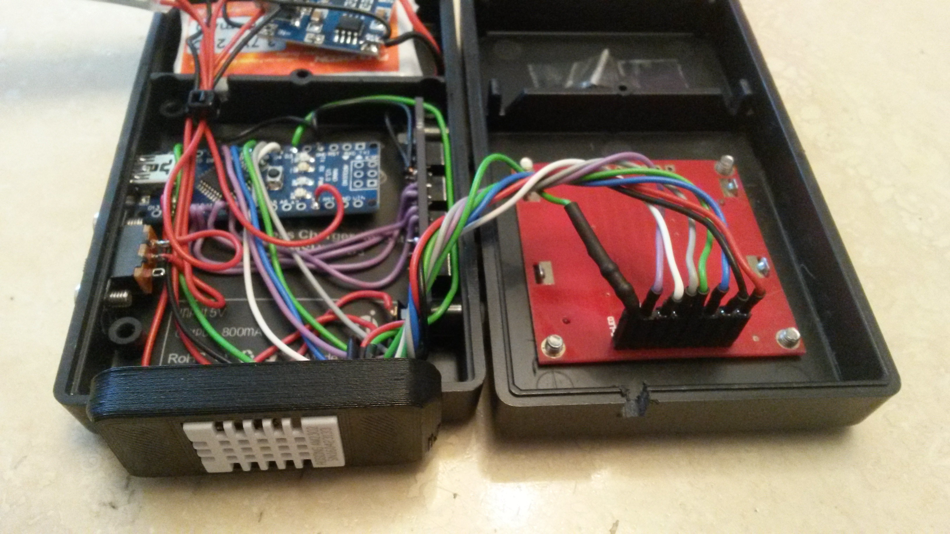
 Darren Blaxcell, aka Pork
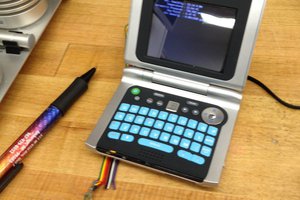
 Beaglebreath
 Lithium ION