0%
0%
Bi-Copter V2
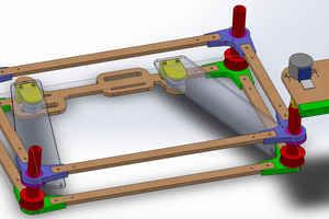
The objective of this project is to design a frame for an RC Bi-Copter in CAD with laser cutting in mind
 Spencer
Become a Hackaday.io member
Already have an account? Log in.
Just one more thing
To make the experience fit your profile, pick a username and tell us what interests you.
Pick an awesome username
hackaday.io/
Your profile's URL: hackaday.io/username. Max 25 alphanumeric characters.
Pick a few interests
Projects that share your interests
People that share your interests
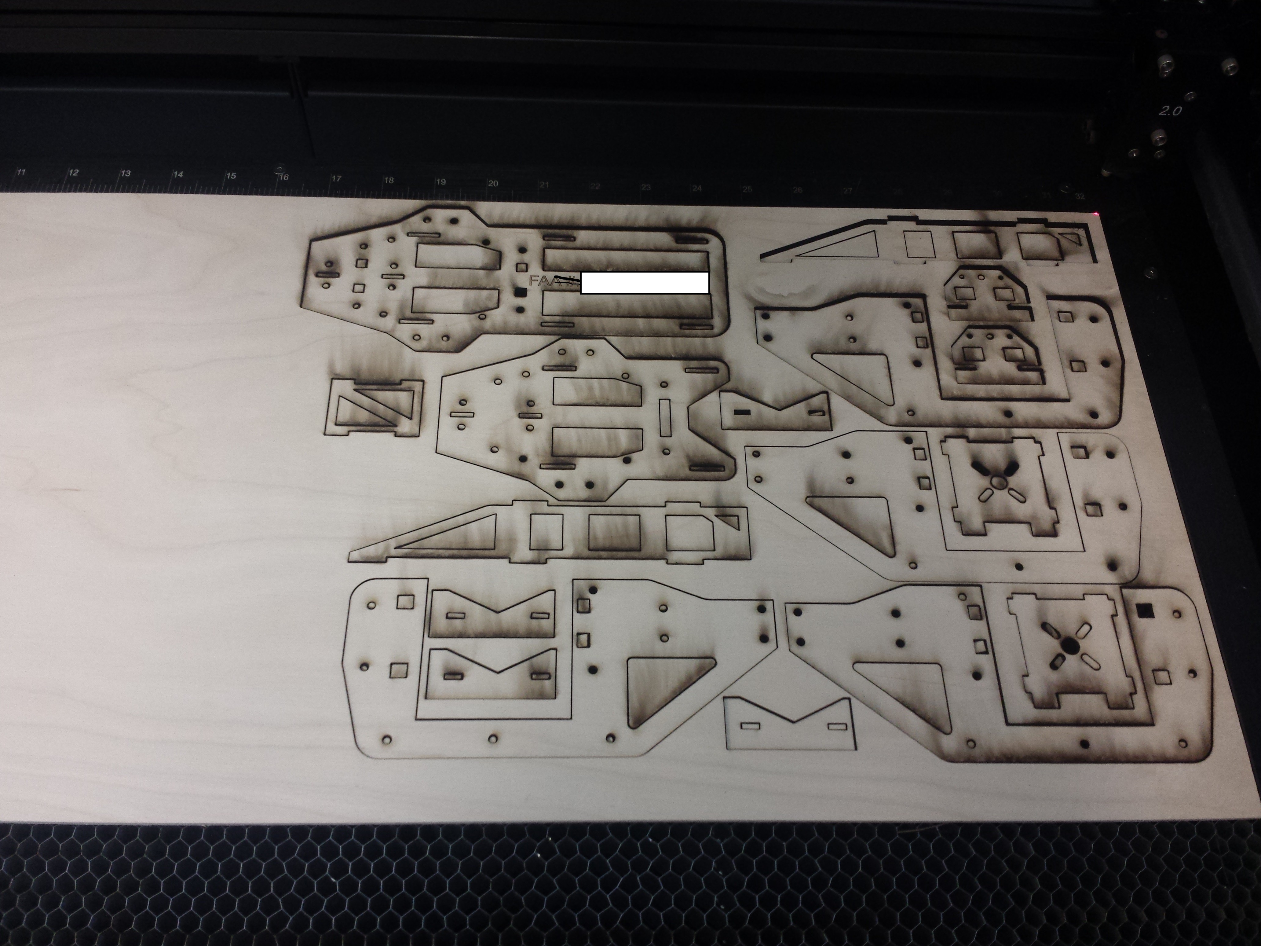
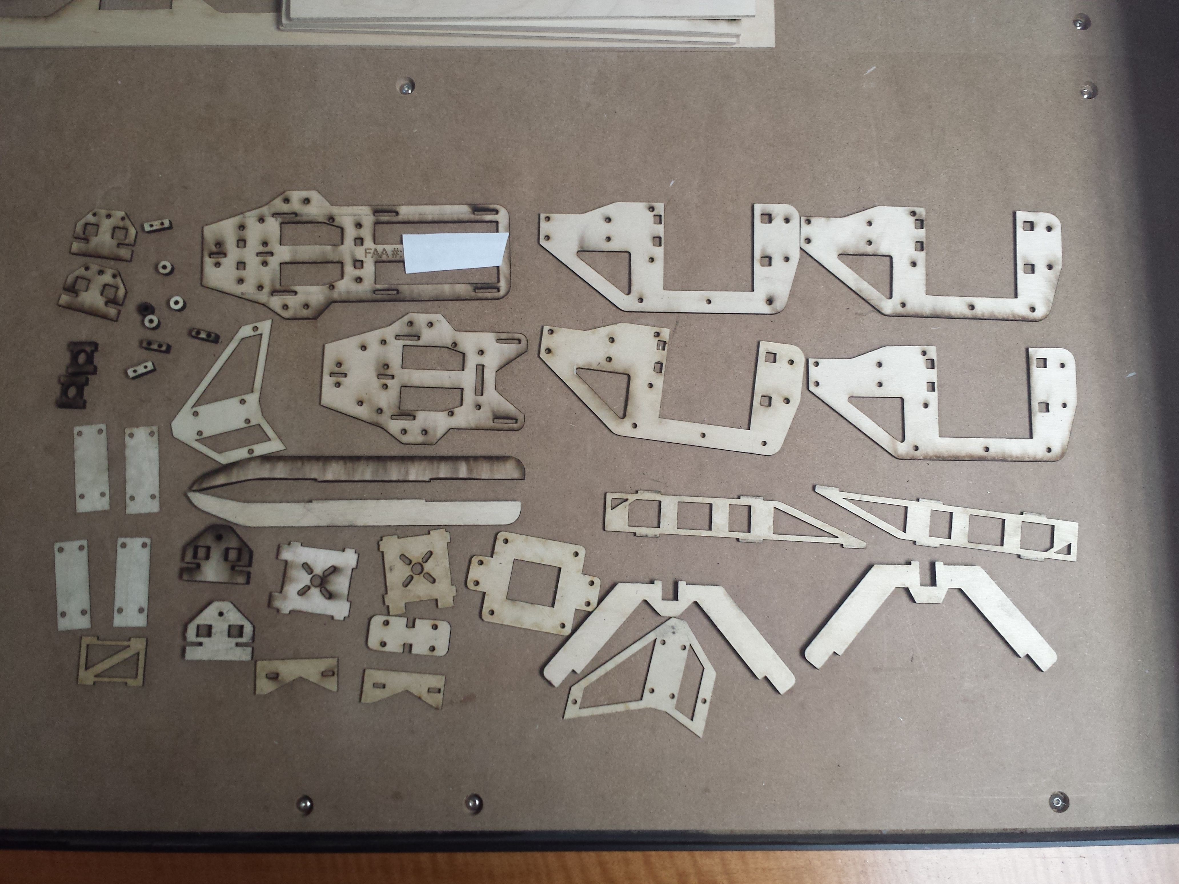
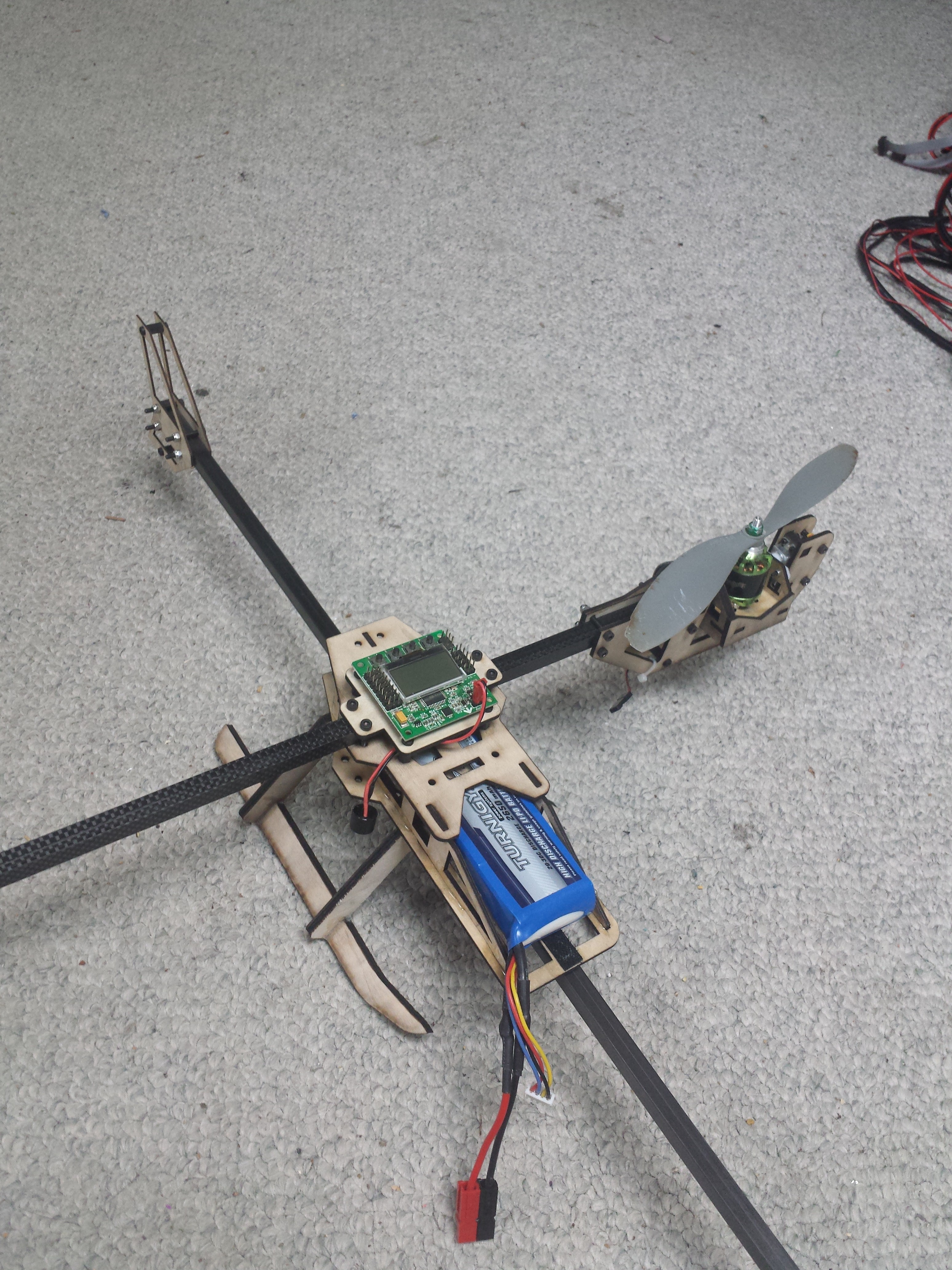
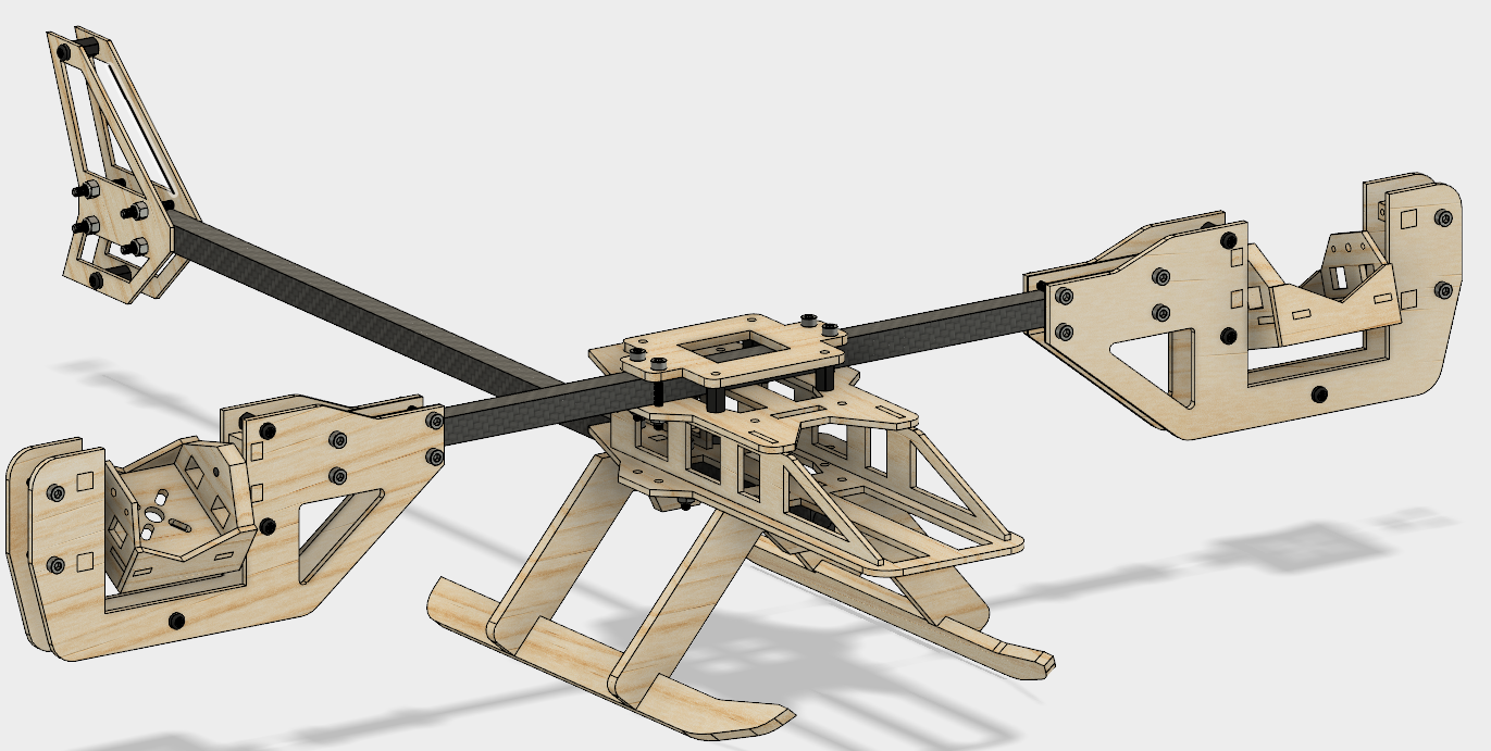 The nice thing about fusion is I can input material density and get a weight estimate. This frame comes in at around 285 grams. Not bad, I could probably do better with carbon fiber or fiberglass but that stuff is a royal pain to work with. The plan is to laser cut the plywood then bolt/glue the frame together. I tried to keep the glue to a minimum. The less glue the simpler to repair and Bi-copters crash A LOT. There not too practical but still fun. The black spars are 10mm carbon fiber spars from Hobbyking. Cheap and light while being strong enough. 10mm is likely over kill for a craft of this size anyways.
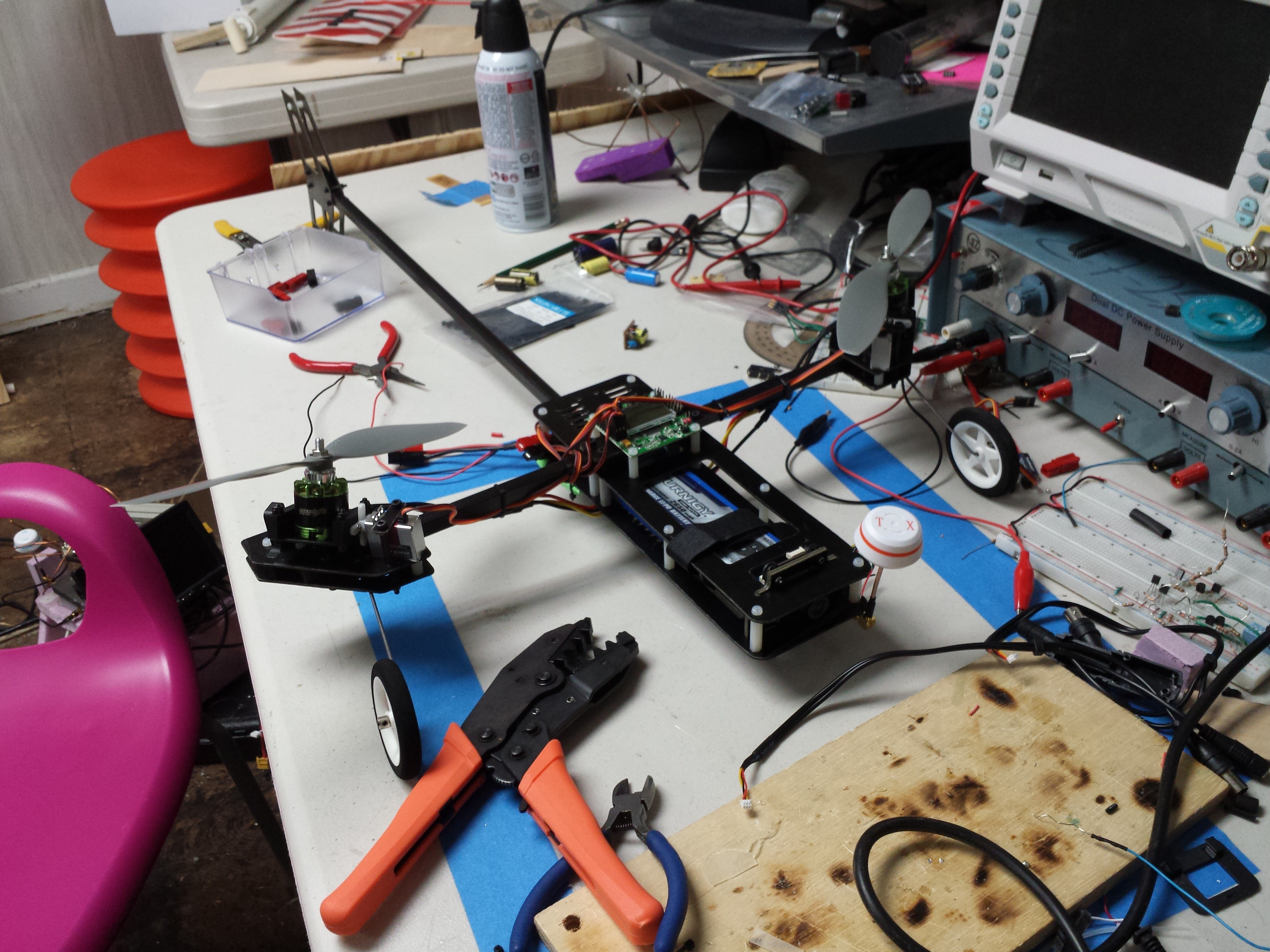

 Timo Birnschein
 Andy Forest
 tjltjl
 Daren Schwenke
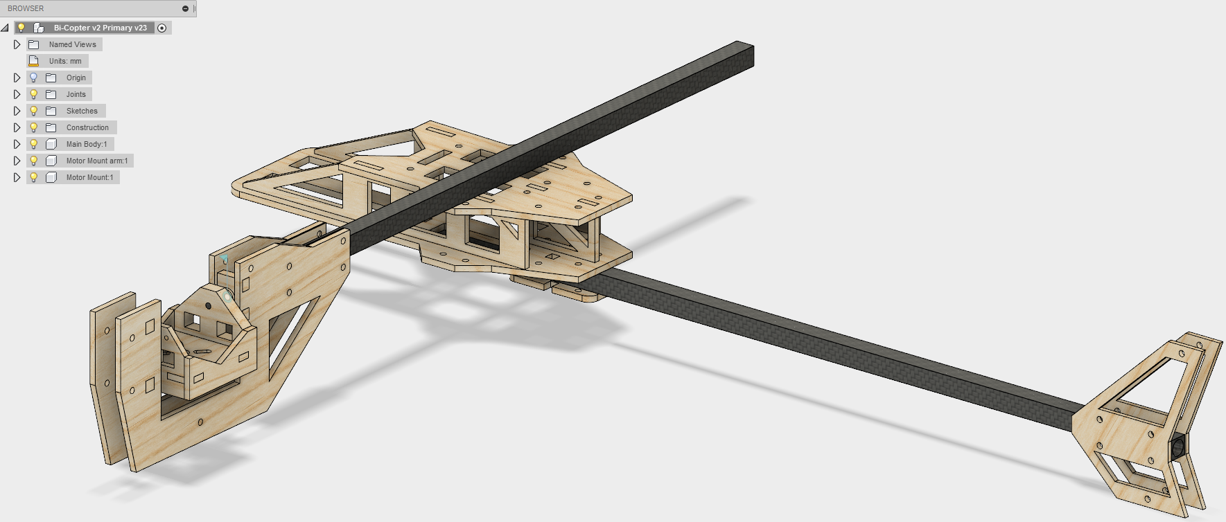
Any chance you have the DXF or DWG files from the fusion file? I just need the 2D for cutting. Thanks.