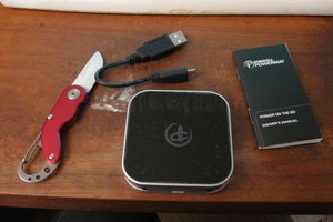
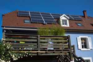
Living close to the sea yet in the shadow of some large hills, I am looking to increase my AIS reception coverage by placing a solar powered AIS receiver on a prominent hillside and relay AIS sentences back home via a LoRa RF datalink.
The LoRa broadcasts could be used by other people in the vicinity for their own needs.

 Michel Kuenemann
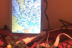
 Mr. Spriggs
Steve, this is a great project! I hope you were able to get over some of the hurdles you listed. How is it going?