 Allen Mamaril
The glucometer is based off the following design:
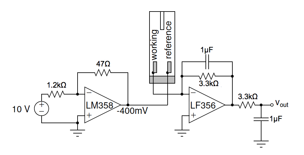
The component values were as follows:
R1 = 3 kohm
R2 = 1.2 kohm
R3 = 100 kohm
C = 0.03uF
The resistors R1 and R2 were chosen such that the reference electrode was about -400 mV with respect to the working electrode. The gain was calculated to be:
gain = -(R2/R1) = 1V / 0.400V = -0.400
At the output of the circuit was a band pass filter to remove unwanted frequencies and any noise. The low pass filter at the output of the circuit was designed to have a corner frequency of 53 Hz using the formula 1/(2*PI*RC) = 1/(2*PI* 100 kohm * 0.03 uF).
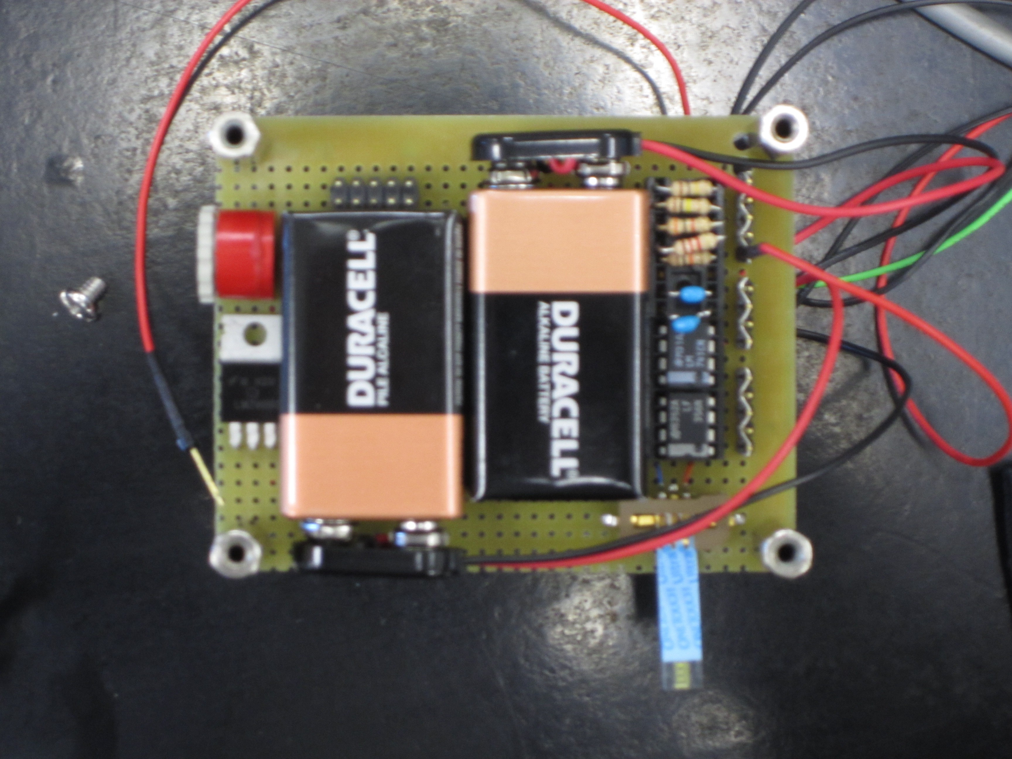
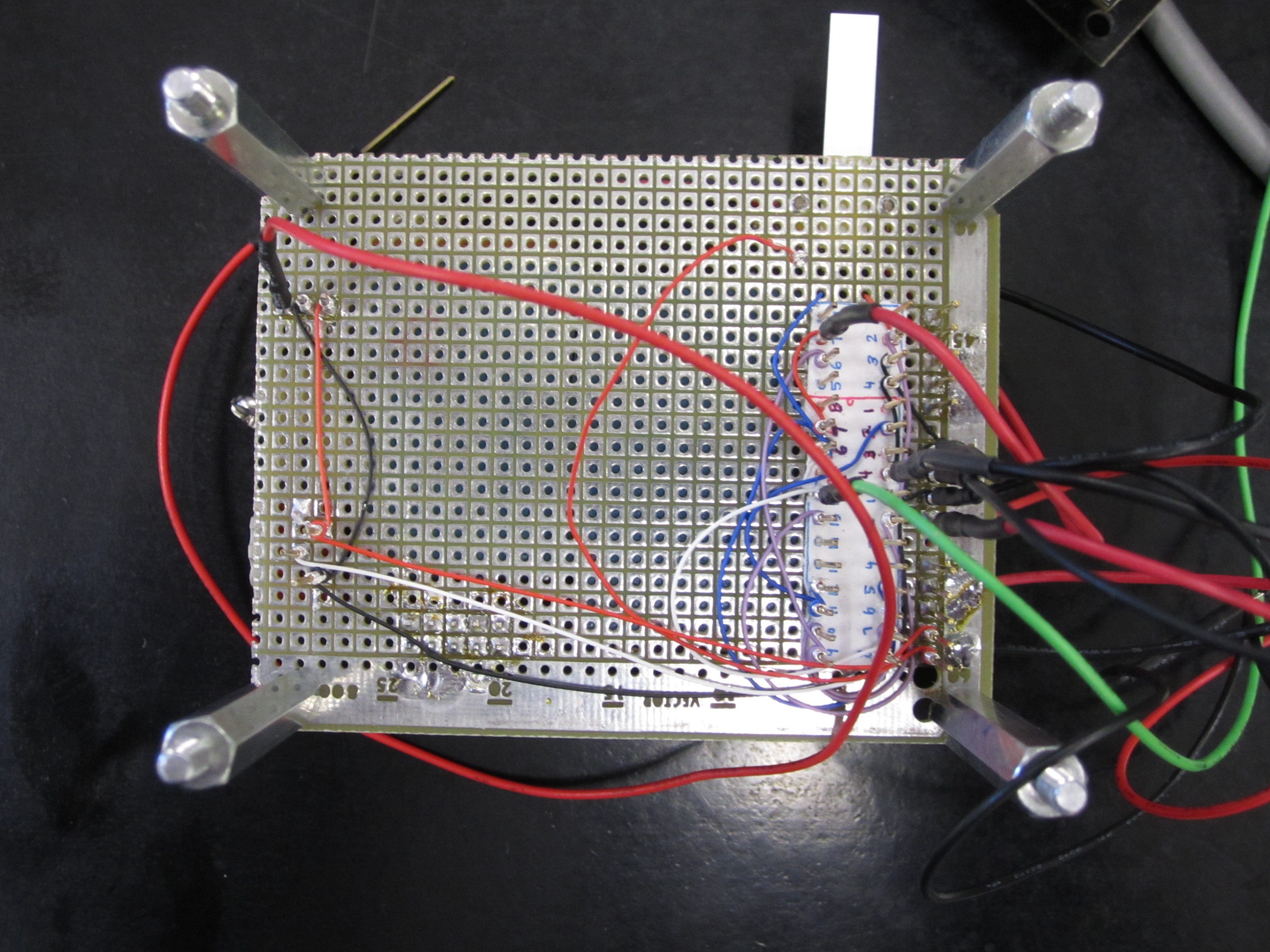
This was how finalized the layout of the hardware components on the perforated board.
In order to interface the microcontroller with the glucometer circuit, an analog digital converter (ADC) is needed to read the data from the analog circuit and convert it to digital data to store in the SD card. A driver is written for the ADC using pin 5 of JMP4 as the input pin. There is a task for the ADC where the ADC will continuously grab data from the ADC input pin.
For the glucometer, samples are only needed to be taken over short period of time. In this case, data will be sampled over a period of 15
seconds. A button on the microcontroller can be pressed to start the sampling.
When the button is pressed, the microcontroller will give the user five seconds
to get read to put in the blood sample. The user should put the blood sample at
zero seconds. The LEDs on the microcontroller will act as a countdown meter so that
the user will know when the sampling is done. For the button function, a controls task is needed so that the
micontroller will continuously monitor the buttons for any input. Since the
buttons and LEDs are used, this means that the port expander has to be
initialized. When the blood test is done, the maximum value of the blood sugar
level will be compared with the minimum and maximum threshold. If the blood
sugar level is not an ideal level, then the microcontroller will play an mp3 sound.
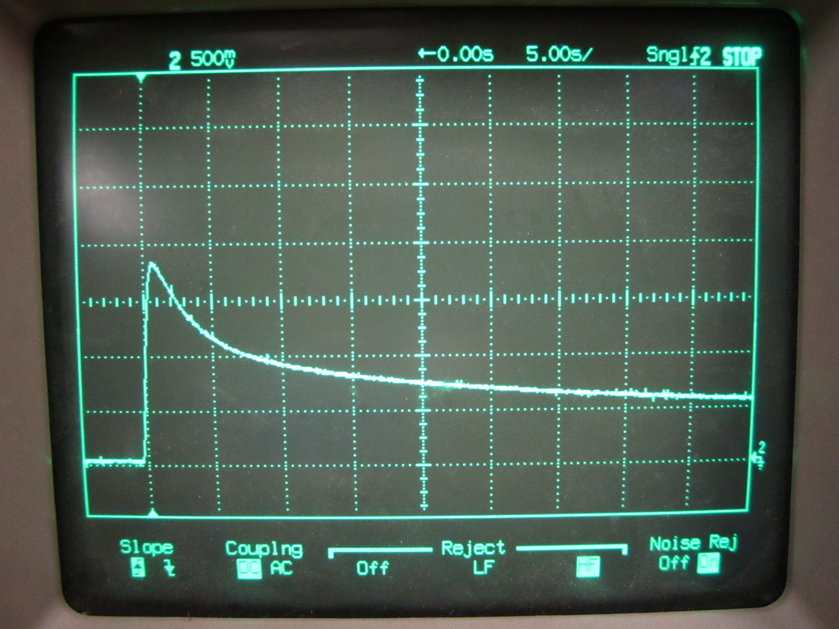
The glucometer circuit was tested module by module. The first inverting op-amp is tested to make sure that it gives the correct output (- 400mV). Then, it is connected to the second op-amp circuit, which is a band-pass filtering circuit and the output of that is tested. The output of the whole glucometer circuit is connected to an oscilloscope.
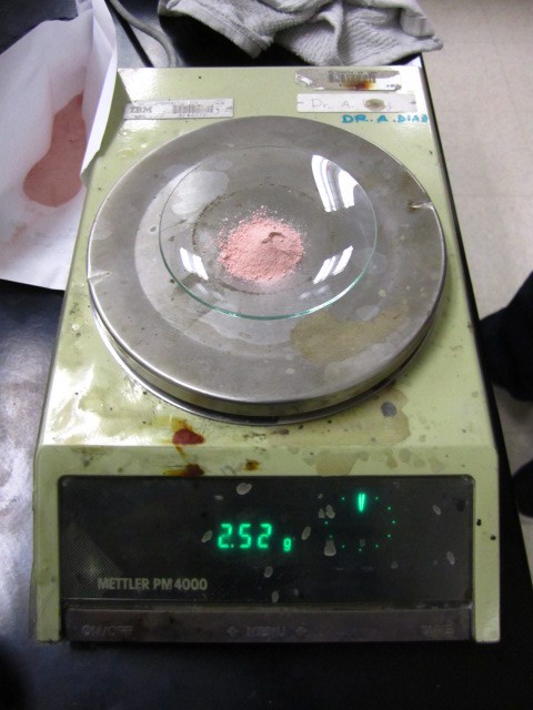
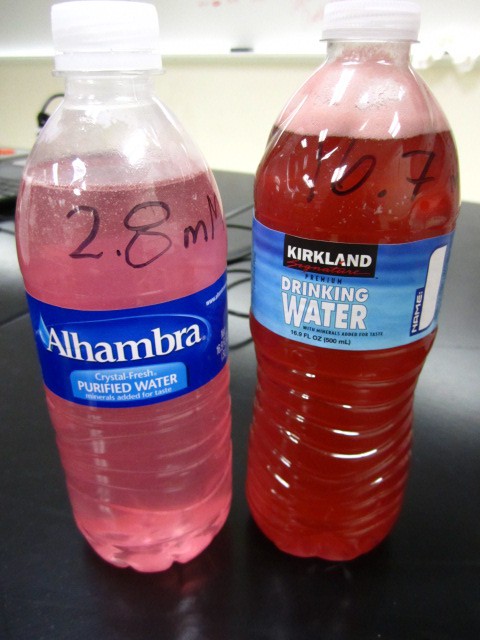
In addition, we prepared two solution of glucose at 2.8mM and 16.7mM. Concentrations below 3.9mM (70mg/dL) or above than 10mM (180mg/dL) are considered to be hypoglycemic or hyperglycemic, respectively. Using these concentrations, as specified in the lab protocol, allows for analysis of the full range of biologically relevant concentrations. To prepare the solutions, we mixed the required amounts of crushed glucose tablets with distilled water.

Once the LPC2148 board was tested
as functional with the ADC connected to the potentiometer and with the data
writing into a file, the glucometer circuit output is connected to the ADC
input. When the glucometer circuit and the LPC2148 board are connected
together, the output will be written to the file. An oscilloscope is also
connected to the output of the glucometer circuit (figure 6). The graph on the
oscilloscope and the graph on the file should be identical. In this testing
purposes, the result was valid.
While our circuit is a simplified version of a potentiostat found in modern glucometers, it allowed meto successfully exam and understand the core electrical principles behind a glucometer. The hardest part of this project is writing the driver to the ADC and building the glucometer circuit. Since this project is built on the MP3 project, the I2C bus, SPI bus, UART, and port expander have already been initialized, and they can be used freely with the added glucometer circuit and ADC. The circuit required lots of debugging and checking that the correct wires were connected since. This was due to moving the parts from a bread board to a perforated board.
 Hulk
Hulk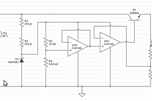
 Doug
Doug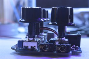
 Grant Giesbrecht
 Discrete Electronics Guy
Very interesting, I am working on a similar project if someone has documents to help please send ! bryancheong@hotmail.fr