Close
0%
0%

Vintage Toy Synthesiser

A wooden toy piano converted into a standalone digital synthesiser.

Similar projects worth following
A vintage wooden toy piano converted into an open-source, standalone polyphonic digital synthesiser.

The primary goal of the project was to - while operating as a fully working synthesiser - allow the device to retain the existing charming aesthetics and physical character of the toy piano, carefully designing any new elements of the object around this goal, so this was just as much an art & design project as it was a music technology and engineering project.

This project was originally carried out as part of the Element14 Music Tech design challenge 2016, and it ended up becoming the winning project.

Primary Features

  • 2-voice digital synthesiser with true polyphony
  • 5 oscillators with dedicated waveforms
  • State-Varible-Filter with independent LP, HP, BP and Notch mix controls
  • Amplitude and Filter ADSR envelopes
  • Two modulation sources (LFO and keyboard velocity) with three destinations, each with independent bipolar depth controls
  • Digital distortion FX
  • Changeable scales on the keyboard
  • ‘Vintage’ parameter for replicating old/broken analogue synth voices
  • Full MIDI I/O integration
  • Polyphonic Aftertouch expression (MIDI-out only)
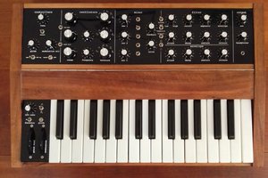
  • Charming miniature grand piano form

Development Specs

  • The brain and sound engine of the synthesiser are seperate Linux applications running on a BeagleBone Black board (a requirement of the Element14 Design Challenge), which communicate via software sockets. The brain application is developed in C, and the sound engine application is developed in C++ using the Maximilian Audio DSP library and RtAudio. See the BeagleBone Black directory in the GitHub repo for the code for these applications.
  • The keyboard and panel use Arduino Pro Mini boards for sensor/control scanning. The Arduinos communicate with the BeagleBone Black via serial. See the Arduino directory in the GitHub repo for the keyboard and panel code.
  • The keyboard mechanism uses homemade pressure sensors made out of Velostat.
  • There is a Mac OS X editor application for saving and loading patches on the synth, written in C++ using the JUCE framework. See the VtsEditor directory for the code.
  • Completely open-source.

For more info on the software architecture see here.

Videos

Project Outline

I’ve got a certain fascination with vintage wooden toy pianos - there’s something so aesthetically-pleasing and charming about the miniature form factor and clunky keyboard mechanism. Because of this I’ve ended up taking part in a number of different toy piano projects, therefore the Vintage Toy Synthesiser came about as an evolution from a number of past endeavours.  

The roots of the project started with an experimental toy piano sampling project with my brother Ali Lacey, which eventually became the Impact Soundworks Curio: Cinematic Toy Piano Kontakt instrument; followed by a project I did at MIDI HACK 2015 where I turned a toy piano into a basic USB-MIDI controller. I felt like the next logical step in this series of projects would be to attempt to convert the piano into a standalone synthesiser; an idea inspired by my day job at Modal Electronics. One great thing about this particular project is that it allowed me to combine what I do at my day job with my ‘out of hours’ activities/identity as a music tech maker/hacker.  

My main aim of the project was to allow the existing key mechanism and enclosure of a vintage wooden toy piano to act as a fully functional standalone digital synth. I didn’t set out to create anything revolutionary or premium in regards to the synthesis engine or control interface; in fact I wanted these elements to remain ‘vintage’ and fairly simple akin to the existing instrument - a classic subtractive synthesis engine with standard oscillator waveforms, using just regular dials and switches for controlling the parameters. My main focus was making sure that the synth would retain the existing charming aesthetics and physical character of the toy piano, carefully designing any new elements of the object around this goal, so this was just as much an art & design project as it was a music technology and engineering project.

Old objects like this are sometimes discarded or thrown away because their functionality is now seen as being inferior to their modern day versions, however there is a special quality...

Read more »

  • 1 × Wooden Vintage Toy Piano
  • 1 × BeagleBone Black
  • 5 × DIP24 0.6" IC socket
  • 1 × 1N4148 Diode
  • 1 × BeagleBone Proto Cape

View all 25 components

  • The End Result

    Liam Lacey09/02/2018 at 21:15 0 comments

    (Original post date: 09/04/16)

    So this is my 17th and final log for my music tech design challenge project, and for it I have created three new videos talking about and demoing the end result of the project:

    1. A specification overview video, outlining all the features of the synth as well as briefly discussing the overall development of it and how it works
    2. A complete walkthrough video, demoing in detail each control and parameter of the synthesiser
    3. A video on how the device can be used as a MIDI controller

    I've also included the demo sound video that I posted a couple of weeks back, as that video is a great example of the range of sounds that the synth can produce, as well as some new higher-quality photos of the synth.

    Specification Overview Video

    This video briefly goes over the specifications and features of the synth from both a user and development point-of-view.

    Complete Walkthrough Video

    This video is an extension of the last video, and in detail talks about and demos each control and parameter of the vintage toy synth. I apologise that the video quality isn't great and that you can't quite make out all the text on the panel, however hopefully I explain in enough detail what I am doing as I go along for you to make sense of it. Also it was produced to demo how each control/parameter effects the sound, rather than how to create a great sounding patch, so please don't judge the sound capabilities of the synth based on the fairly average patches that I produce in this video.

    Sound/Patch Demo Video

    I first posted this video a couple of weeks back, however it is a perfect example of the types and range of sounds that you can create with the final state of the vintage toy synth, so I thought it would make sense to include it here as well. This video also demonstrates the use of the VTS Editor - a desktop/laptop application I developed for the synth for adding patch saving and loading capabilities to the instrument.

    MIDI Controller Video

    While the previous videos demonstrate the instruments primary function as a standalone synthesiser, this video shows how the device can be used as a MIDI controller. The video demos the synths MIDI capabilities with Logic Pro and Ableton Live, however the device could theoretically be used to control any external MIDI software or hardware.

    Photos

    Below are some high-quality photos of the final state of the vintage toy synthesiser.

    vintage toy synth 1

    vintage toy synth 2

    vintage toy synth 3

    vintage toy synth 4

    vintage toy synth 5

    vintag toy synth 6

    vintage toy synth 7

    Final Development Material

    All the final code, circuit diagrams and design files for the synthesiser can be found in the projects Github repository.

    Conclusion

    I've spent the majority of my free time over the past 3 and half months working on this project, and I couldn't be happier with the result. My skills in both software and hardware development have dramatically improved thanks to this project, and even though it's been a lot of hard work and very stressful at times, it has overall been a very fun experience. I hope those of you who have been following the project have enjoyed what I've done, and please feel free to leave any questions below.

    Thanks!

  • Fixing-Together and Refining the Enclosure

    Liam Lacey09/02/2018 at 21:00 0 comments

    (Original post date: 03/04/16)

    In order to undertake this project I had to completely take-apart the toy piano, unfortunately slightly damaging it in the process due to the way it was originally connected together. As all the electronics for the project are now finished, I spent this week putting the piano back together as well as adding some small extra touches, some to make the synth easier to use though some just to improve the aesthetics of the design.

    vintage toy synth grand piano style

    The finished enclosure of the vintage toy synthesiser, propped open like a grand piano

    Attaching the Panel

    Instead of securing the synth panel to the top of the piano enclosure in the original standard way, I decided to connect it in a way so that the top of the synth could be opened like that of a real grand piano (see image above). I chose to do this for a couple of reasons:

    1. It improves the charming miniature form of the toy piano, a characteristic of the object that I didn't want to lose in the conversion.
    2. It gives it a great modular-synth-esque look, exposing all the colourful wires and flashy LEDs of the microcontrollers.
    3. It allows me to easily get into the synth for development and repairs

    To do this I added 8 miniature hinges to the top-left-underside of the panel, using screws to attach the hinges to the wooden side, but unfortunately having to use superglue to attach the hinges to the acrylic panel due to the screws being too brittle for the tougher material (I prefer screws so things can be easily taken apart again if needed).

    vintage toy piano hinges

    The hinges attaching the panel to the enclosure

    Back Labels

    A couple of weeks ago I posted a log about the sockets and controls I've added to the back of the synth, and this week I added some labels to the sockets/controls so that the user knows what each socket/control is for. I made these labels using gloss white filmic sticker sheets, using text of the same font and colour as that of the front panel on a black background, in the hope that it would look as similar as possible to the panel for continuity without being able to apply the same laser-engraving method to this part of the synth. Unfortunately I don't think they look quite as professional as the text on the panel, and I'm probably going to recut and reposition them before the end of the project so that they look a bit neater, however they're not highly visible and are mainly there so that I can remember which MIDI socket is MIDI-in and which is MIDI-out!

    vintage toy synth back panel

    The finished (-ish) back panel

    Keyboard Gap Covering

    The original toy piano enclosure came with a strip of blue fabric (possibly velvet) draped above the keyboard to hide a fairly large gap into the pianos body. Unfortunately I made the mistake of removing and misplacing this fabric, however on the plus side it gave me the chance to experiment with different types and colours of material to use for the synth. After trying out various colours of both ribbon and felt, I settled on using a burgundy ribbon as a replacement. I chose a burgundy colour as I felt it matched with the red on the front of the keyboard keys but without being too garish, with the glossy/shiny aspect of ribbon going well with the rest of the glossy enclosure. Below are a couple of photos:

    vintage toy synth keyboard gap

    The gap above the keyboard

    vintage toy synth ribbon

    A strip of ribbon used to cover the gap

    Painting

    The main thing that got damaged when taking apart the existing toy piano enclosure was the paintwork, so I needed to touch up the paint where this had happened. I also had to paint some new areas of the existing enclosure now that the front panel could be opened and expose some previously-hidden areas.After trying out a disastrous gloss black paint which destroyed the first synth panel I had produced, it turned out that gloss black nail varnish was the perfect tool for painting the enclosure.

    vintage toy synth painting

    Painting the synth with nail varnish

    Other

    A couple of other things I did to fix-together and refine the enclosure:...

    Read more »

  • Patch Manager Application and Sound Demos

    Liam Lacey09/02/2018 at 20:48 0 comments

    At the start of this project I wasn't planning on having any kind of sound/patch storage or management within the vintage toy synthesiser, however as the project progressed I was more and more finding the need to quickly save and recall patches for both testing and demoing the functionality of the sound synthesis engine. In the end I decided to implement an external desktop application to handle this.

    Approach

    Synthesiser patch management allows the user to save the sound parameter settings into a 'patch' so that a particular sound can be quickly recalled at a later time. It is a common features on commercial synthesisers, however I originally decided not to include patch management on the vintage toy synth for the following reasons:

    1. Patch management works best on synths that have relative or stateless controls (e.g. rotary encoders, which just increment or decrement a stored value in the backend) with an LCD for displaying control/parameter values, as opposed to absolute controls (e.g. potentiometers, which set a specific value determined by their position). This is because, unless you have motorised controls, loading a patch doesn't change the physical state of the controls, meaning that with pots it would cause them to be potentially complete out-of-sync with the backend. I didn't want to add an LCD to the piano as it would take away the vintage aesthetic of the object, as well as adding cost and implementation time to the project. Also I like the fact that with pots a user can glance at the panel and instantly see all the parameter values.
    2. Another reason an LCD is so important for patch storage is so that the user knows what number patch they are saving or loading. A minimal patch storage interface could be implemented using a set of toggle switches that represent patch numbers using a base-2 numeral system, however this would have involved an extra set of controls on the panel that I initially didn't think I could add, in regards to both space on the panel and connections to the Arduino Pro Mini.

    However as the project progressed I kept finding myself wanting to save the sounds I was able to create with the synth, which would make the device a lot easier to demo once finished. However by this point the front panel was already constructed so adding any extra controls on the synth was out of the question. However after giving it a bit of thought I realised that I could simply implement patch management in a separate external application that runs on a desktop/laptop computer which communicates with the synth via MIDI, which would work with the existing synth hardware. I therefore set about developing a Mac OS X GUI application using the C++ framework JUCE, and you can see the code for this in the project Github repo here.

    Having an external patch manager application isn't my preferred solution as it means you'll always need a computer with a MIDI interface to save and load patches, however from an interaction design perspective it could be considered a better implementation over adding an LCD to the synth. I recently attended MiXD 2016, a music interaction design symposium hosted by Birmingham Conservatoire's Integra Lab research group, where keynote speaker Jason Mesut stated that it could be considered inferior to add costly and complex LCDs and displays to products such as digital musical instruments when most of us already carry smartphones/tablets/laptops with us at all times - devices that can easily be used to control other digital devices.

    How it Works

    The patch manager application, which is called 'VTS Editor', is very simply and just relies on the correct MIDI messages being sent between the application and the synth in order for it to work correctly.

    Saving a patch works as follows:

    1. A specific MIDI CC 127 value is sent from the application to the synth to request all patch data
    2. The synth sends back all the current patch data in the form of the parameters...
    Read more »

  • Audio Synthesis Engine Implementation - Part 2

    Liam Lacey09/02/2018 at 20:35 0 comments

    (Original post date: 20/03/16)

    Just over a month ago I posted about the implementation of the audio synthesis engine for the vintage toy synthesiser, however since then I've got the synths front panel developed and fully working which has allowed me to rapidly complete the main features of the synth. Here I'm going to follow on from that blogpost and talk about the final few features I've implemented since then, however it's worth mentioning that there are still a few refinements I need to make before I can settle on a final implementation of the brain and sound engine software for the synth, which I'll probably cover in a future log.

    Voice Mode and Voice Allocation

    The Voice Mode parameter on the synth sets whether the device is in polyphonic mode or monophonic mode. Here I'm going to cover how I've implemented both poly and mono mode in the vintage toy synth, which is implemented within the vintageBrain application on the synth.

    Polyphonic Mode

    Poly mode is implemented using an array that stores an ordered-list of 'free' voices - voices that are not currently playing a note. The number at the beginning of the list always represents the next available free voice. I've also implemented 'last note' voice stealing, so that if attempting to play a note when there are no free voices left it will 'steal' the voice that is playing the last played note.

    This is how poly mode works when a note-on message is received:

    1. The next available free voice is pulled out of the first index of the 'free voice' array
    2. If the voice number from point 1 is a valid voice number (1 or above):
      1. The 'free voice' array is rearranged so that all numbers are shuffled forward by 1 (removing the next available free voice), and a '0' (representing 'no free voice') is added to the end of the array. This puts the following free voice for the next note-on message at the beginning of the array.
      2. The note number of the note message is stored in an array of 'voice notes', which signifies what note each voice is currently playing.
      3. The voice number is stored as the last used voice (for the note stealing implementation).
      4. The voice number is used to set the MIDI channel of the MIDI note-on message that is sent to the voice engine, triggering that particular voice to play a note.
    3. If the voice number from point 1 invalid voice number (0), meaning there are no free voices left:
      1. The last used voice number is set as the voice to use
      2. A MIDI note-off message is sent to the stolen voice so that when sending the new note-on it enters the attack phase of the note
      3. The note number of the note-on message is stored in an array of 'voice notes', which signifies what note each voice is currently playing.
      4. The voice number is used to set the MIDI channel of the MIDI note-on message that is sent to the voice engine, triggering that particular voice to play a note.

    When a note-off message is received:

    1. A search for the note number in the 'voice notes' array is done
    2. If the note number is found in the 'voice notes' array, the index of the number is used to signify the voice number that is currently playing the note
    3. The voice number is put back into the 'free voice' array, replacing the first instance of '0' found at the end of the array
    4. The index of the 'voice notes' array that represents this voice is set to -1 to signify that this voice is no longer playing a note
    5. The voice number is used to set the MIDI channel of the MIDI note-off message that is sent to the voice engine, triggering that particular voice to stop playing a note.

    Monophonic Mode

    Surprisingly, the mono mode implementation is just as complex as poly mode even though it only ever uses the first voice. This is because we need to store a 'stack' of notes that represent all the keys that are currently being held down, so that if a key is released whilst there are still keys being held down the played note is changed to the previously played key...

    Read more »

  • Panel - Part 2 (Electronics and Software)

    Liam Lacey09/02/2018 at 20:22 0 comments

    (Original post date: 13/03/16)

    Last week I posted about the design and construction of the front panel for the vintage toy synthesiser, however another thing I had been doing alongside that is putting together the electronics and software for allowing the synthesis engine to be controlled by the panel controls. This ended up being a bit of a nightmare to get working well as I'll talk about below, but I think I've finally got it into a stable state. A lot of the electronics and software for the panel is very similar to that of the key mechanism of the synth, therefore I will often refer to the blogpost on that within this post rather than repeating myself.

    Electronics

    Components used:

    • Potentiometer, 10K, regular (x 35)
    • Potentiometer, 10k, centre-detented (x 7)
    • Toggle Switch
    • Resistor, 10k
    • Ceramic capacitor, 0.1uF (x 4)
    • MC14067 multiplexer (x 3)
    • Arduino Pro Mini (3.3V version)
    • DIP24 0.6" IC socket (x 4)

    Controls

    As mentioned in a previous log the only controls I am using on my panel are potentiometers/dials and a toggle switch, simply because these are the most useful and common controls that are used in similar projects and products.

    Potentiometers

    I decided to only use dial pots instead of slider pots as they take up less room on the panel. I am using pots with a value of 10k as this is recommended pot to use when just using a microcontroller to read its value. I am also using a few centre-detented pots for the bipolar depth controls so that the user can easily centre these values. I had considered using centre-detented pots for a few of the other parameters (oscillator coarse tune, pulse amount, keyboard octave and transpose) however from testing these pots they often don't actually centre on the exact central value, which would not work with these particular parameters which are quite coarse.

    I have connected the pots to the circuit in the standard way - the two outer pins go to power and ground and the centre pin goes to an analogue input (which in my case is on a multiplexer).

    arduino pot

    A potentiometer connected directly to an Arduino. Source: https://www.arduino.cc/en/Tutorial/AnalogReadSerial

    Toggle Switch

    The switch I am using is a SPST (Single Pole, Single Throw) switch, which is all that is needed when wanting to read a switch/button value using a microcontroller.

    I have connected the toggle switch to the circuit in a standard way, using a 10k pull-down resistor so that when the switch is off it gets pulled to ground to produce a value of LOW. However as all my multiplexers are connected to analogue inputs the switch is connected to an analogue input instead of a digital input, but this just mean I'll get a value of 0 or 1023 instead of LOW or HIGH.

    arduino button

    A button connected to an Arduino. Source: https://www.arduino.cc/en/Tutorial/Button

    Microcontroller and Multiplexers

    Just like with the synths key mechanism, I am using a 3.3V Arduino Pro Mini microcontroller for reading the control values which are then send to the BBB via serial. See the key mechanism production log for more info on this design decision. However there are a couple of changes I have made here compared to that of the key mech:

    • I am using 16-channel multiplexers instead of 8-channel multiplexers. This is simply because I am not able to get enough analogue inputs for all 43 panel controls using 8-channel muxes with an Arduino Pro Mini (well that's what I thought at the time of developing this circuit, however since then I have learnt that that's not the case, which I've talked about below in the 'Alternative Circuit Design' section).
    • All the muxes and the Arduino are attached to the circuit via DIP IC sockets. I did this so that these components can be easily replaced if they break, which is something I learnt the hard way with the key mech circuit (I have actually since gone back and added this to the key mech circuit).
    • All the muxes (as well as the VCC signal to the pots) have had 0.1uf decoupling...
    Read more »

  • Adding Sockets for External Connections

    Liam Lacey09/02/2018 at 19:37 0 comments

    (Original post date: 06/03/16)

    Even though I ended up constructing a brand new front panel for the toy piano for this project, the rest of the enclosure of the vintage toy synth will be using the existing piano enclosure. Apart from the front panel, the other part of the piano that needs modifying for the project is the back section where I need to add a set of sockets and controls so that the synth can be easily connected to a power source, an audio output, and external MIDI gear. A second part to this task was connecting these sockets to the internal electronics of the vintage toy synth.

    Construction

    The sockets I have added are:

    • 2x 5-pin DIN sockets (for MIDI I/O)
    • 1x 6.3mm stereo jack socket (for audio output)
    • 1x 2.1mm/5.5mm DC socket (for power), coupled with 1x standard SPST toggle switch (as a power switch)

    The first thing I needed to do was to get out my Dremel and cut out some holes for all five components. Below is a photo of the back of the piano enclosure after I had done this:

    toy piano socket holes

    Back of the vintage toy piano with holes cut out for sockets and controls

    I'm in no way saying that this is my best Dremel work - the holes aren't perfect circles or in line. However as it is a vintage hand-build piano nothing is perfectly straight anyway, so my sloppy drilling actually goes quite well with the existing enclosure!

    Below are some examples of what the back will look like once the sockets and controls are added:

    toy piano back

    Back of the toy piano with the sockets/controls added

    midi sockets

    5-pin DIN MIDI sockets

    stereo jack socket

    6.3 mm stereo jack socket

    power socket and switch

    DC socket and toggle switch

    toy piano synth back sockets

    An example of the sockets with the rest of the synth

    The MIDI sockets and the toggle switch were long enough to fit through the wooden panel, however the jack and DC sockets were too short to allow me to fit a washer and nut to them for securing the sockets to the panel. Therefore on the inside of the enclosure I had to cut away an area of wood around the holes for these sockets so that the components would fit correctly, as show in the below photo:

    inside of back panel

    Inside of the back

    Socket Choice

    There were a couple of reasons why I chose these particular sockets/controls to use on the back of the synth:

    • I decided to use the metal-framed MIDI sockets rather than the more-commonly used right-angle MIDI sockets as they are much easier to connect and secure to 6mm-thick wood. Also the right-angle sockets are designed to be secured to a PCB/circuit instead of the enclosure, which would have given me less freedom in regards to where I place the MIDI circuit/stripboard within the synth.
    • I decided to use a 6.3mm audio jack socket instead of a 3.5mm mini jack socket as they are more commonly found on commercial synthesisers and similar products. Even though the current synth engine is just monophonic, I chose to use a stereo jack instead of a mono jack so that stereo headphones could be used without only one ear being active.
    • I didn't particularly need to add a power switch, however it is a nice little extra thing to have. I am also considering having a power LED too.

    Connecting to Internal Electronics

    Now that I have a bunch of sockets connected to the back of my synth the user can easily apply power, get audio, and connect to MIDI gear without needing to open up the device. However these sockets need to be connected to the rest of the electronics of the synth in some way...

    MIDI Sockets

    Connecting these sockets were easy - If you've read my previous log on the development of the MIDI I/O electronics you would have seen the circuit I made that allows MIDI gear to be connected to the BeagleBone Black via MIDI DIN sockets. Therefore here I just needed to connect these sockets to my MIDI I/O circuit via the screw terminals I added.

    Audio Jack Socket

    From my previous log on BeagleBone Black audio you would have read that I'm using an EC Technology USB audio adapter for the audio output of the BBB within my...

    Read more »

  • Panel - Part 1 (Design and Construction)

    Liam Lacey09/02/2018 at 19:13 0 comments

    (Original post date: 1/03/16)

    The front panel of my vintage toy synthesiser is the place where all the dials and buttons for controlling the sound parameters will be attached to the toy piano. While the final design of the panel has turned out very similar to how I had originally planned it to look, the construction of the panel compared to my initial plan has changed dramatically. In this log I'm going to cover the process of both designing and constructing the front panel for the vintage toy synthesiser, which has been an ongoing process for me over the past couple of weeks.

    Design

    When approaching the design of the panel there were three main aspects I needed to consider - control layout, control aesthetics, and labelling/text.

    Control Layout

    Control layout is the process of placing all the needed controls on the front the panel. There were a few things to consider here that affected my final design:

    • The total number of sound parameters within the synthesiser - 43
    • Panel size - the overall size I can use here is roughy 614cm squared
    • Control size - the majority of the controls I am using are potentiometers which are 16mm x 25mm
    • Grouping similar controls together - one of the most important rules to any good interface design is that similar controls should be grouped together within their own sections
    • Leaving space for other things - I need to make sure I've left enough room for a user to easily operate the controls (e.g. their fingers can fit around the dials), as well as leaving space for control labelling.

    Control Aesthetics

    My original plan for this project was to use vintage and old-looking controls; however when consider other things such as budget, time, and panel layout, this proved to be a very hard task. Therefore in the end I abandoned this idea, and set myself a new plan to just make sure the controls match the black/white/silver colour scheme of the piano. However another part of my initial plan was to make sure controls are small/miniature, again keeping inline with the design of the piano.

    There were only two types of controls I needed for the front panel - dials/knobs/potentiometers, and a toggle switches.

    Dials

    I've spent the past couple of months buying a range of different knob caps from eBay, and seeing how they look attached to the toy piano. The knob cap I settled on is an aluminium black and silver cap with a very simple design, simply because I thought it went well with the existing aesthetics of the piano. I tried several sizes of the same knob cap, however settled on a 13mm one.

    knob caps

    Different knob caps I tried, with the one I settled on on the far right.

    Toggle Switches

    One parameter of the synth needs to use a switch rather than a dial, and from the get-go of this project I knew exact what switch I would use which would suit the vintage toy piano aesthetic - a simple mini silver metal toggle switch.

    toggle switch

    The type of toggle switch I will be using on the panel

    Labelling/Text

    All the controls on the front panel need to be labelled in some way so that the user knows what they do, and the main thing to consider here was what type of font to use. Whereas I had original planned to use a handwritten or old-style font, I ended up choosing a common sans-serif font due to it looking best with the final panel construction method (see Construction section below).  I also had to consider what colour to use here, which preferably would be silver/grey/white.

    Final Design

    Here is a technical drawing of the final design of the front panel, showing all the positions of the controls as well as the labelling of the controls:

    synth panel design

    The final panel design, show control positions and labelling

    There are a couple of reasons why I placed the controls in this particular layout:

    • All controls are grouped into their relevant individual sections
    • There's space left for adding further controls into relevant positions in the future

    Construction

    As mentioned above, the construction...

    Read more »

  • BeagleBone Proto Cape

    Liam Lacey09/02/2018 at 19:06 0 comments

    (Original post date: 21/02/16)

    Over the past week I've been working on various parts of my project - designing the front panel, starting on the panel electronics, as well as optimising the sound engine software. All of these things are only half-finished so I don't want to document them in a log yet, however one small yet important thing I have completed this week is the wiring and soldering of the BeagleBone Proto Cape, so I thought I'd do a quick and short (for a change!) log on how I've used the proto shield.

    beaglebone proto cape

    The BeagleBone Proto Cape

    The Proto Cape is important for my project, and probably for most serious BBB projects, as it allows you to solder your connections to the board so that things don't accidentally become unconnected during use. Saying that, the idea of permanently soldering all of my connections on my BBB didn't appeal to me, so instead I soldered a set of screw terminals to my proto cape (like I did with the MIDI interface circuit for my project), allowing me to disconnect certain connections and circuits from the BBB if needed (which is very useful during development), but at the same time providing a way to securely connect everything when needed.

    Here are a couple of photos of my proto cape:

    beaglebone proto cape top

    beaglebone proto cape bottom

    beaglebone proto cape side

    As can be seen from the above photos I've attached four pairs of screw terminals to the cape. These are for the following connections:

    • Three pairs for connecting my keyboard, panel, and MIDI interface circuits to the BBB via the UART serial pins (both TX and RX for each circuit).
    • Two pairs for providing 3.3V power to my three circuits (leaving one terminal currently unused)
    • Two pairs for connecting the GND of my circuits to the BBB (leaving one terminal currently unused)
    • A spare pair, just incase.

    Here's a photo of the cape in use, with the keyboard, MIDI interface, and panel fully connected:

    beaglebone proto cape in use

  • Audio Synthesis Engine Implementation

    Liam Lacey08/31/2018 at 17:15 0 comments

    (Original post date: 14/02/16)

    Since my log a couple of weeks back where I highlighted the design for my audio synthesis engine I've been hard at work attempting to implement it using the C++ audio synthesis library Maximilian. I'm now at a stage where I have a working and controllable synthesis engine, so I thought it would be a good time to talk about how I've done it. I've managed to implement most of my original design plus a few extra parameters, however I've still got a few small things to implement as well as some niggling bugs to iron out.

    Before I go on, just thought I'd mention that the code used at the end of my project may change slightly from the code example shown here, so for up-to-date and full code see the Github repository for this project.

    The Synthesis Engine Application

    In my last log on software architecture I briefly introduced the vintageSoundEngine application which is the program running on the BeagleBone Black that generates the sound for my synth. This application has two main tasks - receiving note and control messages and forwarding them onto the correct 'voice', and mixing together the audio output from each voice and sending it to the main audio output. This is all done within the main piece of code for the application, vintageSoundEngine.cpp, however the code that handles the audio processing for each voice is implemented as a C++ class/object, vintageVoice, and multiple instances of this object are created depending on the polyphony value of the synth. While I'm on the subject of polyphony, at the moment I've just got a polyphony value of two due to high CPU usage of each voice, however I'm hoping to increase this before the end of the project.

    Processing Note and Control Messages

    As mentioned in my last blogpost it is the vintageBrain application that handles voice allocation, therefore vintageSoundEngine doesn't have to do anything complicated in order to forward MIDI note messages to the correct voice - it just uses the MIDI channel of the note message to determine the voice number. This is also the same for MIDI control/CC messages, however I also use MIDI channel 15 here to specify that a message needs to go to all voices. Once the program knows which voice the message needs to go to, it calls a specific function within the desired voice to forward the message. Here is a snippet of the current code that handles this:

    //================================
                        //Process note-on messages
                        if (input_message_flag == MIDI_NOTEON)
                        {
                            //channel relates to voice number
                            uint8_t voice_num = input_message_buffer[0] & MIDI_CHANNEL_BITS;
                            
                            vintageVoice[voice_num]->processNoteMessage (1, input_message_buffer[1], input_message_buffer[2]);
    
                        } //if (input_message_flag == MIDI_NOTEON)
                        
                        //================================
                        //Process note-off messages
                        else if (input_message_flag == MIDI_NOTEOFF)
                        {
                            //channel relates to voice number
                            uint8_t voice_num = input_message_buffer[0] & MIDI_CHANNEL_BITS;
                            
                            vintageVoice[voice_num]->processNoteMessage (0, 0, 0);
                            
                        } //if (input_message_flag == MIDI_NOTEOFF)
                        
                        //================================
                        //Process CC/param messages
                        else if (input_message_flag == MIDI_CC)
                        {
                            //channel relates to voice number. Channel 15 means send to all voices
                            uint8_t voice_num = input_message_buffer[0] & MIDI_CHANNEL_BITS;
                            
                            for (uint8_t voice = 0; voice < NUM_OF_VOICES; voice++)
                            {
                                //if we want to send this message to voice number 'voice'
                                if (voice_num == 15 || voice_num == voice)
                                {
                                    //TODO: check if this param/CC num is a sound param, and in range.
                                    //At this point it always should be, but it may be best to check anyway.
                                    
                                    //set the paramaters voice value
                                    vintageVoice[voice]->setPatchParamVoiceValue (input_message_buffer[1], input_message_buffer[2]);
                                    
                                } //if (voice_num == 15 || voice_num == voice)
                                
                            } //for (uint8_t voice = 0; voice < NUM_OF_VOICES; voice++)
                            
                        } //if (input_message_flag == MIDI_CC)
    

    Mixing Voices

    Mixing...

    Read more »

  • Software Architecture

    Liam Lacey08/31/2018 at 07:32 0 comments

    (Original post date: 12/02/16)

    Over the past couple of weeks I have been dipping in and out of various parts of my project - developing the MIDI I/O interface, as well as starting to implement my audio synthesis engine design into a working entity (which I will probably talk about it my next log). However both of these elements have required me to develop a general structure of software on the BeagleBone Black board that allow the keyboard, MIDI interface, and eventually the panel to communicate with a sound engine. Therefore in this log I thought I'd cover the various different pieces of software that make up the vintage toy synthesiser, both on the BBB and off, and how they all connect together.

    To begin with, here's a diagram of the software architecture of the synth:

    software_architecture_diagram

    Arduino Software

    Keyboard

    As shown in an earlier log, the keys/sensors on the digitised keyboard mechanism are scanned/read by a dedicated microcontroller - an Arduino Pro Mini. The Arduino software, or sketch, for this Pro Mini simply reads the state of each sensor over and over, and detects any changes in the press or pressure status of any of the keys. Note and aftertouch messages are then sent from the Arduino to the BBB using MIDI messages over serial.

    As previous stated I decided to use a dedicated microcontroller for this task, instead if using the BBB, for two main reasons:

    1. Splitting tasks - The main job for the BBB in this project is to run a sound synthesis engine which is going to be time critical, so I don't want it to be doing any extra tasks that could slow it down. Also the scanning of the pianos 18 keys needs to be done as fast as possible so that the keys trigger sound as soon as they are pressed, so using a dedicated microcontroller for this task would be preferable.
    2. More Modular - Connecting a microcontroller to the BBB rather than connecting 18 sensors directly requires a lot less connections and wires to the BBB, which makes it easier to remove the key mech or BBB from the piano if desired.

    You can see the latest version of the Keyboard code here.

    Panel

    The software for the panel is essentially going to be the same as that of the keyboard - a sketch running on a second Arduino Pro Mini that scans the state of a number of potentiometers and switches, sending any control changes to the BBB over serial using MIDI CC messages. Once again a dedicated microcontroller is being used for this task for the exact same reasons.

    I've only just started writing the panel code, and as I haven't yet completed the circuit this may change, so I'll wait until a later blogpost to show the code for this.

    BeagleBone Black Software

    The BBB is both the brain and the soul of the vintage toy piano - by that I mean it runs the central process that communicates between all the different parts of the synth, as well as running the synthesis engine that creates the sound of the synthesiser. I decided to split these two main tasks into separate pieces of software which run side-by-side on the Linux OS - vintageBrain and vintageSoundEngine, which communicate with each other using standard MIDI messages but sent via datagram sockets.

    I've given each of these tasks dedicated applications for almost the same reasons as using Arduino's as well as the BBB:

    1. Multithreading - Splitting the tasks into two separate applications means that each process can run in its own thread without the complexities of writing multi-threaded applications.
    2. Using multiple programming languages - vintageBrain is written in C where I've had the most experience with developing this kind of application, however vintageSoundEngine is written in C++ due to using the C++ audio synthesis library Maximilian. However these two languages aren't that different and can easily be combined if needed.
    3. Keeping code separate - developing two completely separate applications means that the code is separate, rather than potentially having lots of different...
    Read more »

View all 17 project logs

  • 1
    Digitising the Keyboard Mechanism

    For a guide on how to do this, please see this log.

    The latest keyscan Arduino code can be found in the project's Github repository here.

    Even though each vintage toy piano may have a slightly different construction for it's keyboard mechanism, the way I have done it in this project should be able to apply to most constructions.

  • 2
    Building the MIDI I/O circuit

    For a guide on how to do this, please see this log.

    Feel free to ignore the last part about connecting the circuit to the BeagleBone Black - this will be covered in a later instruction.

  • 3
    TBC...

View all 3 instructions

Enjoy this project?

Share

Discussions

Jibril wrote 02/27/2020 at 04:30 point

I like that it was made from a vintage toy mini piano. Over all very nice.

  Are you sure? yes | no

mailcabe wrote 06/16/2016 at 12:39 point

Very cool. That top panel is a work of art. The laser engraving came out really nicely.

  Are you sure? yes | no

Liam Lacey wrote 06/16/2016 at 12:59 point

Thanks! Yes I was really happy with the results from the laser engraving.

  Are you sure? yes | no

Similar Projects

Does this project spark your interest?

Become a member to follow this project and never miss any updates