Although there are other methods for drawing triangles (such as using Barycentric Coordinates, popular in modern GPUs) we'll keep it to just the simplest one: Scanline conversion. In it, a triangle is drawn line-by-line, top-to-bottom, for each scanline on the screen. While its not used in any modern GPU from the last decade and a half, it does have some advantages:
- it's easy to figure out where to start and stop drawing
- very few multiplications and divisions (expensive in hardware)
- little to no overdraw (calculating pixels outside of the triangle)
- neat ordering from top to bottom (useful for QuickSilver's per-scanline rendering)
For these reasons, it was also very popular for old software rasterizers. I learned a lot from a series of articles about such a software renderer by Chris Hecker (creator of SpyParty) published in Game Developer Magazine in '95-'96, and now available on his website (http://chrishecker.com/Miscellaneous_Technical_Articles). As I just want things to be simple and fast, I'll be doing a bunch of things mentioned as "big no-no's" by Chris.
Anyway, the algorithm:
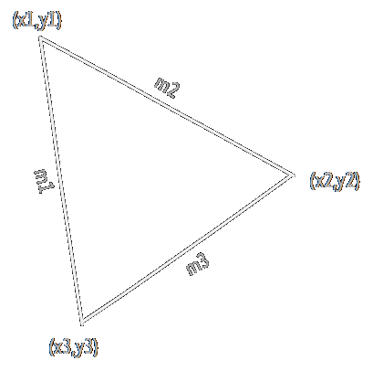
We start by sorting the vertices of the triangle top to bottom: (x1,y1), (x2,y2) and (x3,y3). We then calculate the gradients of the lines connecting the vertices, which we'll call m1, m2 and m3:
Next, we'll take to variables, xa and xb, which we'll use to walk along the edges of the triangle. Both will start at the top, at x1. xa will walk along the line from (x1,y1) to (x3,y3) using m1, and xb will walk along the line from (x1,y1) to (x2,y2) using m2.
Each scanline we just add the gradient value to xa and xb, and draw a line between them. When we reach reach y2, we switch to using m3 for xb, which now follows the line from (x2,y2) to (x3,y3). Draw a line for every scanline from y1 to y3 and we have our triangle. Of course, this way the triangle will only be filled with a single colour. The get some more variation, we can apply Gouraud Shading, which interpolates colour components from each vertex along the triangle. Again, we'll calculate a gradient for each edge:
We can then use variables ca and cb to calculate the colour at each point along the edges, like we did with xa and xb. Finally, we need to interpolate between the two edges on each scanline to get the colours in between, using another gradient:
We use the same calculation for each of the three colour components (red, green and blue), and for the z-coordinates (not really accurate, but close enough).
Now, we want to get all of this calculation to happen in hardware, so it's a good idea to summarise the operations we need to perform:
For each triangle:
- 3 divisions for each of x, z, r, g and b (15 in total)
- ... and a bunch of subtractions
For each scanline in that triangle:
- 1 division for each of z, r, g and b (4 in total)
- ... and a bunch of additions and subtractions
And for each pixel in that scanline:
- Just some additions!
Dividers in hardware are big and slow, taking up a lot of space on the FPGA, and taking dozens of cycles to get an answer. So, if at all possible, we want to avoid using them. And if we can't, we should take the time reuse them as much as possible. I'm happy to see that the operations we do most often, the per-pixel operations, are just some additions, which are really cheap in FPGA fabric. We can't really avoid the divisions in the per-triangle operations, but we really only need to execute that once per triangle. Compared to the number of pixels (hundreds of thousands per frame) the triangles are few in number (a couple thousand per frame), so we'll have plenty of time to calculate, and we could do it all with just one divider.
What I am worried about is the per-scanline operations. These will have to happen for every scanline, for every frame, so these could become a major bottleneck without a lot of additional buffering. Plus, I really want to avoid that second divider.
In the next post I'll perform some nasty mathematical hacking that makes Chris Hecker sad, and do away with that darned divider.
Discussions
Become a Hackaday.io Member
Create an account to leave a comment. Already have an account? Log In.