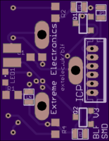
Close
0%
0%

BLF BOT (Black Line Follower)

A project to develop a small cheap black line follower Robot.

Similar projects worth following
There are many small robots and many brush bots, but they are difficult to build and use. There are very few small brush bots that will follow a line, probably due to the unpredictable nature of the bristles.

The BLF BOT is a single PCB that has a small processor two IR sensors and drivers for two small motors either vibration (or brushes) or geared (for wheels)

This project started as a fun project for a Scout group and then took over. Initially the goal was to make a simple, cheap and easily constructed project for the Scouts. Then reality happened. I realised that very few brush bots out there are autonomous, with hindsight I think that this is because of the irregularities created by using a brush and vibration motor combo. Inspired by the Kilobot project I continued.

The problem with the kilobot project is the robots aren't east to setup calibrate and use, they are much more capable than my design.

The kilobots use single pins in their design, my trials with these have been unimpressive, I've had much more success with brushes. I've tried many sorts of brushes from velvet to draught excluder, but tooth brushes work best for me.

The problem with any sort of brush, its its operation is pretty much random exactly not what you want from a robot drive system, although the software does try to allow for this it isn't perfect. The decision to go to a small uP control rather then a discrete control solution was taken very early on to give me some fiddle room / processing with the signals. This has allowed me to have a Shmitt like responce on the IR detectors and PWM for the motors and with the latest boards a calibration "learn" mode.

Although the main focus has been on a black line following brush robot, I would like to develop this into a small platform for any power train, motors, gears, wheels, lasers, Em drive etc.

  • 1 × 1uF 2.5mm Ceramic Cap
  • 1 × LIR2032 rechargeable 3.2V lithium button cell
  • 1 × 20mm Button battery holder vertical
  • 2 × QRE1114 (or QRE1113) IR proximity Detectors
  • 2 × 8mm Disk Vibration Motors

View all 14 components

  • BLF V3 board & motor / wheel test videos

    Extreme Electronics06/08/2016 at 18:38 0 comments

    BLF V3 boards test

    Motor test with V3 boards - Insulation wheels.

  • Motors and Wheels

    Extreme Electronics06/06/2016 at 22:27 0 comments

    Though id try the boards with real motors. The biggest issue was getting enough grip from the motors to the paper.

    My first try was Insulation from two wires

    Finally came up with a solution silicone baking sheet.

    Using a leather punch, you can cut out 3mm diameter disks, pus a pin through the middle and fit them to the motors.

    The problem now remains to control the power, PWM is giving me some control, but when there is only one motor running they don't have enough power. Awaiting a new SMT board from OSHPark, Hopefully this will cut down the weight

  • No Brush Brush bot

    Extreme Electronics06/02/2016 at 20:21 0 comments

    After looking at Steerable Bristle bot I saw a demo with no brushes and two vibration motors that were the same as I was using.

    After a few plays I got it working, but.. It only works on a flexible surface like rubber sheet or a mouse mat. Working on paper (even over a rubber mat) was very poor. This makes it difficult to add black lines, so Ive abandoned that method for now.

  • LIR2032 Coin Cell charger

    Extreme Electronics05/24/2016 at 18:34 0 comments

    Not really part of the project, but a needed accessory a charger for the batteries.

    Details at extelec.uk/bcc

  • BLF V3 SMT PCBs ordered

    Extreme Electronics05/24/2016 at 13:16 1 comment

    New SMT V3 boards ordered from OSH Park, Smaller, with pads for Learn Mode and an extra in only port for future development.

    plus and ICP header for programing the uP (needed as the chip is Surface mount and soldered in)

    Ill share in OSH park when the boards are proved.

  • PIC12F675 software

    Extreme Electronics05/24/2016 at 06:16 0 comments

    Code completed for the PIC12F675. I always viewed this as the processor of choice for the project, but I had PIC12F510 in stock so that came first.

    PIC12F510 has EEPROM on board. this makes the storing of calibration data possible.

    Due to the PCB design the only pin I could easily use without changing the PCB was the status LED, so bringing this pin high on power up now gives Learn mode.

    When used with the calibration track this will count transitions on left and right sides and adjust motor power accordingly to help maintain the bot in a straight line.

  • Inital working prototype

    Extreme Electronics05/22/2016 at 19:22 0 comments

    Working bot from the first PCB details added.

    More to come. PIC12F675 support - Calibration - SMD PCB - Geared motor tests.

View all 7 project logs

View all instructions

Enjoy this project?

Share

Discussions

cabalist wrote 05/27/2016 at 07:03 point

Some quick notes:

In the parts list:
LIR2023 should be LIR2032?


I am having a hard distinguishing/sourcing the following pieces.  Could you link to some examples?  
8pin DIP turned pin low level socket. (I don't know what 'turned pin low level' means)
8mm Disk Vibration Motors (I can find 10mm motors all over but no 8mm)


Small details and I have already ordered a number of things that I believe will work.  We will be building in a class setting so I want to make sure we get parts right.  :)

  Are you sure? yes | no

Extreme Electronics wrote 06/08/2016 at 18:32 point

Yes LIR2032 (typo corrected in the parts list) 10mm Vibration motors will be fine. I got my 8mm ones direct from China Via Ebay.  A low profile socket is simply a socket that is low to the board. Turned pin describes the small bucket sockets that the IC sits in. I use them because they survive multiple pulgging in/out better then the cheaper ones.

  Are you sure? yes | no

cabalist wrote 06/08/2016 at 18:38 point

Awesome.  Thanks for the clarification.

Somehow a google search turned up results this time that I missed last time.

Here is a turned pin socket for others:

https://imgur.com/5caakEZ

All the various parts are trickling in from China.  I'll update with any build notes we run into.  :)

  Are you sure? yes | no

Extreme Electronics wrote 05/24/2016 at 22:03 point

Yep, no one said it was going to be easy. Probably because I didn't ask. 

Its turned out to be way more difficult that I thought.

  Are you sure? yes | no

Mike Szczys wrote 05/24/2016 at 21:15 point

I love it! Oh the futility of mating these two types ofrobots (both favorites of mine) together.

  Are you sure? yes | no

Similar Projects

Does this project spark your interest?

Become a member to follow this project and never miss any updates