Close
0%
0%

Frostbite Detector and Alarm

A small pocketable or wearable device that can warn the user of prolonged exposure to cold conditions.

Similar projects worth following
This device is meant to reduce the number of injuries and deaths due to frostbite. The device is meant to notify the user that they have been exposed to cold temperatures for too long of a period of time. Frostbite can occur within 5 minutes, particularly at low temperatures.

According to the National Weather Service, Frostbite can occur in as quickly as 10 minutes at a windchill of -33 degrees Fahrenheit. In places with colder climates Frostbite can occur easily. (Sources: Business Insider: http://www.businessinsider.com/how-long-does-it-take-to-get-frostbite-or-hypothermia-2014-1 Modern Survival Blog: http://modernsurvivalblog.com/weather-preparedness/wind-chill-frostbite-chart/)

Chart representing windchill and time until frostbite occurs:


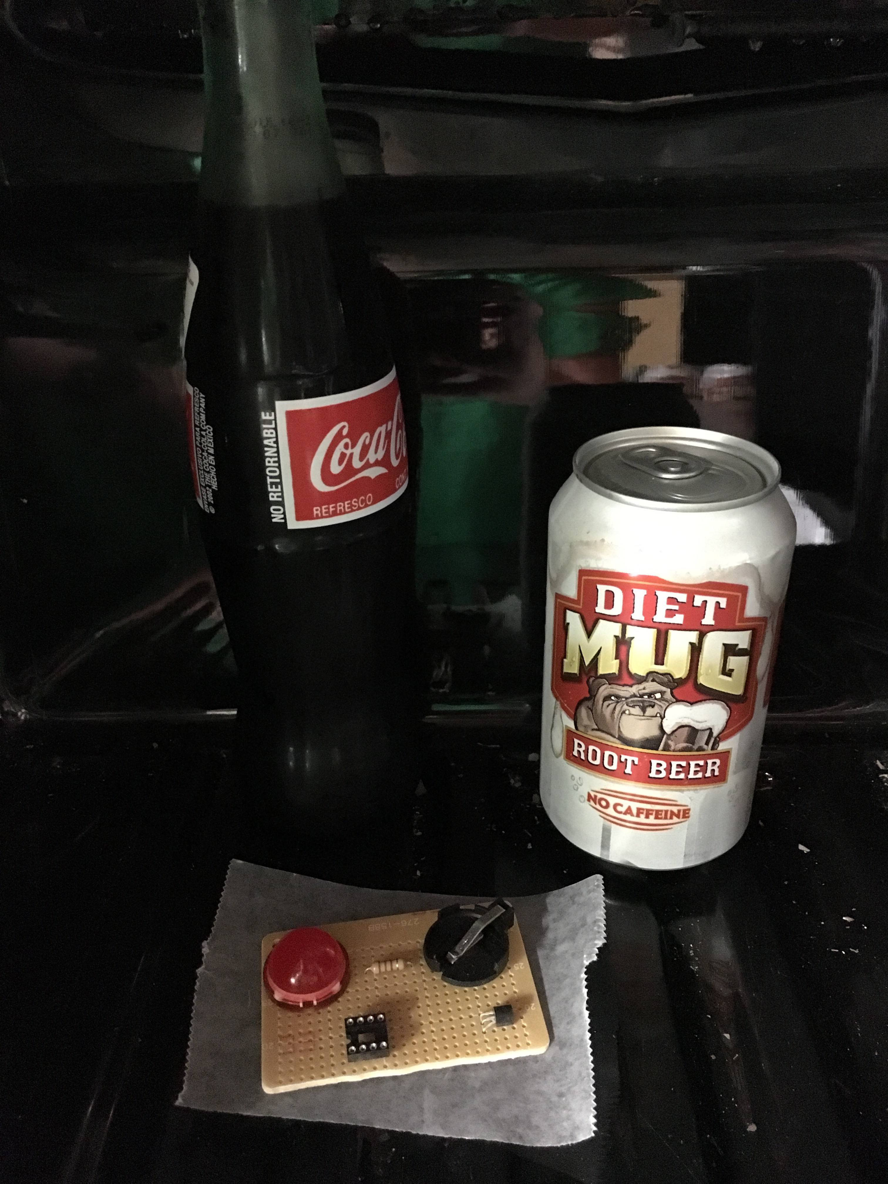
The device is small, pocketable, and battery powered, with future units possible featuring rechargeable lithium batteries. The device is meant to reduce rates of frostbite by notifying the user of conditions where frostbite is imminent with a solid LED, and when to take shelter with a flashing LED.


The device is meant for use amongst all ages, however can be specifically targeted at children to reduce or eliminate injury by cold weather afflictions like hypothermia or frostbite.


This project is licensed under the GNU General Public License.

Frostbite Alarm Bottom.stl

Bottom bumper for the PCB.

Standard Tesselated Geometry - 13.17 kB - 05/30/2016 at 02:48

Download

  • 1 × ATTINY85 Microprocessors, Microcontrollers, DSPs / ARM, RISC-Based Microcontrollers
  • 1 × Large 20mm LED A Large led that is available at RadioShack.
  • 1 × CR 2032 Batteries and Battery Accessories / Batteries.
  • 1 × CR 2032 Clip A battery holder for the CR 2032.
  • 1 × TMP 36 Temperature sensor.

View all 8 components

  • Testing

    Caleb Hanneman05/30/2016 at 00:44 0 comments

    To test the project, as it is summer at the time of this project creation, I have placed the PCB of the project on a place of wax paper and used a refrigerator to test the code and hardware. Along with the refrigerator, I have used a Peltier unit that is placed against the TMP 36. I have made sure of the temperatures with both the fridge and the Peltier unit using a Ryobi handheld, IR thermometer.

    Temperature from Inside the Fridge:

    • 45.2 Degrees Fahrenheit
    • 7.2 Degrees Celsius

    Temperature of Peltier Unit:

    • Varied based on voltage and current from a bench power supply.

    Picture of the PCB Chillin' in the Fridge (Pun Intended):

    The IC socket is bare in this photo, as it is purely a representation of the testing done on the project.

  • 3D Printing

    Caleb Hanneman05/30/2016 at 00:10 0 comments

    At this point I am 3D printing the enclosure of the project. The print is progressing well, yet I have had problems with warpage on the raft that I am printing onto, however this effects the actual enclosure very little, and where it does effect the enclosure, it is purely aesthetic damage.

    Printer Details:

    • Printrbot Simple Metal
    • No Heated Bed
    • Print Temp: 196 Celsius
    • Blue, Hatchbox PLA

  • Writing Code

    Caleb Hanneman05/29/2016 at 23:35 0 comments

    At this phase of the project I am writing the code that will run on the ATTINY. I am writing this in the Arduino suite, and programming the chip using an Arduino Uno in the "Arduino as ISP" configuration. You can find a guide on how to program ATTINYs with another Arduino at: http://highlowtech.org/?p=1695. The code can be found at the Github repo. Feel free to post errors within or criticisms of my sloppy code in the comments section.

  • Assembly

    Caleb Hanneman05/29/2016 at 22:49 0 comments

    In this phase of the project I am taking all of the components that were previously mentioned in the project, laying them out on a PCB, soldering them down and running hookup wire between them. I found that, much to my surprise, the pinout on the packaging of the 20mm led is totally wrong, and after a quick google search, I found the correct pinout. Thanks, RadioShack! (Sarcasm) When soldering down the TMP 36, a single inline pin IC, I bent the top of the chip down and taped the flat side of the IC to the PCB. I did this to keep things clean and to make soldering much, much easier.

    The finished IC is pictured here:

  • Case Design

    Caleb Hanneman05/29/2016 at 22:24 0 comments

    In this phase of the project I am designing an enclosure to 3D print for the project. The device is meant to be pocketable and a bare PCB does not fit the bill. The design work is being done in Autodesk Fusion 360. The measurements of the PCB are a follows:

    • The PCB is 2.8 in. by 1.9 in.
    • The tallest component that will be enveloped by the case is .5 in. tall.
    • The edges of the LED are .935 and 1.1 inches from the edge of the PCB.

    STL Files and CAD files can be found in the files section of the project.

View all 5 project logs

Enjoy this project?

Share

Discussions

Similar Projects

Does this project spark your interest?

Become a member to follow this project and never miss any updates