 Daniel Knezevic
Features
- Intervalometer: It is used for time-lapse photography. It controls how often, how long and how many shots are taken. If you set it to 2 seconds, for example, one exposure will be taken every 2 seconds until the Exposure Count limit has been reached (max 999 exposures).
- Bulb mode : It allows to take time exposures longer than 30s.
- Backlight
- Charging via USB
Introduction
TODO write me
Architecture
HW
- I built the project around a AVR microcontroller. I started the prototype with Atmega88 but 8kB of flash wasn't enough. To increase the flash size I chose Atmega328p. The mcu is clocked at 10MHz.
- The display is a PCD8544 84x48 pixel monochrome LCD display typically used in Nokia 5110/3310 phones. It can be powered from 3V3 and it draws very small amounts of power (around 200uA) making it extremely good for use in battery powered devices. The PCD8544 interfaces to microcontrollers through a serial bus interface (SPI).
- The LCD backlight is a custom made backlight with LEDs.
- As a user input 2 taktile type push buttons are connected to microcontroller. There are used internal pull-up resistors.
- A 3.5mm male jack connector is used as a camera output.
- A LiPo battery and a very low drop 3V3 voltage regulator (TPS79933) are used for powering the whole circuit.
- To measure the battery voltage a voltage divider and AVRs internal 1V1 voltage reference are used.
- To charge the battery a MAX1555 Li+ battery charger IC is used. It can be powered via USB.
SW
The software is written in C and compiled with avr-gcc.
The software is divided into 6 logical modules:
- TIMER
- BATTERY
- BACLIGHT
- GPIO
- LCD
- STATE
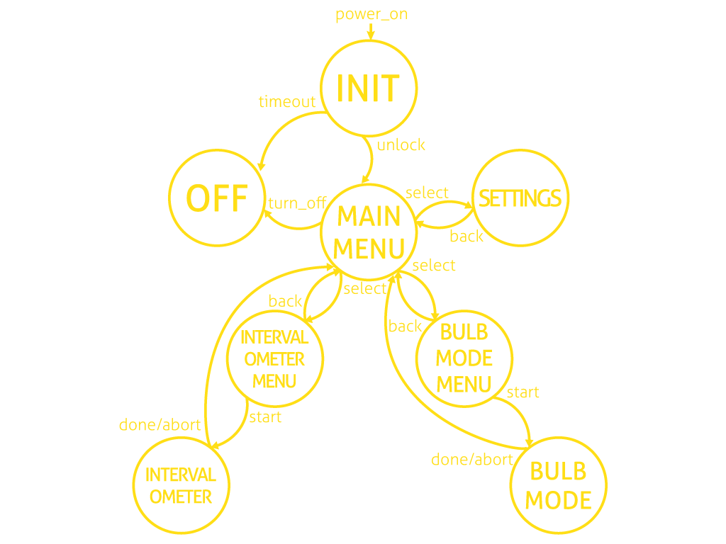
STATE:
State machine. The state machine is implemented by using function pointers.
Each menu state has three basic operations:
- show data on LCD
- wait for user input, update backlight and battery status
- handle button presses/holds
State machine diagram:
Initializes Timer1 and provides an interrupt based delay function.
BATTERY:
Initializes ADC to read the battery voltage.
Functions are used to control the backlight (initialize and update).
GPIO:
Initializes IO ports for:
- buttons
- camera output
- battery charger status indication
- auto cut off control output
LCD:
Most of the LCD related stuff is separated from the main source. This source code is independent from the main project. It represents the pcd8544 LCD driver, it is reusable code for other projects. The driver provides the API to initialize, control, and print text on the LCD.
The following project related functions are in the dintervalometer.c file:
- LCD_print_time - prints time in hh:mm:ss format
- LCD_update_scroll_bar - draws a scroll bar
- LCD_update_battery_icon - draws a battery tray icon
- LCD_show_low_battery_alert - shows a “Low battery” notification
Camera operation
Most DSLR and SLR cameras can be triggered remotely using a release cable. The standard solution consists of three wires: ground, focus and shutter. To focus the camera the focus wire has to be connected to the ground. To release the camera both wires have to be connected to the ground. Dintervalometer is tested with Canon EOS 700D. It has a jack plug for remote shutter. It's a DIY friendly stereo (3 pole) 2.5 mm jack plug.
Backlight Design
This backlight allows using the dintervalometer in the dark without an additional lamp. The backlight operates like a backlight of a cell phone: it is active for 10 seconds when the user presses a button or the dintervalometer finishes some job.
To increase the efficiency of backlight the LEDs are rotated 90 degrees. The top of the LEDs is on the side of the piece of transparent plastic. It was tricky to solder the LEDs on that way, but it is working well now :)
The following materials are needed for the backlight:
- sheet of white paper
- piece of transparent plastic
- double-sided tape
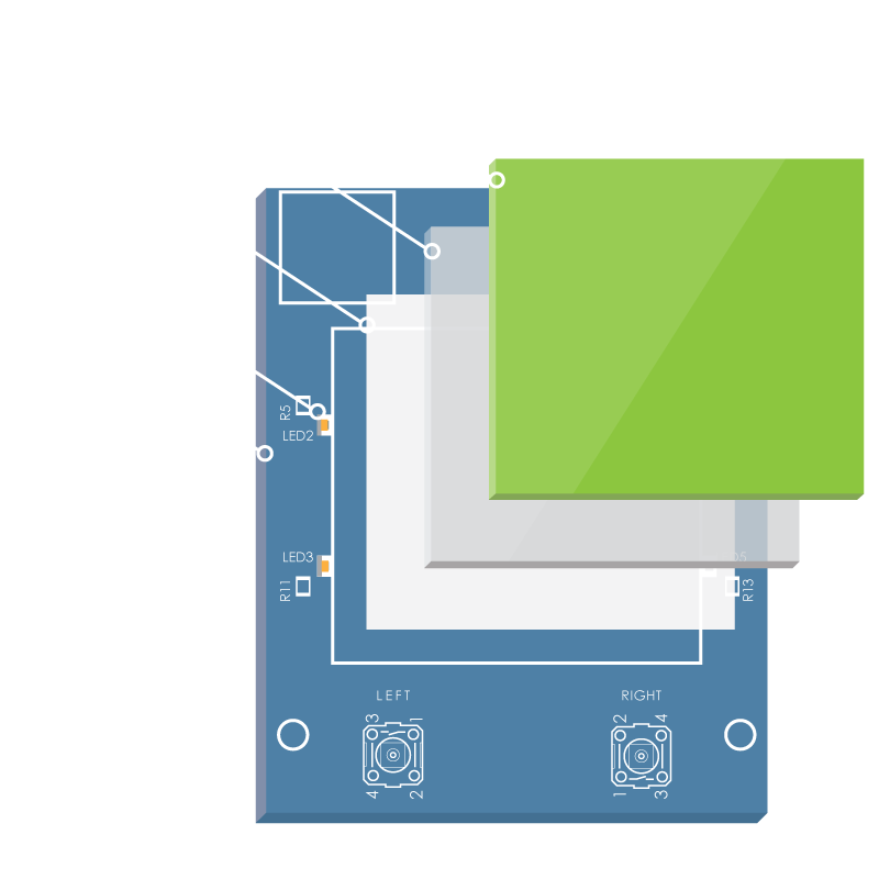 The first layer of the backlight is a sheet of white paper. The main function of it is to reflect the light of the LEDs. Then it comes the piece of transparent plastic. The top of the plastic is sanded with a fine sandpaper to diffuse the light. Finally, the LCD comes on the top. The layers are glued together with a double-sided tape.
Battery monitor design
LiPo/Li-ion batteries need special care in the way they are charged, discharged and stored. The battery must be monitored to prevent the over-discharge. In this solution the battery voltage is measured every 60 seconds. The user can always see the current status of the battery on the LCD. When the battery reaches the critical voltage the “Low battery” notification will be shown, then the device will turn off.
The typical LiPo or Li-ion battery voltages are 3V3 - 4V2. To measure the values with ADC a voltage divider is needed because Atmega328p has an internal 1V1 voltage reference.
The following equation is used to measure the battery voltage in mV:
 In this case the known values are R2=10k, R3=3k3, Vref=1100mV, ADCres=1024.
Schematic and PCB
On the picture below You can see the schematic of dintervalometer.
 Schematic and PCB are designed in Cadsoft EAGLE 7.2.0