 Ted Yapo
The tests I've done so far have indicated that there's something to be gained with pulsed LEDs for efficient glow markers, but the simple by-eye evaluation of relative brightness between the DC-driven and pulsed LEDs may not be very accurate. I've been playing with ideas to remove some of the bias from this comparison:
But I probably should explain how I got to this point first.
LED Brightness Spread
It's common practice for LED manufacturers to sort "identical" LEDs into bins based on brightness (if they're making this measurement with a constant current, they're really sorting by efficiency, but that's beside the point). Even if the two LEDs we are comparing (pulsed vs DC) are from the same brightness bin, there could still be some variation in brightness, perhaps skewing the comparison results. One solution would be to select a pair of LEDs for matched brightness from a larger sample of parts, but this presupposes an accurate method for comparing brightness. A simpler approximation is to test the LEDs twice - with each one in the DC and pulsed circuit in turn. If the difference in results between the two trials is too large, the LED pair can be rejected as "too different", and a new pair selected. If the difference is small, the average of the two trials could be used.
Light Detectors
Human Eye
The human eye can detect intensity differences of about 1% (see Poynton's Gamma FAQ, Section 13). It sounds good enough, but this is based on comparing two homogeneous light patches right next to each other. With LEDs and their varying radiation pattern, I seriously doubt you can approach this accuracy looking directly at them. I had some early success placing a sheet of paper over two LEDs to diffuse the outputs - what I had made was a primitive Joly photometer. I decided to take this one step further and construct a 3D printed version especially for use with LEDs. The design uses a thin separator, 1 extrusion width thick, to divide two compartments filled with paraffin wax:
I printed one, but failed at the first wax casting:
Even with this lousy construction, it was clear that this approach is flawed for low light levels: too much light is lost due to scattering and absorption in the wax. The LEDs here are running at about 10mA, and are plainly visible, but at very low currents, it's simply not workable. I think with greater care casting the wax, this approach could probably be used for brightness comparisons at relatively large currents, but it's not much use for designing glow markers.
Another reason not to use the human eye as a detector is psychological bias. I'd like to show that this pulsed-LED idea works, and I fear that I might subconsciously skew the results.
Electronic Light Sensors
I have been playing with the VEML7700 ambient light sensor from Vishay. While the VEML700 has good sensitivity, wide dynamic range and a spectral sensitivity curve very closely matched to the human visual system (photopic vision only, unfortunately), coupling LEDs to the sensor repeatably is problematic. Because of the angular dependence of the LED output, and to a lesser extent that of the sensor, the coupling coefficient is sensitive to misalignment - obtaining the same coupling between two LEDs and their respective detectors isn't easy. The usual way to make such measurements angle-independent is to use an integrating sphere, which solves the problem by forcing many "random" Lambertian reflections between the emitter and detector. Builds for spheres abound on the Internet, and a very good reflective coating can be made cheaply with flat latex paint and barium sulfate, but the light "loss" due to the number of internal bounces and the small fraction of light directed to the detector also render this method impractical for low-output sources.
I'll note that for relative intensity or efficiency testing with a single LED, repeatable coupling isn't required as long as the coupling doesn't change over the course of the measurements.
The other possible factor affecting electronic sensors is the high-speed pulses generated by the glow marker circuits. It's not clear yet if the VEML7700 integrates such pulses accurately, and the maximum 800ms integration time would require averaging multiple samples to obtain good accuracy with approximately 50 Hz pulses. Even returning to previous designs I've used, it's quickly apparent that the simple photodiode + transimpedance amplifier circuit often used for "DC" light measurements requires some very careful design to accurately measure pulsed sources like this.
Cameras
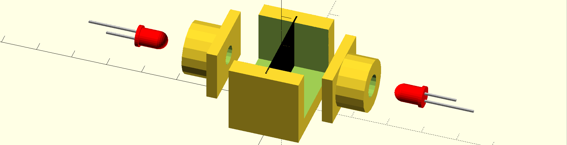
Off-the-shelf DSLR cameras seem like a very good sensor for comparing dimly-lit LEDs. They are quite sensitive, handle long exposure times for integrating pulsed light sources accurately, and are easily calibrated with a series of "dark" and "flat" exposures (more on this later). I decided to go back to my first paper-over-LED comparator idea using a DSLR as the sensor. I designed a comparator cell for 3D printing:
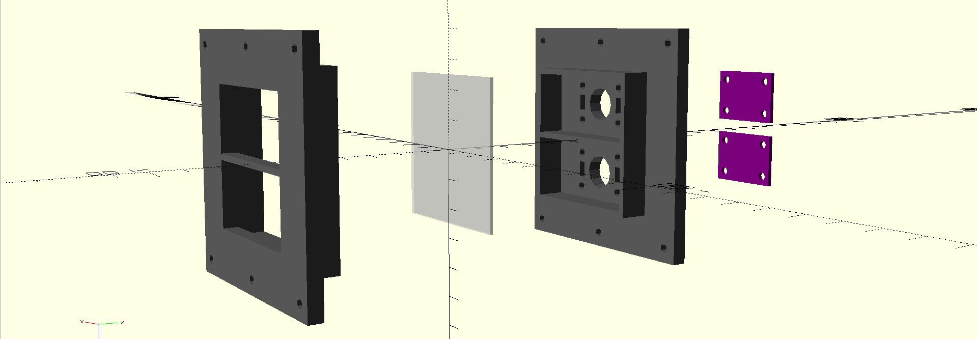
The cell is designed to mount on a MakerBeam frame. The two LEDs to be compared "project" their light onto a 50mm square ground glass screen. The exact fraction of light captured by this method is not important, as long as the two LEDs generate similar patterns (this setup is designed for two "identical" LEDs, not to compare different types). Two LED carrier boards are attached to the rear of the cell. Here's the design for LEDs in 5mm T1-3/4 packages:
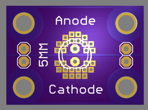
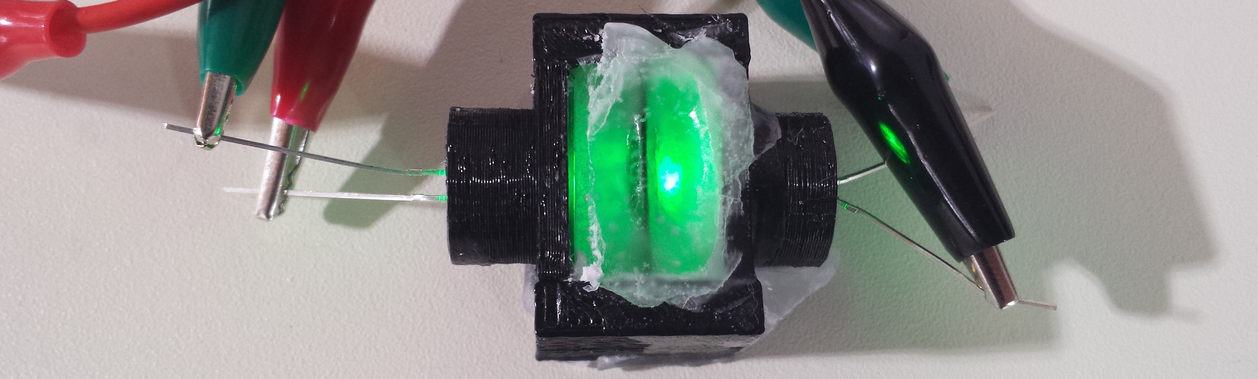
I've designed a number of such boards to carry the LEDs in various packages I intend to test (more on this later). Instead of waiting for the boards to come back from the fab, I printed some "fake" boards to hold 5mm LEDs for testing:
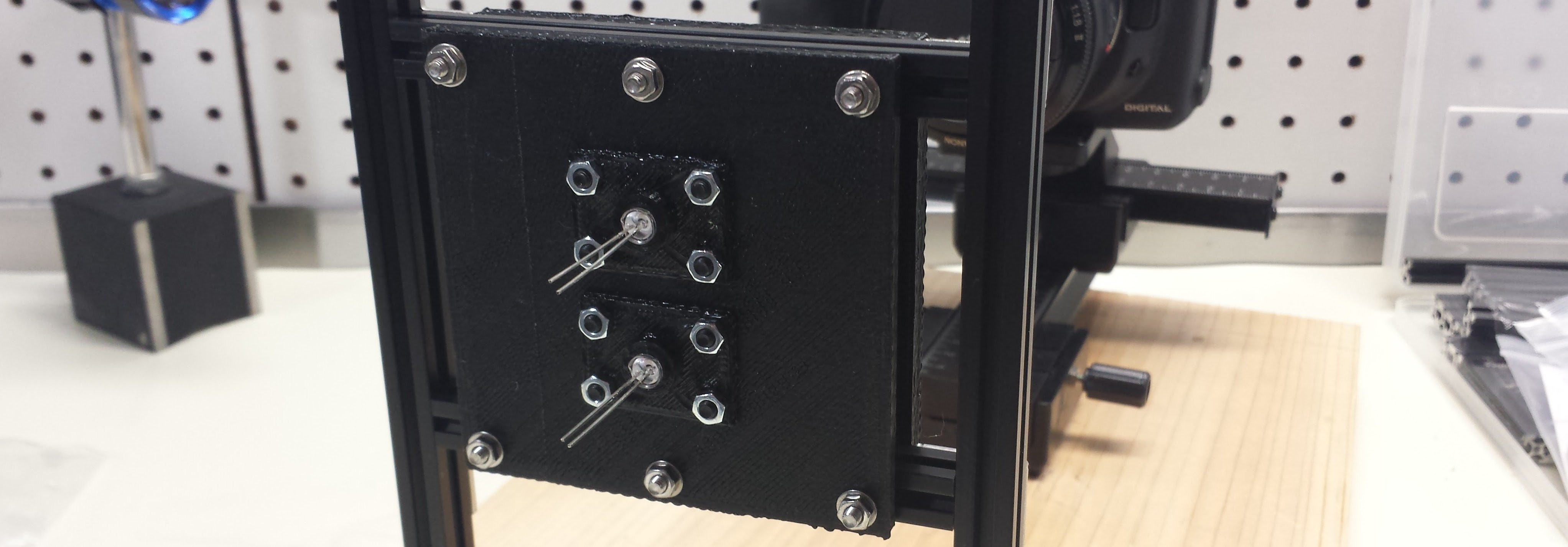
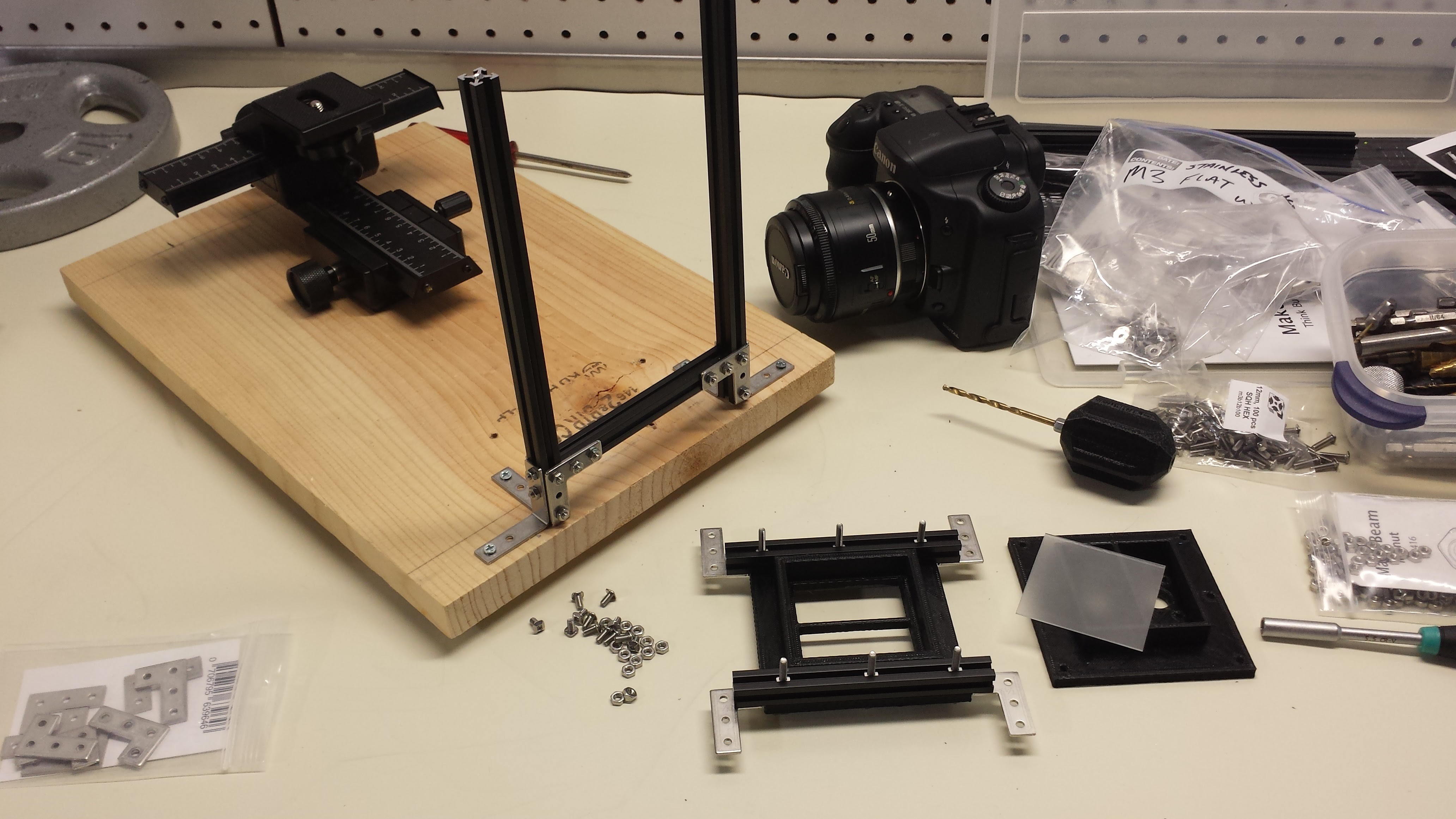
Here's what the whole assembly looks like:
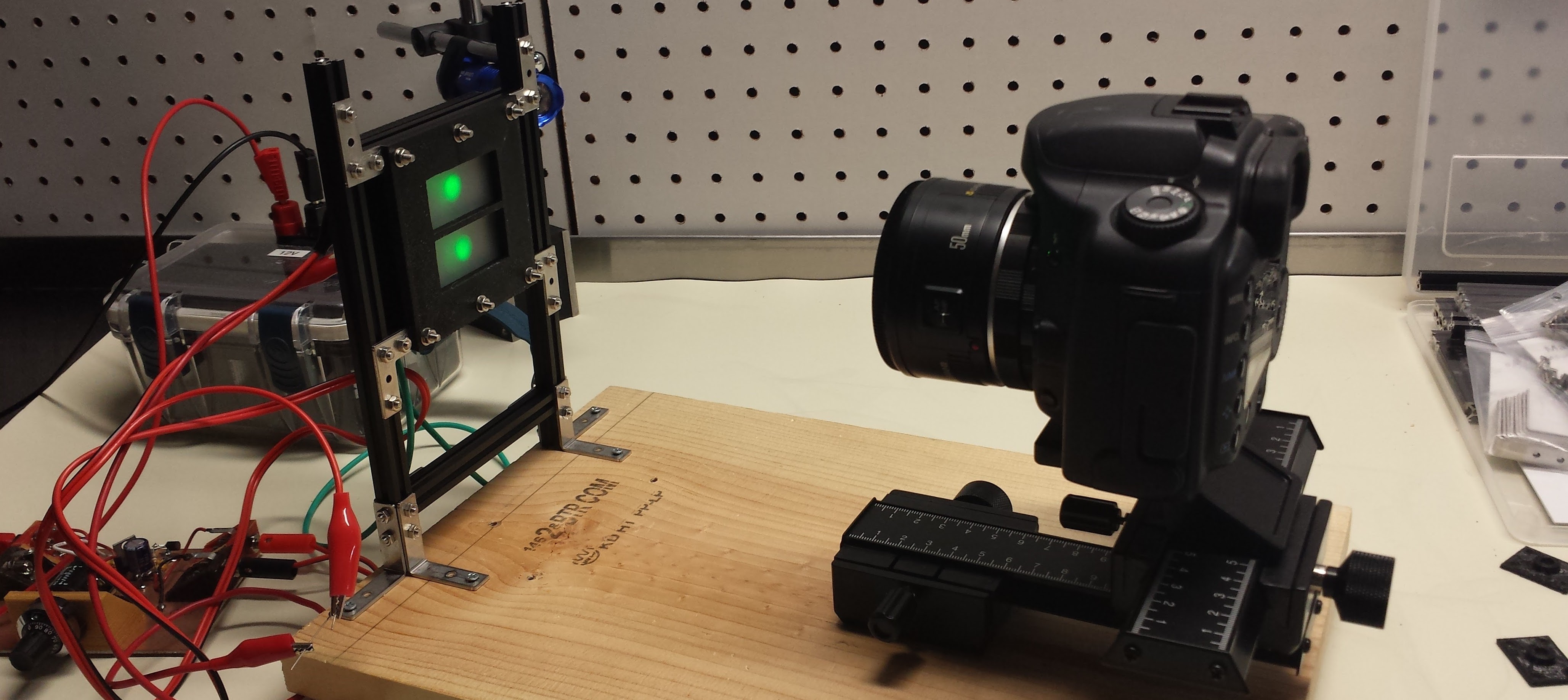
A Canon EOS-10D is fitted with a 50mm f/1.8 lens and a macro spacer ring to allow it to focus on the close screen. The LEDs are cranked up very bright for this photograph - in practice, they are much dimmer, and the whole assembly is covered with a cardboard box to block ambient light. The camera can be operated remotely over USB (1.1 ! - it's an old DSLR).
Here's a sample image captured with the setup:
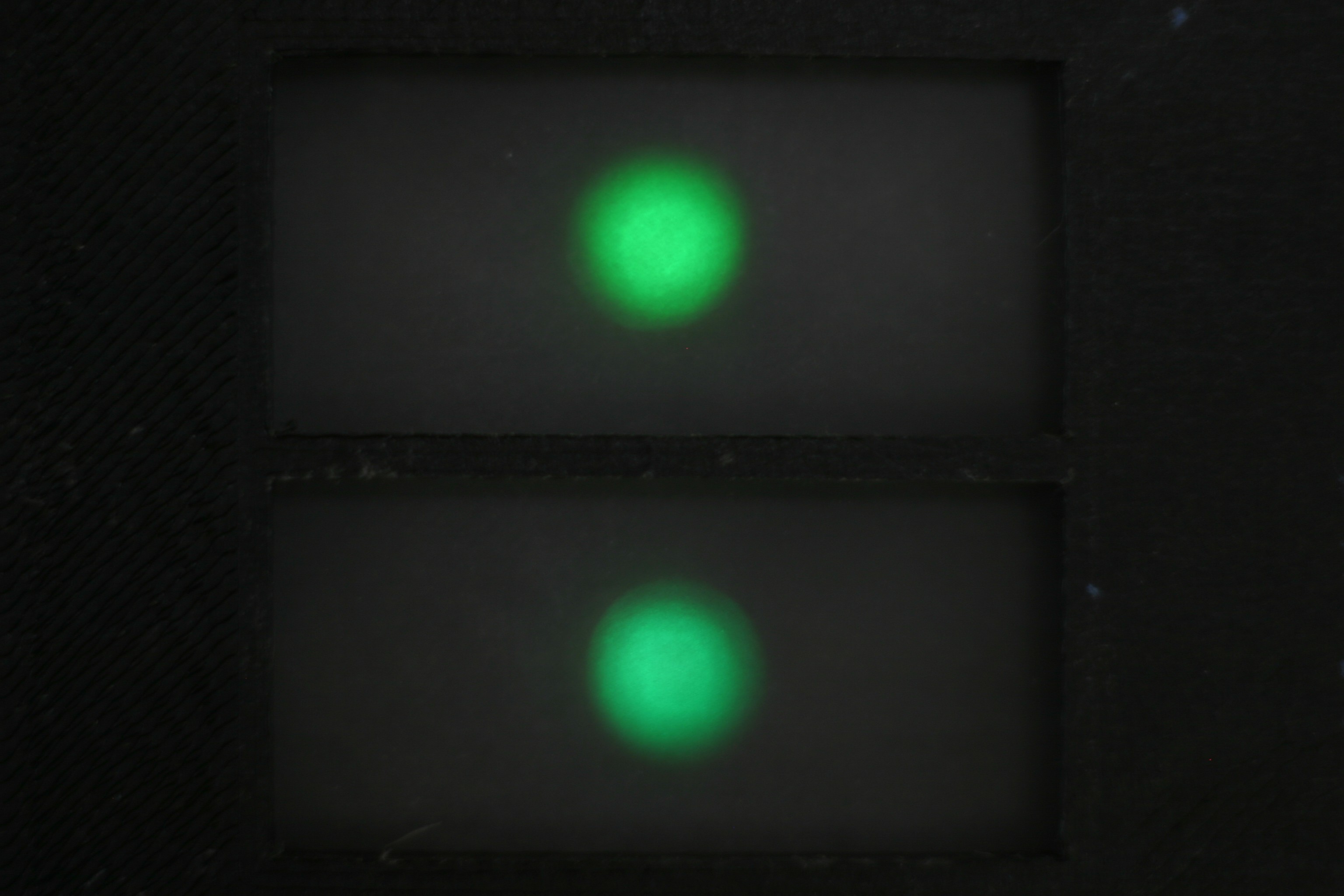
This image was taken in normal room lighting (no cardboard box), and the LEDs were roughly held in place with tape, but you can get the idea. The EOS-10D has a 12-bit ADC, and the linear Bayer-pattern output can be obtained from images taken in "raw" mode then decoded with the excellent open-source dcraw utility. I've done this before for scientific applications, and it works very well. I have yet to write the comparison code, but it should be straightforward: mask off two image areas corresponding to the two LED windows, then sum up all pixel values in each window and compare the results. Any images with saturated pixels (4095 counts) need to be rejected, since this clipping will affect the results.
To get accurate data from the camera sensor, it first has to be calibrated. This problem has been well studied for astophotography, and calibration using dark and flat frames is the norm. A dark frame is one taken with the lens cap on - this reveals the dark-current in the sensor, "stuck" pixels, and amplifier glow, which can be subtracted from the LED images. A "flat" frame is used to calibrate the camera for vignetting of the lens system: image brightness tends to fall off away from the center of the image. To capture a flat frame, a uniform intensity surface is photographed. I ordered one of these LED backlights from Adafruit:
 Of course, I don't know how uniform the output from the backlight is, but I can try it in several orientations and positions to see how similar the generated flat fields are. I also found a 10cm square EL panel on ebay to try. Between the two, and possibly a few more sheets of ground glass, I'm confident I can generate decent flats.
LED Test Boards
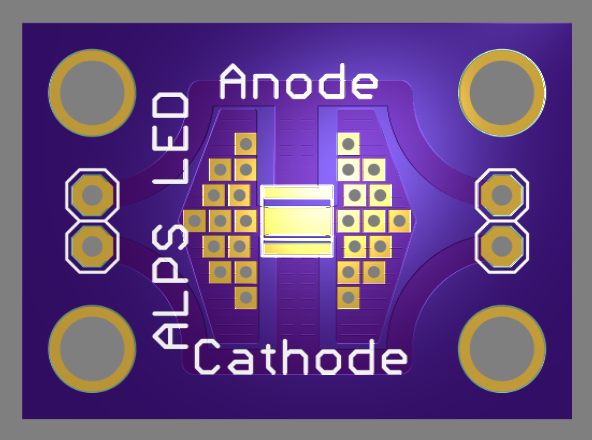
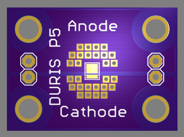
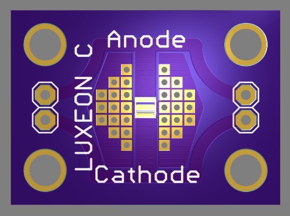
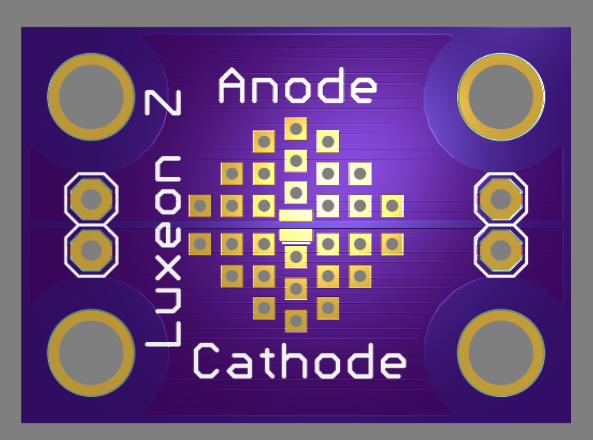
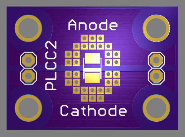
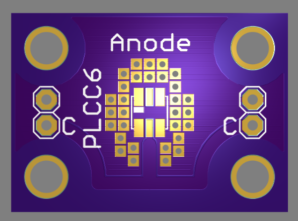
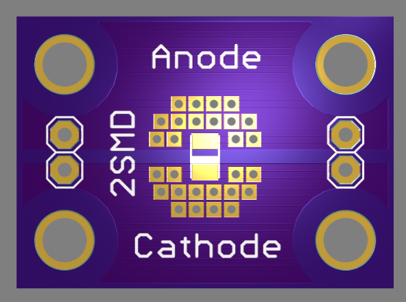
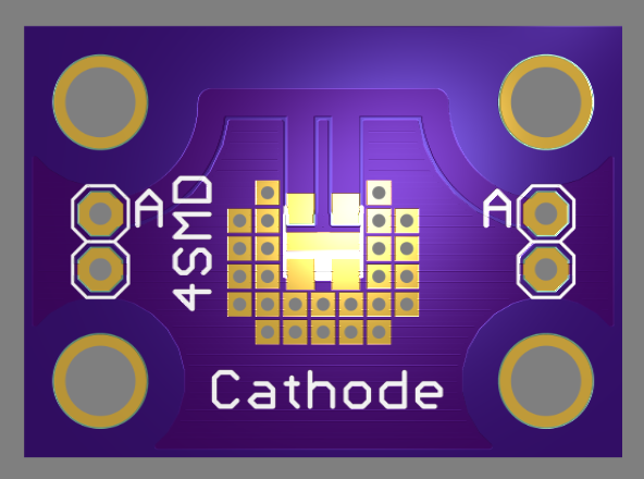
I designed 10 boards to test at least 11 different LEDs (some boards will accommodate several different model LEDs). Here are the other 9 designs, along with the target LEDs (and links to datasheets):
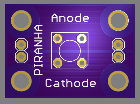 Piranha / Super-Flux
 Würth 150141GS73100
SunLED XZM2DG45S
Next Steps
I have to wait for a lot of boards. My batch of #Ugly SMD Adapters for prototyping the next versions of the pulse circuits were lost by the USPS. OSH Park is rushing a new order for me, but it will still be a little while. The 10 LED carrier boards will take a while, too. In the interim, I can write some software for comparing LEDs and get some mileage testing 5mm parts.
Discussions
Become a Hackaday.io Member
Create an account to leave a comment. Already have an account? Log In.
Do you still have the files for the test boards? I was going to create one for the Luxeon C led's but you've already done the work.
Are you sure? yes | no