 Ted Yapo
I have long considered trying to remove the microprocessor from the design, and decided to take a few minutes to test out some ideas. I had the parts for this experiment sitting in a box for over a year...
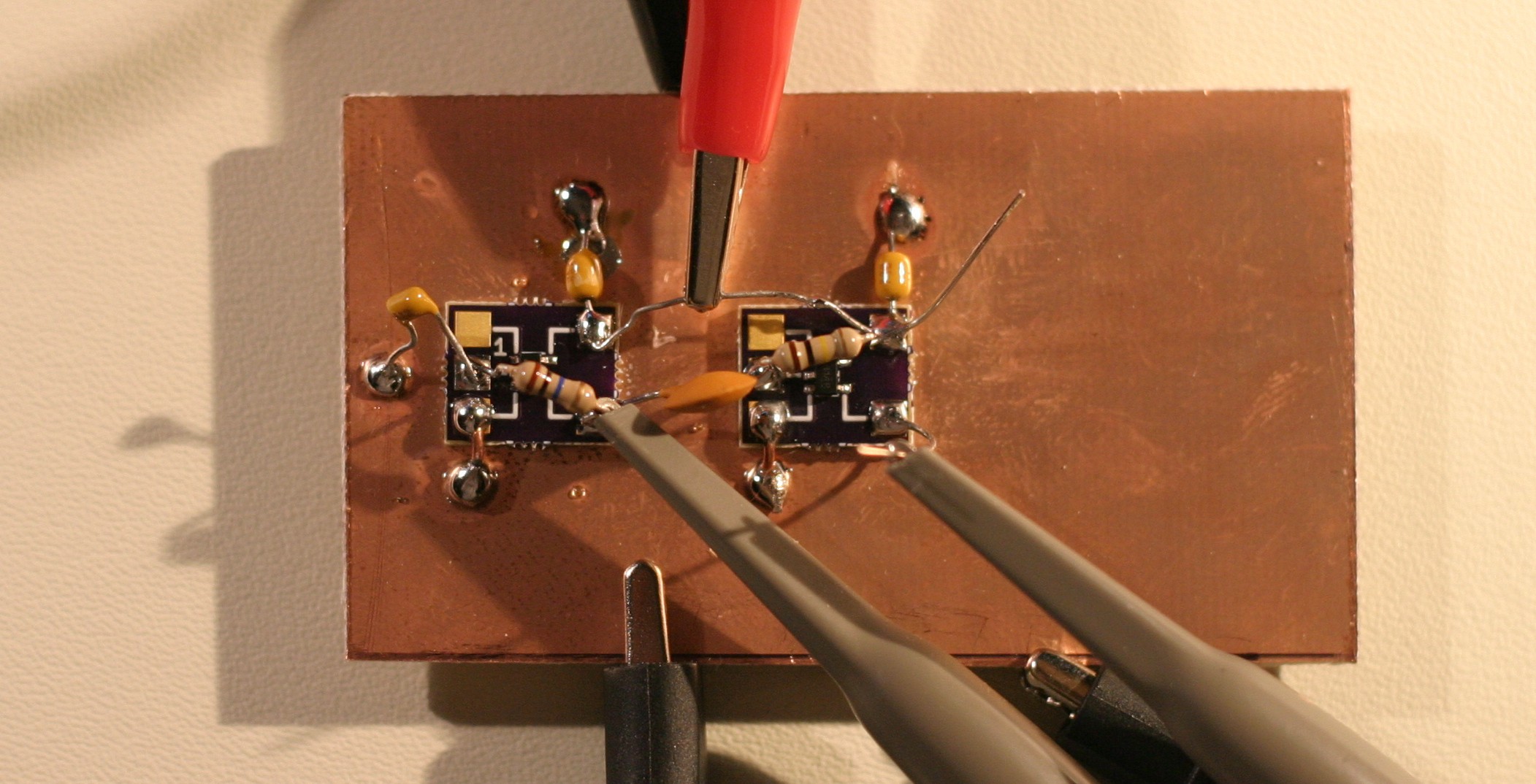
The board has two 74AUP14 Schmitt-trigger inverters in SOT23-5 packages mounted on #Ugly SMD Adapters glued to the ground plane. The first inverter is used as a relaxation oscillator, while the second is used after a differentiator as a short pulse shaper:
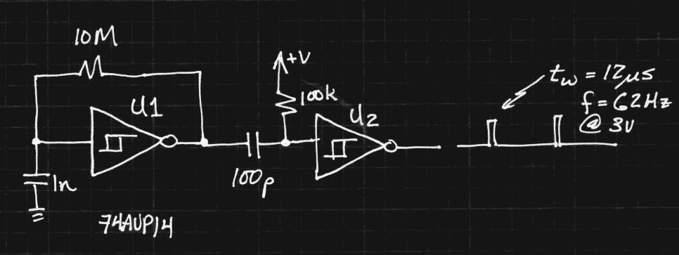
The 1n capacitor has a terrible tempco, so every time I read it, I get slightly different frequencies - especially if I had recently soldered the board, or touched the cap. The output of the first inverter is a nice square wave at around 65Hz (yellow trace):
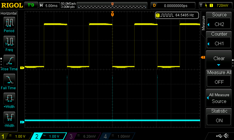
Zooming the time scale, we see the output of the second inverter (cyan trace) is a clean 12us pulse on the falling edge of the square wave:

With a little tweaking, this would be a perfect waveform to drive the MOSFET/inductor boost circuit. Except for one thing: the circuit consumes 160 uA! This is without driving an LED, and is already an order of magnitude more than the "standard" TritiLED program running on a PIC. Craziness!
The problem is that the inverters (74AUP1G14's) consume a lot of power when biased into the linear region, which the relaxation oscillator is always in (the culprit being shoot-through current between the high- and low-side MOSFETs). I was really surprised by this result because the 74AUP is advertised as the "lowest power" family, and the datasheet specifies 0.5uA quiescent drain maximum at 25C. With the feedback connection on the first gate broken, I actually can't detect *any* current used by the circuit with my DMM, which has 100nA resolution.
The pulse shaper seems to consume a negligible amount of current by itself: now I'm wondering how to make a really low-power oscillator.
For the time being, I'll stick with using a PIC15LF1571, but it's still fun to consider simpler options.
Ideas?
UPDATE 20170710
I tested the current drain on the first inverter. I removed the 10M resistor, and briefly charged the 1n capacitor by connecting it to the 3V supply. The capacitor takes about 30 seconds to discharge due to a combination of internal leakage and input current into the inverter. When the capacitor is charged to 3V, or fully discharged at 0V, I read zero quiescent current for the inverter (again, the meter resolution is 100 nA, so I assume the current is less than 50 nA). During the 30 seconds while the capacitor discharges, the current draw increases to a maximum of 220 uA, then falls back down to "zero".
This is why they tell you to ensure than all unused CMOS inputs are tied to either Vss or Vdd. Being in-between can cause some hefty current drains.
SECOND UPDATE 20170710
@AlliedEnvy lent me a clue in the comments - reduce the supply voltage. The circuit oscillates with supply voltages down to 0.25V (at the temperature in my office, anyway), and seems pretty stable above 0.4V. Interestingly, the power consumption drops off dramatically with supply voltage. At 0.95V, it draws 1.0uA, while below 0.75V, the current drops below the 100nA threshold on this DMM. I'll have to drag out the good HP meter to investigate more closely.
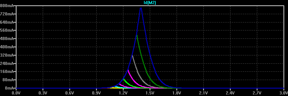
So, the shoot-through current in the middle of the input range is a strong function of supply voltage. To investigate this, I made this quick model in LTspice, using the N- and P- parts of and FDS9934 to make an inverter. I just chose those because it was the first complementary pair I found in the library:
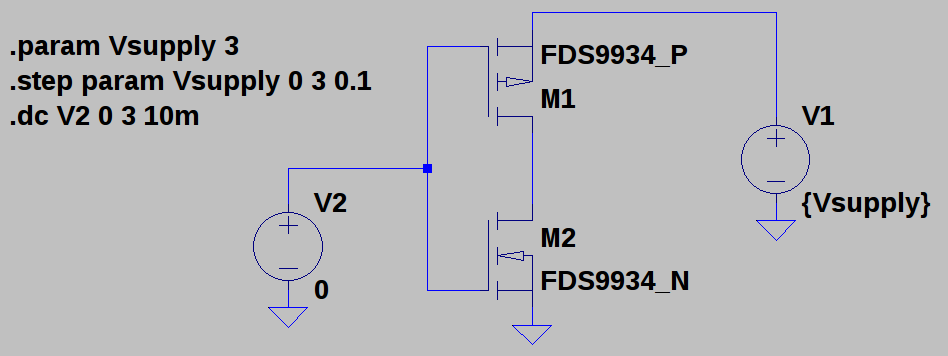
You can see how the shoot-through current gets reduced here. The top (blue) curve shows the current drawn from a 3V supply as the input voltage is swept from 0 to 3V - it peaks near 1.4V at 800 mA for these particular MOSFETS. The other color curves show the same thing for lower supply voltages stepped in 100 mV increments. By 2.3V, the maximum current is below 10mA. By 1.8V, it drops below 10 uA.
Although there are still issues to be worked out, this may not end up being such a fail after all. Thanks for the helpful comments, everyone! Keep 'em coming - I need all the help I can get :-)
Discussions
Become a Hackaday.io Member
Create an account to leave a comment. Already have an account? Log In.
Rather than a Schmitt Trigger, a proper comparator will not have such excessive current usage. Take the MCP654x set from Microchip: http://ww1.microchip.com/downloads/en/DeviceDoc/21696H.pdf Figures 2-15 and 2-18 on page 8 show the supply current plotted against the input voltage, and it stays under 600 nA across the full range.
A few passives (4 resistors and a capacitor) should be able to turn it into an oscillator. I went through the trouble of working it out myself, and found out that I had reinvented this circuit:
Sufficiently high values for the passives can keep your supply current down, but it also becomes more sensitive to leakages and external noise. I don't know how big of a deal that would be, since this isn't a precision circuit.
Are you sure? yes | no
Yes, that's a good point. There seem to be a number of nano-power comparators on the market which might work as the oscillator stage.
Now, I need something better for the pulse shaper to create relatively stable pulses of 1us or less in order to be able to use smaller inductors. Unfortunately, the nano-power comparators seem relatively slow - I can find 2us delays, but not much less. Th Schmitt trigger inverters are much faster, and aren't power hogs in that stage, but the poorly specified hysteresis would allow for a large tolerance on the pulse width, and hence the LED current.
Are you sure? yes | no
For the pulse shaper, how about a (non-Schmitt) buffer with a feedback resistor to create the hysteresis? Might have better tolerance.
And if that works, it might end up cheaper to use a 2+-input part (and, or, xor, xnor) and tie the unused inputs to the relevant rails.
Are you sure? yes | no
@AlliedEnvy That's a possibility. I'm also wondering how closely matched the thresholds of multi-gate packages are - at least they will be at the same temperature. I think you could use a pair of gates to partially compensate for the threshold tolerance, as long as they're relatively matched. For instance, use two RC's, one with a longer time constant, to drive gates, then combine the resulting pulse with a 2-input gate. The resulting pulse has less dependence on the exact threshold.
Are you sure? yes | no
@Ted Yapo It sounds like you're trying to reinvent a rising edge detector.
Instead of an inverter chain, you could use a single Schmitt Trigger with an RC filter on the input to tune the delay and adjust the pulse width.
Are you sure? yes | no
@MarkRD yes, exactly - I've used rising edge detectors like that, except with an RC delay in there, the delay you get is not only a function of RC but also of the threshold. I can get 1% R's and C's, but the threshold on logic gates varies widely. You can substitute a comparitor for the gate after the RC for more precision, but fast nano-power comparitors don't seem to exist.
The thought was to use two legs with RC's so that you could compensate for the wide tolerance on the logic threshold - assuming that the threshold is similar for inverters on the same die.
Are you sure? yes | no
This spec is in the datasheet. It's in the Electrical Characteristics table and labeled ΔIcc. You're measuring significant;y higher than the quoted spec though, maybe you've got some extra leakages in there that are hosing your current usage.
For your reading pleasure, I found an application note from TI called Understanding Schmitt Triggers: http://www.ti.com/lit/an/scea046/scea046.pdf
Given that this ΔIcc thing appears to be a common feature of Schmitt Triggers, I don't think there's much promise in this.
Are you sure? yes | no
Thanks, I didn't know what the ΔIcc parameter was!
I see it in the datasheet specified as 40uA max (at 25C), but the conditions are with a 3.3V supply and the input at Vcc - 0.6 = 2.7V. I think I'm seeing that the current is higher with the input closer to half the supply voltage - which would still meet the datasheet spec. if I weren't a few hours past bedtime, I'd measure it now. Maybe in the morning - well, later morning.
But, with a reduced supply, this current can be made very low. These parts are spec'd to run down to 0.8V - at around that voltage, I see sub-uA currents for the oscillator. It actually seems pretty good.
Are you sure? yes | no
I'm rather surprised that this issue is so obscure. I didn't know what that parameter was either until I found the TI app note. It's quite a major weakness using Schmitt Triggers in low power applications.
The major downside to reducing the voltage to the Schmitt Trigger is that it weakens the output drive capability. Which MOSFET are you using? Driving the gate with such low voltage might have too much RDS, wasting some of the power that should have gone into the inductor.
A thought I had is to clock a PIC timer with a 32 kHz watch crystal and use a PWM peripheral with very low duty cycle to generate gate pulse. That way the microcontroller can stay totally asleep except during initialization. I know the ATmega328P uses about 1 uA typical in that mode, but its timer is only 8-bit. Not enough for the small duty cycles you're shooting for. I'm having trouble finding a small PIC with a comparable feature.
Are you sure? yes | no
Checkout page 14, figure 14
https://assets.nexperia.com/documents/data-sheet/74AUP1G14.pdf
Unhelpfully truncated, but I came across this while ordering some of these to test in some other circuits.
Are you sure? yes | no
@Michael Stoiko yeah, that datasheet has the right info! Nice to see suspicions validated.
@MarkRD The major offender in this circuit is the oscillator - the pulse shaper doesn't draw that much current even at 3V, because it mostly stays out of the linear region. So, the idea would be to run the oscillator at a lower supply, then the pulse shaper at the battery voltage. There's an example of this in the Art of Electronics V3, where they made a 32kHz watch crystal oscillator with these same gates. The oscillator gate has 10k resistors in the power and ground connections to "float" it around the center of the supply voltage, while reducing the supply it sees. A second inverter stage can boost the output back to the rails.
I could imagine doing the same thing here. The Rds isn't too much of an issue with the circuit as it is - the inductor has 5 ohms of resistance anyway, which dwarfs decent MOSFETs (even weakly driven ones).
Newer PICs have ultra-low power 32kHz oscillators built-in. You can't keep time with them, but that's OK in this case. I looked around for a PWM solution, too, but didn't find one.
I'm still liking a separate oscillator/pulse shaper architecture. The oscillator could just be a PIC, something made from CMOS gates or discretes, or one of the nano-power oscillator ICs. The pulse shaper needs a little more thought, maybe a nano-power comparator, although I think they're all too slow.
Are you sure? yes | no
IANAEE, just a well-read software guy, so take this with a grain of salt.
I was looking into low-power oscillator designs awhile ago, and thought about this same circuit with this same AUP Schmitt inverter part. I did think the shoot-through current was going to be a problem.
I was considering a comparator wired up in a Schmitt inverting configuration, but I decided power wasn't all that important in my case and ended on a CMOS 555. Still haven't finished the design for that project.
Maybe even a quartz oscillator with a frequency divider would work. You probably don't need the accuracy or stability, but if they use them in wristwatches that last years on a battery, I wouldn't expect them to use much power.
Hmm. Flipping through chapter 7 (oscillators and timers) of AoE, 3rd ed; fig 7.40 on page 448 looks relevant. They're using the same AUP logic family, too, but for a Pierce oscillator for a wristwatch.
I don't fully understand how it works, so I can't describe it accurately; it looks like their trick is running the oscillator from a low voltage, with 10k resistors on the inverter power rails (to reduce current?), and then boosting the low-voltage signal back to useful levels with an additional stage. They report 2.4 uA from 1.0 and 1.8 V supplies. If you don't have a copy, I'll be glad to send a pic of the page in question.
Would the final stage would even be necessary here, if you have a low-enough gate threshold on the drive transistor?
Oh, and if you're going to be using more than one inverter, they make em with 2 or 3 in a single package.
Are you sure? yes | no
Thanks for the pointer to AoEv3. I have a copy, and will check that out - I skimmed that section a while ago for something else.
And, thanks for the clue about the supply voltage! I'm not sure how this will work over temperature, but the initial tests look promising. I just tried reducing the supply voltage - either with a variable supply or a series resistor in the power lead. At 1.8V, the circuit only draws around 42 uA - so 1/4 of what it was. It will actually continue to oscillate (crudely) down to 0.25V, and looks "normal" at around 0.4V. Neither one registers any current on my meter - I have to raise the supply to 0.76V before I get a consistent 0.1uA reading - and the current stays below 1 uA until a supply voltage of 0.95V. This is very interesting, especially since the output stage works, too - yes, it could probably just drive a low-threshold MOSFET as-is.
Two issues remain - first, the varying supply voltage changes the hysteresis levels on the input, so the frequency changes with voltage. At 0.95V, the frequency has increased to 93Hz. Maybe you could use this to maintain brightness (by issuing more pulses) as the battery voltage drains.
The other issue is efficiently deriving a stable supply somewhere between 0.75 and 0.95 from the battery voltage of between 2 and 3V (or 3.6 for LiFeS2 cells). You'd need some kind of nA-quiescent-current LDO regulator. I don't think a resistor is going to work well over that input voltage range.
Still, this is a very interesting direction.
I've seen the multi-gate packages - that would be my preference with finished designs - but for prototypes like this, single-gates are awesome mounted on individual SMD adapters. There's plenty of room to use through-hole passives, which are easy to work with and I have way too many of :)
Are you sure? yes | no
Hmm. For the supply, how about using a forward-biased diode, sort of backwards to using a Zener, as a voltage regulator.
Are you sure? yes | no
A forward-biased diode might work, but you'd typically run a shunt regulator at several times (at least) the load current for stability, which would be expensive in this case. Also, the forward voltage of common diodes is pretty low at tiny currents - see the 1N4148 here:
at 1uA, it only develops 300mV. So to get a 0.9V regulator that only consumes 1uA, you need 3 diodes in series. So, now you have a 0.9V regulator that eats 1 uA quiescent, and may be good for a few hundred nA load current. Seems expensive for a regulator, but the whole thing may still be under the power budget.
I'm also not sure what the temperature coefficient does at these low currents.
It's a cheap solution, though, and maybe you could get it to work.
Are you sure? yes | no
I mean, there are other, even more exotic chips to try. LTC's nanowatt comparators seem promising, but list specs similar to the 74xx14 you used.
http://www.linear.com/product/LTC1540
This little guy looks intriguing, too.
https://www.sitime.com/products/datasheets/sit1534/SiT1534-datasheet.pdf
Are you sure? yes | no
Thanks for the links!
I looked at LTC's comparators for this before - I can't remember if I ended up buying a few - I'll have to search through the boxes. I think I decided against them for some reason, which I should have written down...
I hadn't seen the SiT1534 before - that looks really interesting. Digikey stocks versions programmed for 32 and 64 Hz, perfect. The downside is that they are in crazy tiny packages and cost more than the PIC.
I'm measuring the PIC overhead at around 3uA in some cases, the SiT1534 might cut that in half. On the other hand, you need maybe 10 uA minimum to drive the LED to decent brightness, so the percent savings you get is maybe 10%.
Worth playing with, anyway.
Are you sure? yes | no
I've still had zero workshop time to play with this, but I'm wondering if a relaxation oscillator based around one of these old solarengine circuits could work. I say that only because the "tiny photopopper" circuit that launched me on this whole project was claimed to be operating off a panel that was outputting 1 ua.
https://www.fetchmodus.org/projects/beam/photopopper/
That one. I haven't been able to find an ISL88001 in the range this person used, but I have a couple in various voltage ranges. It would have the problem of varying frequency with voltage pretty heavily as the battery discharges, but if the voltage detector is only consuming nanoamps, and driving the MOSFET with it's miniscule current, you could theoretically have a 3 component drive circuit (heck, if you included the photodiode components, inhibit firing in the presence of bright light and saving energy).I mean, controlling the frequency with the size of the accumulator cap is pretty dirty, but with really good tuning a compact, elegant circuit might be possible.
Are you sure? yes | no
Thanks Ted. This isn't an area I have any expertise in but it's good to see fails as valid learning.
Are you sure? yes | no
That's a bummer. Using the 74xx14's as an oscillator was previously billed as an extremely efficient way to flash LED and extend power supplies in BEAM pummers, you beat me to trying it out. Evidently not efficient enough.
Are you sure? yes | no
Maybe it's not bad if the frequency is lower, or use a different circuit. I'll have to play with them a bit more - it could be that something else is going on here. Or, maybe the 74AUP isn't as good as the 74HC or even 4000-series parts in this role?
Are you sure? yes | no
See the update - the oscillator current drops off dramatically with supply voltage, and runs down to 0.25V. It looks very promising below 1V.
Are you sure? yes | no
excellent!
Are you sure? yes | no