 Ted Yapo
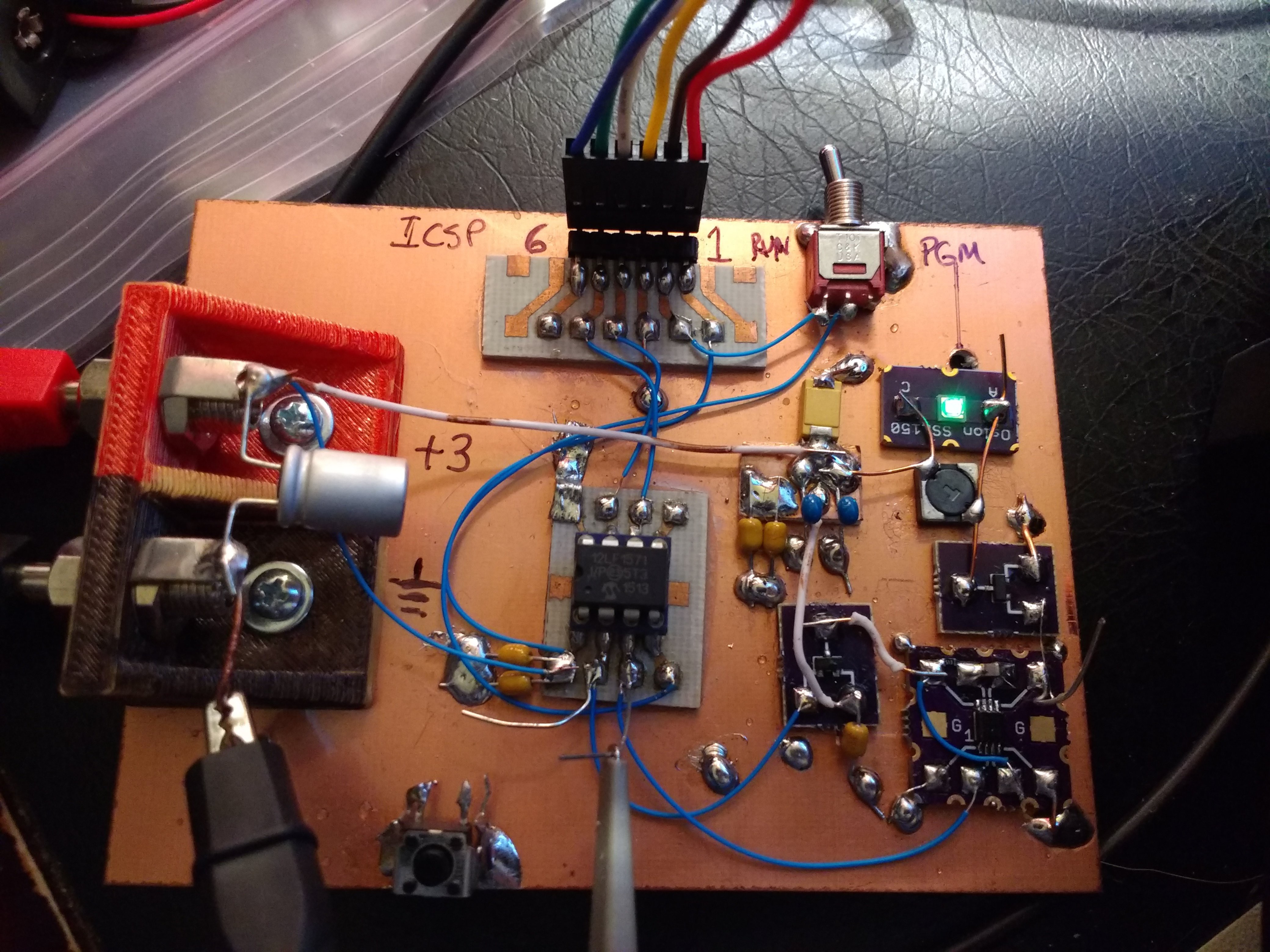
I prototyped the V3.0 circuit, re-using one of the V2.x breadboards. A few #Ugly SMD Adapters hold the 74LVC1G123 monostable, OSLON Signal Verde LED and SOT23 MOSFETs.
I tested the circuit at various pulse frequencies, and fit a line to the current drain. The resulting equation is:
where f is the pulse frequency. Since there is a fixed cost of 1.15uA, the circuit is more efficient for higher frequencies (larger current drains and brighter LED). This equation is close enough to get you in the ballpark when tuning for a specific current drain (or lifetime), but then you may need to tweak the frequency by a Hz or two to fine-tune.
Using the above equation and some manual fine-tuning, I came up with the following pulse frequencies for various run-times with a CR2032 cell. The cell capacity is assumed to be 220 mAh, and the run-time calculated as:
| Frequency (Hz) | Current (uA) | Runtime (years) | Notes |
| 262 | 25.0 | 1.0 | |
| 123 | 12.4 | 2.0 | |
| 78 | 8.15 | 3.1 | |
| 55 | 6.12 | 4.1 | |
| 42 | 4.96 | 5.1 | just flickering |
| 32 | 4.06 | 6.2 | noticeable flicker |
| 26 | 3.53 | 7.1 | noticeable flicker |
| 21 | 3.07 | 8.2 | noticeable flicker |
| 17 | 2.71 | 9.3 | noticeable flicker |
| 14 | 2.43 | 10.3 | noticeable flicker |
| 1 | 1.24 | 20.24 | exceeds shelf life |
I threw in that last point (1Hz pulse rate) just because it's the limit of the code as currently written. Since the shelf life of CR-series cells is commonly taken to be 10 years, I don't think run-times beyond that point make sense to predict.
Of course, the frequencies shown here are just examples chosen to correspond roughly to integer year run-times. You are free to choose any frequency in between or exceeding these. As a test, I turned the frequency up to 5kHz (it measured 4.65 kHz on the scope), and the circuit consumed 405uA. The LED was very bright.
The brightness at 1- and 2-year run-rates seems equivalent to the V2.0 circuit with the single LED I've tested so far.
Here's the PIC code. It's not in GitHub yet. The code just sets up the PWMs and then goes to sleep. The WDT is set for a 256-second timeout, at which point it wakes and the PIC resets to re-initialize the state just in case some bits rot over the years.
;;;
;;; tritiled_v30.asm:
;;;    PIC12LF1571 code for CR2032-powered LED glow marker
;;;
;;;  20171227 TCY

    LIST        P=12LF1571
 #include    <p12lf1571.inc>

;;;
;;; adjustable pulse frequency parameter
;;;
FREQ            equ .123


;;; calculated and fixed parameters
PHASE1          equ .0
PHASE2          equ .0
DUTY_CYCLE1     equ .2
DUTY_CYCLE2     equ .1
OFFSET_COUNT    equ .1
PERIOD_COUNT    equ (.31000 / FREQ)

  ERRORLEVEL -302
  ERRORLEVEL -305
  ERRORLEVEL -207

  __CONFIG  _CONFIG1, _FOSC_INTOSC & _WDTE_ON & _PWRTE_OFF & _MCLRE_OFF & _CP_OFF & _BOREN_OFF & _CLKOUTEN_OFF
  __CONFIG _CONFIG2, _WRT_OFF & _PLLEN_OFF & _STVREN_OFF & _BORV_HI & _LPBOREN_OFF & _LVP_ON


  ORG     0
RESET_VEC:
  nop
  nop
  nop
  nop
INTERRUPT_VEC:
  BANKSEL   ANSELA
  movlw     b'00000000'     ; all digital I/O
  movwf     ANSELA

  BANKSEL   LATA
  clrf      LATA

  BANKSEL   TRISA
  clrf      TRISA           ; set all lines as outputs

  BANKSEL   WDTCON
  movlw     b'00100101'     ; WDT 256s timeout
  movwf     WDTCON

  BANKSEL   APFCON
  movlw     b'00000011'
  movwf     APFCON

  BANKSEL   PWM1CON
  movlw     b'00100001'    ; PWM2 triggered with PWM1
  movwf     PWM2OFCON

  movlw     HIGH(PHASE1)
  movwf     PWM1PHH
  movlw     LOW(PHASE1)
  movwf     PWM1PHL

  movlw     HIGH(PHASE2)
  movwf     PWM2PHH
  movlw     LOW(PHASE2)
  movwf     PWM2PHL

  movlw     HIGH(DUTY_CYCLE1)
  movwf     PWM1DCH
  movlw     LOW(DUTY_CYCLE1)
  movwf     PWM1DCL

  movlw     HIGH(DUTY_CYCLE2)
  movwf     PWM2DCH
  movlw     LOW(DUTY_CYCLE2)
  movwf     PWM2DCL

  movlw     HIGH(PERIOD_COUNT)
  movwf     PWM1PRH
  movlw     LOW(PERIOD_COUNT)
  movwf     PWM1PRL

  movlw     HIGH(PERIOD_COUNT)
  movwf     PWM2PRH
  movlw     LOW(PERIOD_COUNT)
  movwf     PWM2PRL

  movlw     HIGH(OFFSET_COUNT)
  movwf     PWM1OFH
  movlw     LOW(OFFSET_COUNT)
  movwf     PWM1OFL

  movlw     b'00000011'
  movwf     PWMLD

  movlw     b'00000010'
  movwf     PWM2CLKCON
  movlw     b'00000010'
  movwf     PWM1CLKCON

  movlw     b'00000000'
  movwf     PWM1OFCON

  movlw     b'11010000'
  movwf     PWM1CON
  movlw     b'11000000'
  movwf     PWM2CON

  sleep  ; halt here - PWM generates pulses
  reset

  ;; fill remainder of program memory with reset instructions
  fill      (reset), 0x03fe-$
  END
Discussions
Become a Hackaday.io Member
Create an account to leave a comment. Already have an account? Log In.