 Ted Yapo
 The Good Stuff
TritiLED V1.0 is released under a CC-BY-SA License. See the license file in the zip packages for details:
- Gerbers are shared on OSH Park. Cost is $4.20 for 3 boards
- A BOM with DigiKey part numbers is shared on Google Docs. Cost is $4.99 per board in single-unit quantities (batteries included ;-). You can do much better if you make a bunch.
- Eagle design files are shared here on hackaday.io
- The PIC12F508 source code and hex files are shared here on hackaday.io
The design uses SMT parts, and although most of them can be hand-soldered, I don't think you can mount the LED without reflowing the board. Version 1.1 will allow mounting alternate (cheaper and hand-solderable) LEDs. Currently $2.76 of the parts cost is for the LED.
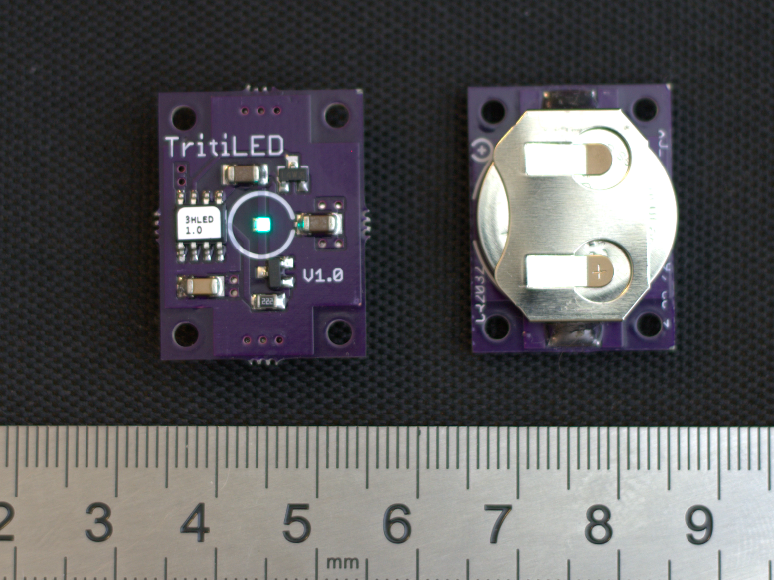
Here's what it looks like top and bottom (sans case):
History
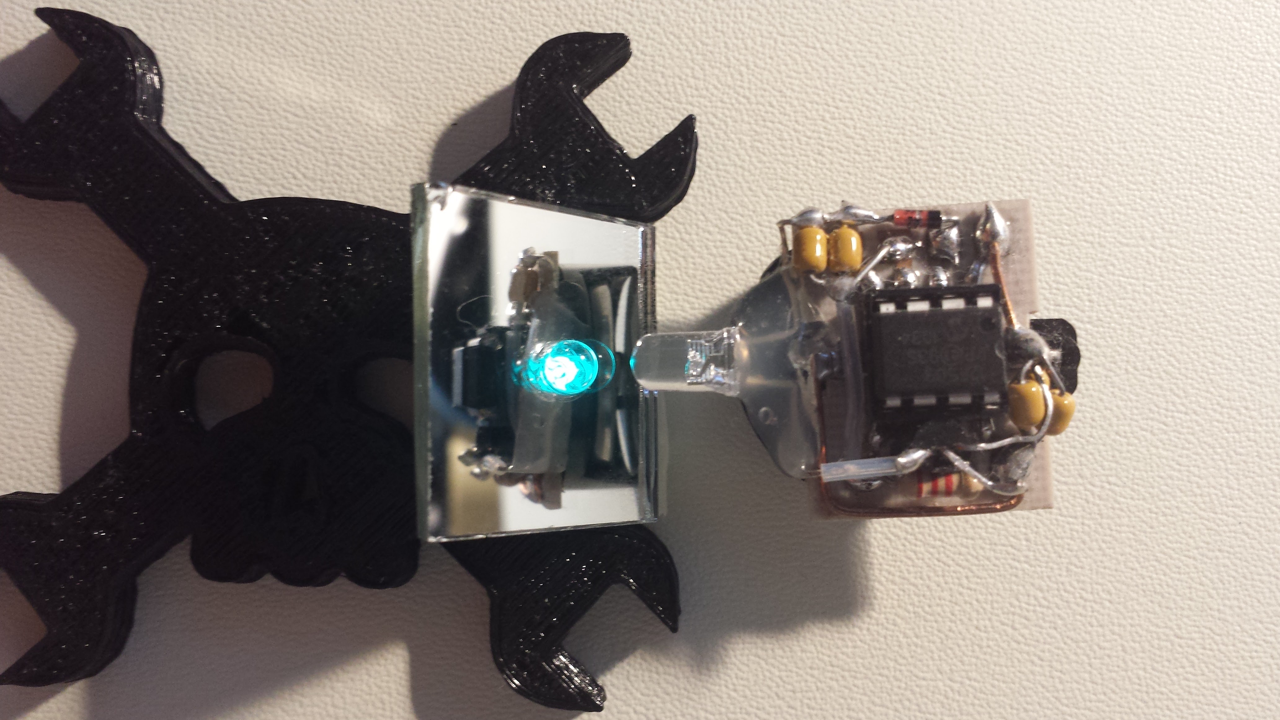
I built the first prototype in the Spring of 2015 with through-hole components and an ultra-bright cyan LED I purchased on ebay. I use this to read at night (not comfortably) when I don't want to wake my spouse. Here it is still running on the original battery over a year later (the CR2032 coin cell is underneath). I added the mirror so you could see the LED and the construction in one image.
 The design was inspired by a long-dead chip, the LM3909, which used a single-shot flying-capacitor DC-DC converter to flash an LED from a 1.5V cell. Here's a beacon I made c. 1998 using that part and the brightest LED I could find at the time. I think I've replaced the battery twice (the current one "expired" over two years ago) . It flashes once every few seconds - I got lucky with this picture.
![]() Hardware
Hardware
 Hardware
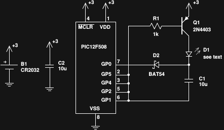
Here's the V1.0 schematic (there's an additional 0.1μF capacitor on the board; populating it is optional). Like the LM3909, this circuit is a simple charge pump that charges C1 up to the battery voltage, then connects C1 in series with the battery to (almost) double the voltage applied to the LED. Q1 switches the high side, while four PIC output pins are paralleled on the low side. During charging, these four pins are driven high, while GP0 is driven low to charge C1. The LED current is around 100mA for the pulse, and is limited by the semiconductor IV curves and parasitic resistances in the components.
The run time can be estimated with back of the envelope calculations as follows: the circuit consumes around 26μA at 3V. A CR2032 cell is rated for 225 mAh, yielding around 8,600 hours, or 360 days. In practice, you get a bit longer, because as the cell voltage drops, so does the device current. The original prototype has now been running over a year on the same cell. I'll include some more detailed information in a log about estimating efficiency and run-time.
Efficiency can be marginally improved by using a high-gain, low-Vce(sat) transistor at Q1. I've listed two alternatives in the BOM, along with the increased value for R1 this allows. I've tested all three transistors (2N4403, FMMT718TA, and DSS20200L), and I'm not sure the expensive ones are worth the cost in this case.
The capacitors are large to keep the voltage swings low; this raises efficiency. The well-known capacitor paradox illustrates that charging a capacitor all the way wastes half the initial energy; keeping the charge/discharge depth low wastes correspondingly less. Also, the capacitors are significantly de-rated: 10V caps in a 3V circuit. This is to overcome the tendency of ceramic capacitors to show reduced capacitance with applied voltage.
The LED is a cyan Luxeon Z (LXZ1-PE01). I chose this LED for two reasons besides its overall efficiency. First, its peak output is very close to the dark-adapted (scotopic) eye sensitivity peak at 507nm - ideal for illumination in very dark conditions. After 20 minutes or so of dark-adaptation, this LED becomes noticeably brighter compared with other colors. Other Luxeon Z LEDs (listed in the BOM and others) can be substituted. The LXZ1-PM01 green version is particularly interesting - the 530nm peak falls in between the scotopic (507nm) and photopic (555nm) human eye sensitivity peaks - this is a good trade-off for markers intended for mesopic (low light) vision. Other colors (e.g. red, blue) will light on the board, but they make inefficient visual markers. The second reason for choosing this LED series is the nominal current rating of 500mA. Efficiency typically drops when LEDs are over-driven (even pulsed), so this should be more efficient than over-driving a 20mA LED with the 100mA pulses. I need to build a photometer to measure the overall efficiency.
Software
The code is trivial. Here it is (also in the zip file):
;;;
;;; tritiLED.asm : PIC12F508 code for CR2032-powered 1+ year LED glow marker
;;;
;;;  4/23/16 adapted from earlier version c. 5/15 TCY
    LIST        P=12F508
#include    <p12f508.inc>
    __CONFIG    _MCLRE_OFF & _CP_OFF & _WDT_ON & _IntRC_OSC
        ORG     0
RESET:
        movwf   OSCCAL          ; update OSCCAL with factory cal value
        movlw   b'001000'       ; GP0, GP1, GP2, GP4, GP5 outputs
        tris    GPIO
        movlw   b'11010000'     ; WDT minimum time (18ms)
        option
MAIN_LOOP:
        movlw   b'000001'       ; GP1/2/4/5 L, GP0 H -> discharge capacitor
        movwf   GPIO
        nop
        movlw   b'110110'       ; GP1/2/4/5 H, GP0 L -> charge (sleeping)
        movwf   GPIO
        sleep
        goto    MAIN_LOOP
        END
After setting up the output pins, the code enters a loop blinking the LED for 3μs, then sleeping (charging C1) until the watchdog timer (WDT) wakes it 18ms (nom.) later. The approximately 55 Hz blink rate is noticeable, especially in motion, but tolerable. It actually seems to enhance visibility in peripheral vision when moving relative to the marker.
Programming
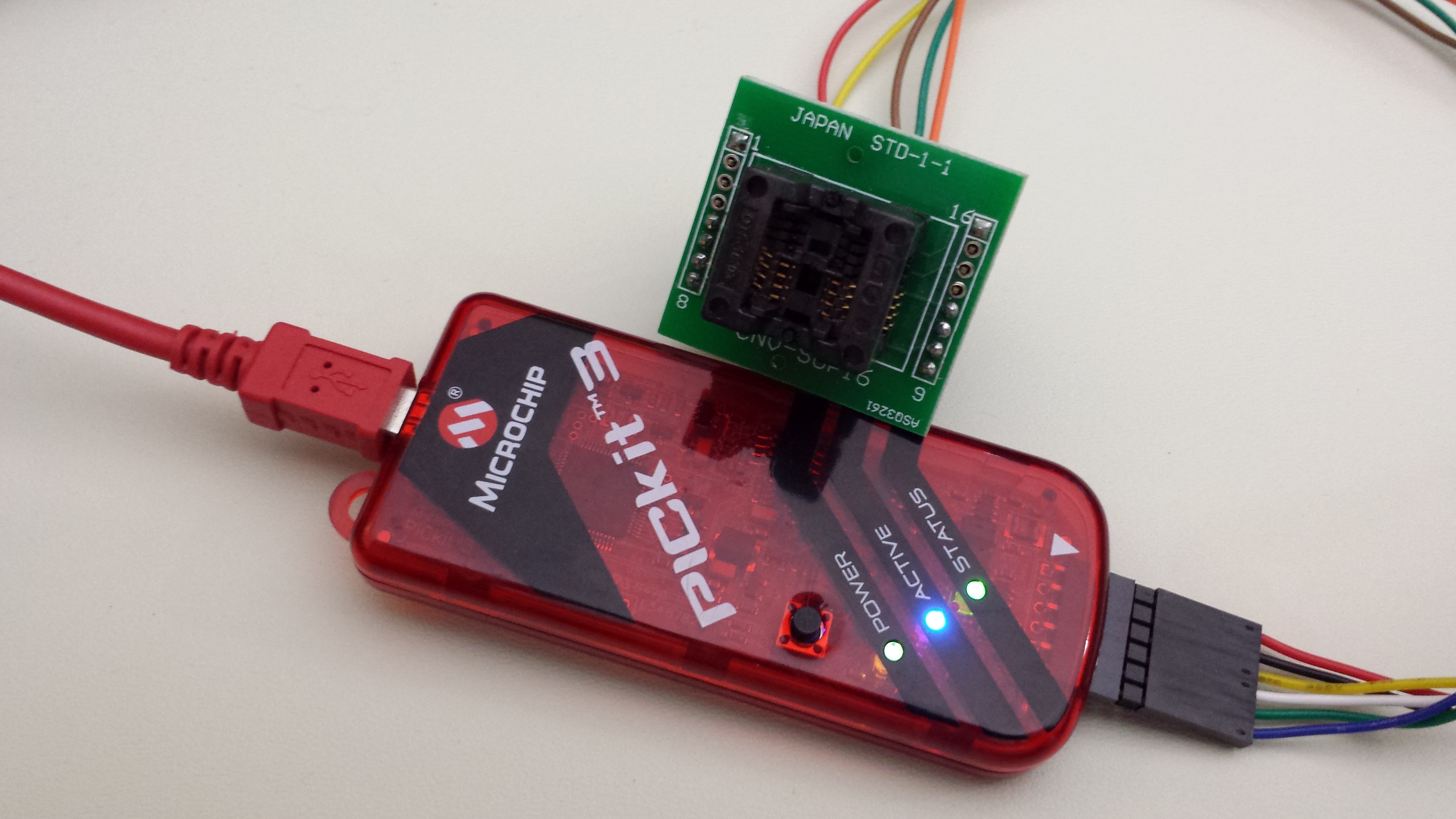
The PIC12F508 supports in-circuit serial programming (ICSP), but this design doesn't. This means that the SOIC-8 part has to be programmed before soldering on the board. For my prototypes, I bought an SOIC-8 socket at Adafruit, and hooked it to my PICkit3 programmer:
You can also order pre-programmed parts from DigiKey or directly from Microchip by supplying them the hex file. The setup fees are $50 at DigiKey and $29 at Microchip. I went through the initial process with Microchip - uploading the hex file, choosing the part, and selecting to go through the "verification" process. Four days later (still no setup fee paid), three sample programmed parts arrived via FedEx, with labels and everything (that's one of them on the purple board above). Now that's customer service! (Please don't abuse the free programmed samples - I really do intend to order some :-)
Next Up
- Modeling lithium primary batteries
- More accurate run-time estimation (other power sources, too)
- In-circuit measurements
- V1.1 - alternative LEDs
Discussions
Become a Hackaday.io Member
Create an account to leave a comment. Already have an account? Log In.