 Ted Yapo
First, I'd like to welcome @jaromir.sukuba to this project! He has been experimenting with this idea, and I'm excited to see what he comes up with.
It's been a while since I wrote anything here. Since last time, it was blogged on Hackaday - thanks to @Adam Fabio for the great writeup, and to the community for the helpful comments. One of the things to come out of the ensuing discussion was a confirmation that LEDs are indeed relatively inefficient at very low currents, which is what I suspected I was seeing.
So, it seems to design a better glow marker, I need to understand the characteristics of the LED better. LED datasheets are not very helpful in the ultra-low current regime, so I need to make some measurements. While I have a whole project (#Automated LED/Laser Diode Analysis and Modeling) devoted to building an automatic tester, I set up a temporary rig for these tests. To measure the LED forward voltage, current, and relative light output simultaneously, I assembled the following rat's nest:

I came up with the following simple circuit to precisely control the led current:
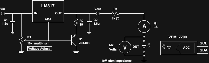
An LM317 voltage regulator is used to drop the voltage from a bench supply - the 10-turn pot allows fine control of the output voltage from 1.25 up to the dropout voltage. Q1 and R2 maintain the minimum required current draw from the regulator. R1 in conjunction with the variable Vout serve as a pseudo current source to drive the LED - you can change the current range by changing R1, whose exact value is not critical. A DMM on the uA range measures the current through the LED, while a 10M impedance voltmeter monitors the forward voltage. The small current burden of the volt meter is easily calculated and removed (I measured this circuit with no LED - it's pretty close to 10M impedance). Even unadjusted, the burden is a few hundred nA at the voltages involved.
To measure the relative light output, I optically coupled the LED to a VEML7700 I2C ambient light sensor from Vishay. It's a relatively new part aimed at automatic brightness control for televisions and similar devices. It's rather slow as optical sensors go, but has good low-light sensitivity and outstanding dynamic range and linearity. I'm using the same part in the automatic measurement device on the other project. Here's my optical coupling setup:
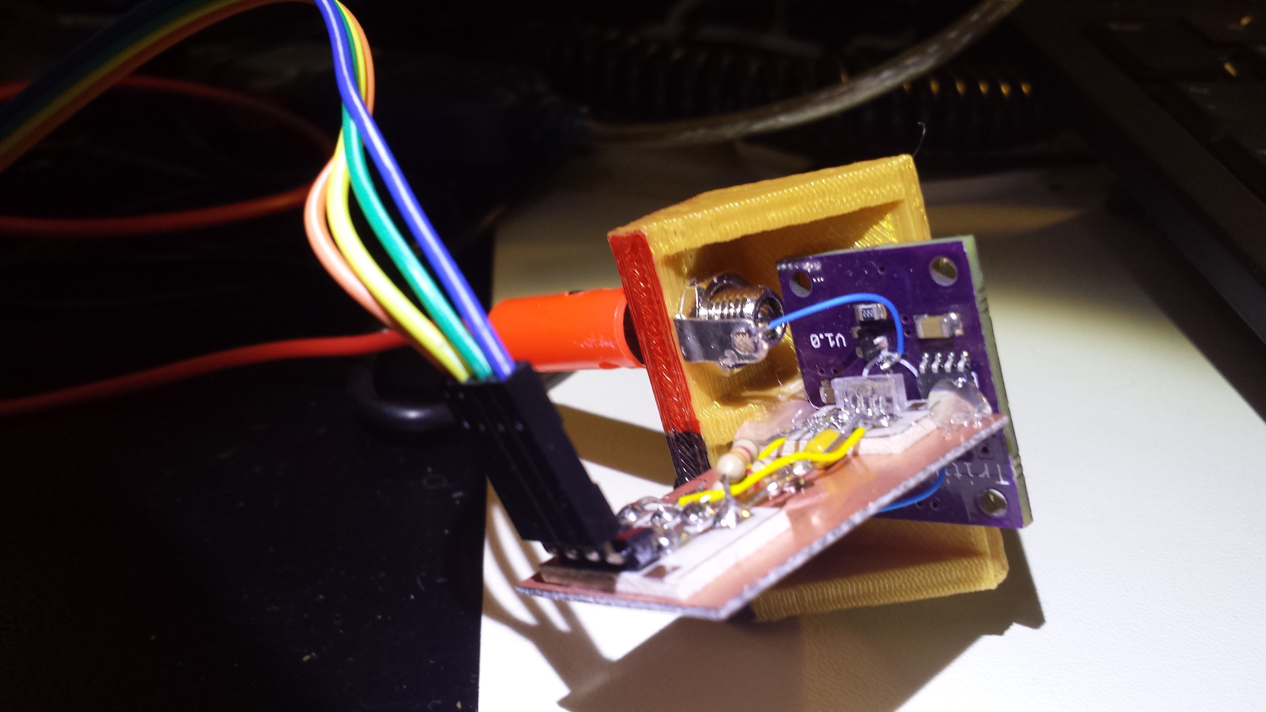
I positioned the sensor "near" the led and held the boards together with a few dabs of hot-melt glue. The whole assembly is shielded from ambient light under a black project box sealed to the table with a gasket cut from black foam. With no LED current, the sensor reads 0.0000 lx even with early-afternoon sun streaming into my office. Of course, with this "random" optical coupling, we can only collect relative output measurements, but that's enough to examine overall efficiency.
I took some time to collect a bunch of data for low currents (can't wait to automate this), and came up with the following graph:
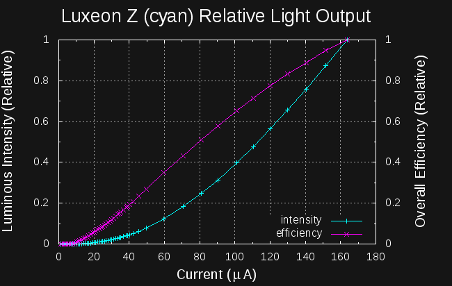
The cyan line shows the relative output of the LED vs. current. There is zero detectable output from the LED until around 7.5uA, at which point the output increases very slowly with current until it becomes roughly linear well above 100uA. I calculated the overall relative efficiency (magenta line) with:
Where Ev is the illuminance (lx) detected by the VEML7700, and Vf and I represent the forward voltage and current through the LED, respectively. I scaled the resulting measurement by the highest value to come up with a relative measure, since the absolute value is completely uncalibrated. As you might expect from the relative intensity curve, the relative efficiency at very low currents is also terrible. This data would suggest that the LED is around 10x as efficient at 120uA as it is at 20uA.
It's easy to see why driving this particular LED with 26uA of DC current results in such lousy output. If I had seen these plots while recording the data points, I would have continued to higher currents. When I find some time, I'll do just that. Unfortunately, the TritiLED 1.0 PCB wasn't designed to dissipate any power from the LED (it's consuming tens of uW in normal operation), so I can't go up to 100mA on the current axis for fear of damaging the LED. Or, maybe I can come up with some other way to mount the LED for testing.
Discussions
Become a Hackaday.io Member
Create an account to leave a comment. Already have an account? Log In.