 Ted Yapo
I had some news and a few ideas I'd like to get out there, even though I haven't had enough time to flesh everything out yet.
New Team Member
I'd like to welcome @tony ozrelic to the team! Tony and I have been discussing some promising new circuit topologies for the design (more about this below). I'm really excited that people are experimenting with these things!
Lime Luxeon LEDs
I ran across another Luxeon Z LED - the LXZ1-PX01 in "lime" color. This LED is interesting for a few reasons. First, it boasts an output of up to 200 lm, compared to around 70 for the cyan, or 100 for the green. It achieves this impressive performance by using a blue or UV emitter (not sure which) and a greenish phosphor, similar to the construction of white LEDS. The lumen ratings are relative to the photopic curve, of course, so it may not be as efficient for dark-adapted eyes (scotopic vision). When I find some time, I'll digitize the spectral curves from the respective datasheets and evaluate them against the photopic and scotopic sensitivity curves to see how these LEDs might compare in the dark. In any case, this sounds like an interesting LED to test. The bad news: $4.20 each. Ouch.
DIY Phosphor LEDs
So, the lime LED got me thinking. What about driving a UV LED with a TritiLED-like circuit, and using it to excite a glow-in-the-dark phosphor? If the phosphor has a decent persistence time, you don't have to worry about rapidly pulsing the LED - maybe a few times a second would be enough to continuously re-charge the glow. I have some glowing plastic stars left over from making bedroom ceiling constellations and a bag of activated ZnS powder from spinthariscope experiments that I can run some tests on. You might even be able to convert wristwatches with phosphorescent hands to tritium-like performance with a strategically-placed pulsing UV emitter.
I have no idea what level of efficiency to expect from this kind of setup, but it seems like a fun thing to try. The really bad news: UV Luxeon Z (LHUV-0390-0400) emitters are $15 each. Bigger ouch.
New Topologies
Tony sent me an interesting pulse circuit he came up with:
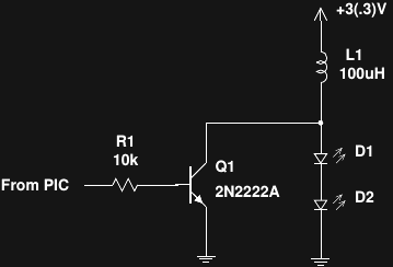
It's a wonderfully simple single-shot inductor boost converter. The forward voltage drop of the series LEDs is large enough to prevent current flow between pulses. To pulse the LEDs, the transistor is briefly turned on, ramping up current in L1. Once the transistor switches off, the inductor voltage rises to maintain the same initial current flow, now into the LEDs. As we saw two logs ago, the sawtooth-shaped current pulses generated by a circuit like this can be adjusted to give nearly optimal LED efficiency. Very convenient.
I couldn't sleep after I saw this circuit, and ended up playing around in LTspice with simulations until I came up with this variation using a single LED:
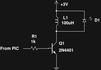
If you took the two photon arrows off the LED symbol, this would be a solenoid/relay driver circuit with a protective catch diode. Turning the transistor on energizes the inductor, which then discharges through the LED after the transistor turns off. It just doesn't get any simpler than this. Tony built one of these, too (I'm still in simulation-mode), and reported that it was brighter than the two-LED version. It would also be cheaper, especially with Luxeon LEDs.
The one thing that might drag efficiency down here is the base current, which is wasted. Using a MOSFET might help, but driving the gate capacitance might negate any gains - I'm not sure yet. Another alternative which I've been playing with in simulation uses a Darlington pair with a couple of diodes to improve turn-off time. This circuit forces the base current of the driver transistor through the inductor, so it's not wasted:

Here, D1 and D2 speed the turn-off and seem to improve the overall efficiency, at least in simulations. This idea is only half-baked, so shoot holes in it if you can.
In any case, some version of this single-shot inductive boost idea seems like just the thing for improving efficiency. With these circuits, the overall LED brightness and power consumption are likely to be strong functions of battery voltage, so some smart software on the PIC is probably in order. PICs with an ADC and internal voltage reference could be programmed to monitor the battery voltage (maybe reading it every few seconds) and adjust the pulse duration using a pre-calibrated lookup table to maintain an optimum LED current. A second lookup table could provide a duty-cycle adjustment to maintain a constant brightness level.
Datasheet Scraping for the Luxeon Z
I'm still waiting for properly heat-dissipating PCBs to test the Luxeon Z LEDs at high currents, but I pulled the datasheet-graph-digitization trick again to see what Lumileds themselves implicitly say about the relative efficiency of their LEDs. I grabbed these plots from the datasheet:
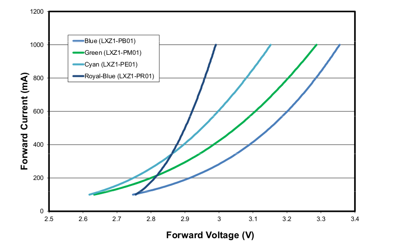
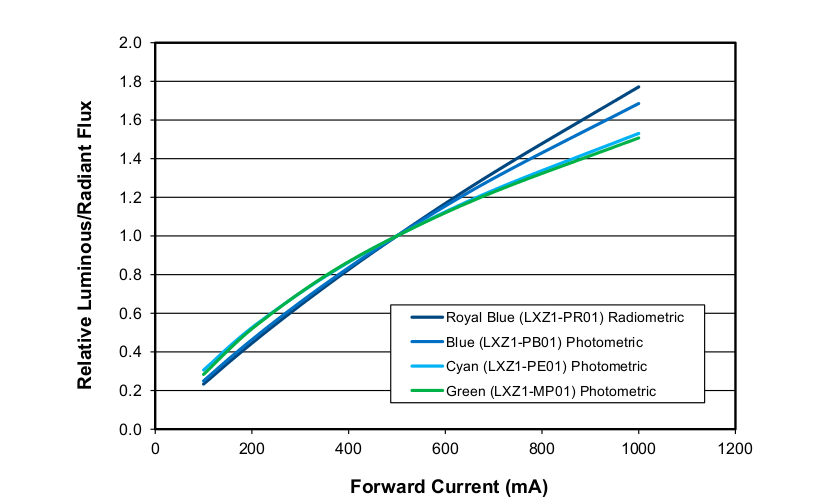
then digitized the cyan curves with the awesome open-source engauge-digitzer, and calculated the relative efficiency:
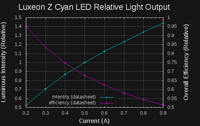
As you can see, this LED is almost 2x as efficient at 200mA as it is at 1A (the maximum rated DC current). As expected, the data doesn't extend all the way down to show the efficiency peak somewhere below 200mA. My original circuit pulsed the LED at about 100mA. Now I'm really curious as to how close I (accidentally) got to the ideal!
Discussions
Become a Hackaday.io Member
Create an account to leave a comment. Already have an account? Log In.
Oh, you can ignore my Darlington idea. I looked at this log this morning, and realized the Darlington never has a Vce drop less than one Vbe. So much for that...
Are you sure? yes | no
That's one point for the MOSFET idea :-)
Are you sure? yes | no
I tried 2N7000 as well as 2N2222A in the first two circuits above. LED(s) were a bit dimmer for the NFET compared to the bipolar. I removed the drive resistor for the NFET version, no change. Dialing the power down to 2V caused a really dim light output for the NFET version, probably not enough gate drive.
Are you sure? yes | no
Yeah, that sounds like what I'd expect from the datasheet. @Yann Guidon / YGDES has a point, though - some more modern parts with tiny gate capacitances, super-low thresholds, and minuscule Rds would be worth investigating. I'd be willing to bet you can beat BJTs here, but I don't know how much it would cost. That's why I don't like FETs - the landscape is always changing with better devices that can do what you used to think they couldn't. The 2N2222 was seven years old when I was born, and you still find it in designs. Reliable mediocrity is a good thing in engineering :-)
I am a little scared by Yann's recent discoveries that some LEDs have reverse-protection diodes built in. That would preclude the single-LED inductor circuit above. I'll have to test the ones I have here.
Are you sure? yes | no
MOSFET doesn't cost that much.
NTE4153NT1G $0.38 at QTY 1 Ron = 0.275 ohms (max) for VGS=2.5V . So at 500mA, that's 0.138V drop compared to a 2N2222 at around 0.3V (typ) at 500mA.
http://www.digikey.com/product-detail/en/on-semiconductor/NTE4153NT1G/NTE4153NT1GOSCT-ND/687115
AO7404 $0.44 at QTY 1
http://www.digikey.com/product-detail/en/alpha-omega-semiconductor-inc/AO7404/785-1086-1-ND/1856029
My favorite DMG1024UV dual (you can run it in parallel or us a two separate MOSFET) is $0.39 at QTY 1. That's why I prefer it over singles.
http://www.digikey.com/product-detail/en/diodes-incorporated/DMG1024UV-7/DMG1024UV-7DICT-ND/2270855
Are you sure? yes | no
To be fair, it's not my discovery but @al1's :-) Then it's a matter of using the diode to your advantage. The default 0.7V diode can be paralleled with a better 0.2V schottky type to increase the performance.
Are you sure? yes | no
Why use a bipolar transistor ? despite the gain, there is still loss in the base current. Even a 2N7000 (N-channel MOSFET) would avoid this... And gate capacitance has gone pretty low, for modern references. The gate charge is also proportional to the driving voltage and you don't need to drive more than a few 10s of mA so there is no problem driving the gate at 2V (lower gate charge, less Miller, etc.)
Are you sure? yes | no
Furthermore, from (other's) experience with TTL design and their discrete implementation, bipolar transistors' base charge is also a problem, hence the traditional Schottky diode that prevents saturation.
Are you sure? yes | no
You can also speed the turn off (even out of saturation) with a reverse diode across the base resistor to pull out the base charge at turn-off. Not as much speed gain as preventing saturation altogether, but you get lower Vce.
Are you sure? yes | no
Yes, it might be better to use a MOSFET here; I don't know yet. The 2N7000 might be marginally OK, except the Vgs threshold is 3.0V max, which wouldn't work in corner cases or with semi-discharged cells, but other MOSFETS might be really good :-)
I think it's a trade-off between MOSFET cost, input capacitance (limiting the switching speed given the anemic PIC output drivers), and Rds losses vs lower-cost BJT's with charge-storage turn-off time lag and base current and Vce losses. It's not obvious which is the winner; I need to choose some specific devices to go head-to-head.
@K.C. Lee recommended the DMG1024UV dual as a MOSFET, and possibly the NLAS4157 analog switch as drivers. I have some on order to try.
Are you sure? yes | no
The part isn't optimized for below 3V. VTH is 1V (min), 2.1V (typ), 2.5V (max) that is for 250uA at 25C.
2N7002 datasheet: ID vs VGS plot, ID is around 50mA when VGS is at 3V.
FYI Diode Inc DMG1024UV: Cheap, comes in a dual. Only draw back is packaging. There might be other parts with similar or better specs, but I was searching for smallest, cheapest and best part for a project.
VTH = 1V (max), RON = 0.4R (typ) 0.6R (max) at VGS = 2.5V. Ciss = 60.67pF.
Are you sure? yes | no
I've already got packaging problems if I stick with the Luxeon Z LEDs ... what's one more going to matter :-)
Are you sure? yes | no
I think the bottom line is that I need to simulate and/or prototype to determine the difference this makes. If it makes a big difference, it should be obvious, and if the difference is small, it doesn't matter.
Are you sure? yes | no