 Ted Yapo
I have been thinking of ways to avoid the issues of the inductor/LED arrangement, which constrains the current pulse width. This morning, I worked through some LTspice simulations using tapped inductors to get different input/output current ratios:

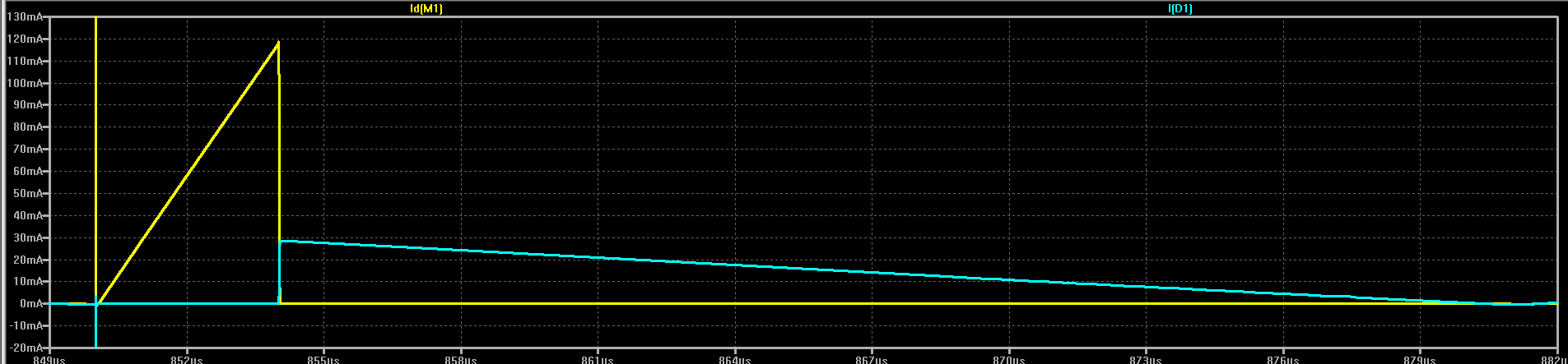
In the schematic, L1 and L2 are magnetically coupled by the K1 coefficient (1) simulating a tapped inductor - this isn't the same as two separate coils. In this case, L1 is smaller than L2, so the input current pulse will be larger than the output. As a consequence, the output pulse will be longer. In this example, the input current pulse reaches a maximum of 120 mA, while the output pulse maximum is 30 mA:
The ratio of the current pulses is determined by tap position. Tapped at the bottom of the coil, this is the original circuit which produces equal input and output current. Moving the tap "upward" makes the input pulse larger while reducing the current in the output pulse and extending the duration.
This could be useful for matching the output to the optimum current to drive a particular LED.
Of course, this presents some difficulty for using off-the-shelf inductors, the majority of which are do not come with taps. Homebrew inductors are easy to make, though, and it might even be possible to add an extra winding on a commercial inductor to create the tap.
I don't know how practical this all is, but it's another possible trick to use.
Discussions
Become a Hackaday.io Member
Create an account to leave a comment. Already have an account? Log In.
The project is about extending battery life, so you would need to consider the effects of high internal resistance of a near dead battery in you simulation. You want to trade off on time vs current by use as large an inductance to reduce the peak current. They however have higher internal resistance and lower saturation current of the high value inductance.
Adding a large value low ESR cap to supplement the charges would help a bit.
Reusing the core of a common mode choke might be a quick way of getting high inductance with fewer turns. You also get thick wires out of it. :) The core is lossy at high frequency, but that shouldn't be an issue. You want to use bifurcation to increase the coupling as common mode chock is the opposite. It tries to decrease coupling to have leakage inductance act as diff mode filter.
Are you sure? yes | no
The 10uF MLCC on the current version will actually run it for a few seconds after the battery is removed, so it does a good job as a reservoir for the pulse current.
The battery internal resistance on lithium primary cells is not that bad. Especially when you are drawing so little current. I intentionally add another 100 ohms of resistance to the battery for protection, and pay a tiny fraction of a percent efficiency penalty.
The combination of low average current and relatively large MLCC make the whole thing fairly insensitive to the internal resistance of the cell.
Yes, bifilar windings are a good idea. I have about 10 pounds of cores of all sizes and materials in ferrite and powdered iron - I'm sure I could prototype something, but designing using off-the-shelf magnetics would be preferable.
I should do a thorough analysis of the effect of internal resistance. I'm sure it's small, but it would be nice to prove it :)
Are you sure? yes | no
Two problems I see with this.
1) V = I * dI / dt. Did you check the voltage on the drain when the FET turns off?
2) Have you heard of the "capacitor paradox" (that isn't really a paradox)? You've created the inductor version of that. By my reckoning, the energy in L1 is 720 nJ at the peak of the ramp, and the energy in L1+L2 just after the FET opens is 490 nJ.
That's assuming discrete inductors. If it's tapped, there's going to be significant amounts of mutual inductance and that's basically an autotransformer. I'd need to review my circuit analysis textbooks to remember how to model mutual inductance.
Are you sure? yes | no
With the coupling, it's an autotransformer.
Maybe it behaves a little like a T-coil using the LED capacitance:
https://ibis.org/summits/may11/ross2.pdf
I've thought about the capacitor paradox before - you get around it by using shallow charge/discharge cycles, or by using resonant charging with an inductor, as I recall. Interesting stuff. I'd be psyched if I had stumbled onto the inductor paradox here. I'll have to think about that.
The voltage on the drain is good (held in check by the LED):
According to the LTspice simulation, the energy drawn from the supply is 14.14 nJ integrated over the 1ms run (20 pulses), while the energy delivered to the LED is 14.03 nJ. I think that's just parasitics (like MOSFET losses) rather than a theory problem. The K coefficient in spice models mutual inductance:
https://cds.linear.com/docs/en/lt-journal/LTMag-V16N3-23-LTspice_Transformers-MikeEngelhardt.pdf
But, I haven't played with this very long. There could easily be something I'm missing.
Are you sure? yes | no
It's not really anything to be psyched about. The capacitor "paradox" is the situation where a charged capacitor is connected in parallel with an uncharged capacitor. After the voltage balances, the energy left in the capacitors is less than the energy that was in the original capacitor.
The inductor version of this is a charged inductor placed in series with an uncharged one. After the current balances, the energy left in the two inductors is less than the energy that was in the original charged inductor. Mathematically, it's literally the exact same problem, just with different components. The inductor version is only less well known than the capacitor version because inductors are less commonly used.
The energy in a 100 uH inductor with 120 mA of current is 720 nJ. The energy in a 1.1 mH inductor (100 uH + 1 mH) at 30 mA is 495 nJ. You lose 225 nJ in the in the impulse when the MOSFET shuts off. That's the inductor version of the capacitor "paradox".
Just like connecting two capacitors in parallel causes a large current spike while the voltage equalizes, connecting two inductors in series should cause a large voltage spike while the currents equalize. Your graph looks wrong. There should be a huge voltage impulse when the MOSEFET turns off. Are you measuring the voltage of the LED anode and not the MOSFET drain?
Are you sure? yes | no
@MarkRD Short reply because I only have my phone 150 mi from home.
You treat them as two separate inductors to get 1.1mH, but that's inaccurate.
The way they are modeled here with a coupling coefficient of 1 is equivalent to turns on the same core, which is different from separate, uncoupled inductors.
Lets assume the 100uH portion has N turns. Then the 1000uH part has sqrt(10)*N. This is because inductance is proportional to the square of the turns. Both sections together then have N(1 + sqrt(10)) turns. This is equivalent to an inductance of (100 uH)(1 + sqrt(10))^2 = 1732 uH. Not 1100 uH.
This is just like when you connect both windings of a 1:1 transformer in series, you get 4x the inductance, not 2x. (Unless you get the phase wrong, then you get a non-inductive wirewound resistor.)
A 1732 uH inductor at 30 mA contains 779 nJ. It's not exactly equal to the 720 nJ you calculate for the 100uH because the currents aren't exactly 120 mA and 30 mA - those are just estimates I eyeballed off the plot. If I got the currents right, the energies would be equal.
There's no paradox here.
I would just be psyched because I had never heard of the "inductor paradox" before (unlike the cap one), and would have liked to have bumped into it accidentally. But this isn't it.
Yes, I'm sure the waveform was probed correctly. I can post the LTspice file tomorrow if anyone else wants to look.
Are you sure? yes | no
Somehow, the waveform I posted in a comment below doesn't show now. I'll have to fix it tomorrow.
Are you sure? yes | no
I understand now. I didn't see the K directive that couples the inductors together, and you had cropped of the part of the screenshot that has the node name.
I'll fire up my LTSpice and see what's going on.
Are you sure? yes | no
@MarkRD I forgot to save the original simulation, so had to re-create it to capture the waveform. It ended up with different node numbering, so I cropped it to avoid confusion. I know I can label the nodes manually, but I'm lazy :)
Yes, the K coefficient is key. Of course, it won't really be 1, but probably close.
Are you sure? yes | no
Yep, that K directive really changes it. When I get rid of it so that they're independent inductors, I get the huge spike I was expecting.
If you're going to do something like this, make sure you check the reverse voltage. Because the coupled inductors form a transformer, I'm seeing about 12.5V reverse voltage on the LED during the charging phase.
Are you sure? yes | no
@MarkRD Reverse voltage is a very good catch. 12.5V is probably a deal-breaker for a lot of LEDs. I seem to remember seeing 5V max specs and thinking I was in the clear with the previous circuit.
I guess thinking of it as an autotransformer, you should expect a large voltage induced.
Maybe if you keep it to smaller ratios like 1:1, which are more likely to be commercially available (sold as transformers), then the reverse voltage isn't that high.
Are you sure? yes | no