 Ted Yapo
Here's the circuit for V3.0
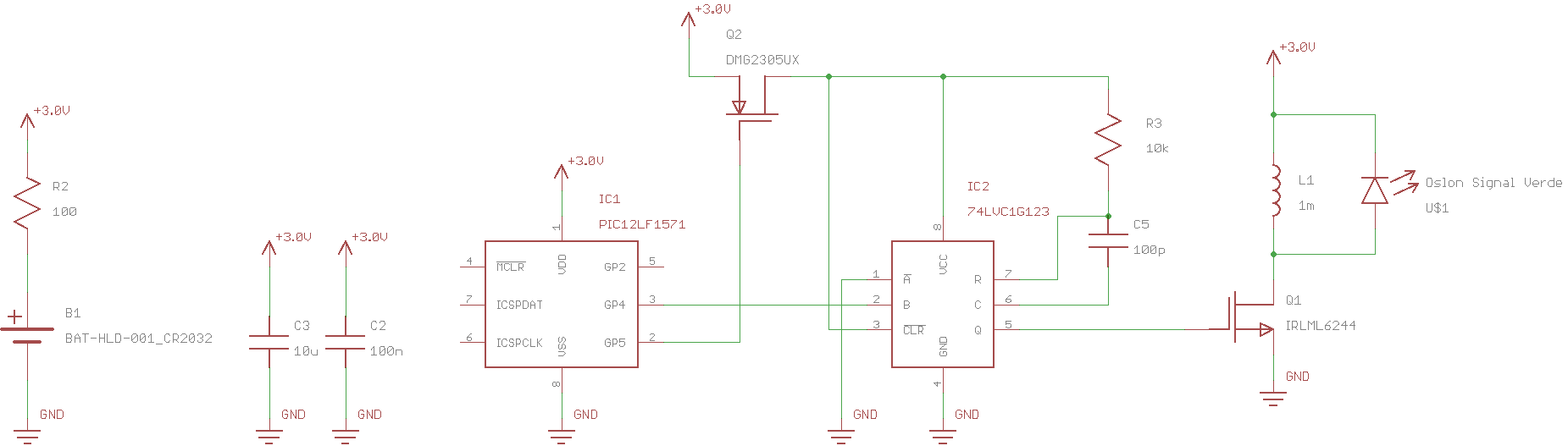
In this design, a PIC12LF1571 controls the LED using two 16-bit PWM outputs. The PWMs continue to run even in sleep mode, and to save power, are running from the 31kHz LFINTOSC. The PIC will only wake every few minutes or so to re-initialize any RAM that may have become corrupt, and maybe change the PWM frequency based on the supply voltage (to maintain a constant brightness).
The downside of using the PWMs running from the 31kHz oscillator is that that shortest pulse that can be created is around 30us, far too long for most LED/Inductor combinations. So, the PWM output is used to trigger a 74LVC1G123 monostable which creates the necessary short pulse. In the first batch of boards, I'm using a OSLON Signal Verde LED, which requires a peak current of around 4mA for optimum efficiency. Using a 1mH inductor, the required pulse width is 1.2us, so a 100pF capacitor and 10k resistor are used for the 74LVC1G123's RC.
The big problem with the 74LVC1G123 is that the quiescent current drain is specified at 20uA. This is several times the entire current budget for the glow marker. So, to save power, the PWM1 output is used to gate power to the 74LVC1G123. The normally-high PWM1 output goes low around 30us before the LED pulse, applying power to the monostable through Q2, a P-channel MOSFET. PWM2 is synchronized to PWM1, and triggers the monostable once it has had a chance to power-up. The datasheet for the 74LVC1G123 mentions that it contains circuitry to prevent glitches during power-on.
The notion of using the PWM instead of code to drive the LED pulses was suggested by @MarkRD in late July of this year: the rest of the design follows from that.
Here are some scope traces from a breadboarded version:
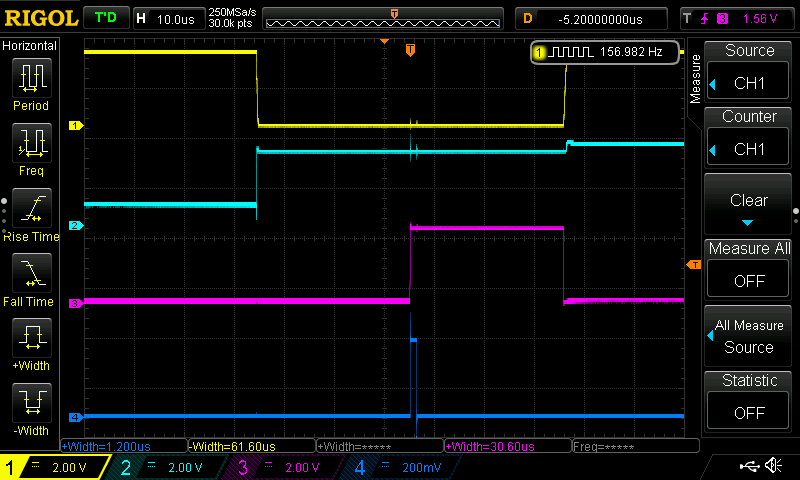
The PWM1 output (top trace; yellow) is normally high, and is pulled low to apply power to the monostable. The monostable's Vcc supply (second trace; cyan) rises quickly as the P-MOSFET switches on. PWM2's output (third trace; magenta) is synchronized to PWM1, and occurs 30us after the monostable is powered on. The monostable output (bottom trace; blue) is a nice 1.2us pulse (actually measured as 1.36 on a zoomed-in view).
The measured current drain for just the PIC PWMs (no monostable) is 1.12uA with an output frequency of 150Hz. Adding the monostable brings the total drain to 1.98 uA at 3V. The current drops significantly at lower supply voltages. I measure 1.27uA with the monostable at 2.0V.
Although these currents aren't quite as low as I'd like, this architecture brings a lot of flexibility. Through the choice of the RC time constant for the monostable and inductor value, the peak current can be accurately matched to the efficiency curve of the LED. Once that has been done, the LED brightness and total current drain can be adjusted with very fine control by changing the 16-bit PWM frequency. At around 150Hz blink rate, the brightness (and current) can be adjusted in sub-1% steps. So, you can use a wide variety of LEDs, with the circuit tuned to the characteristics of each one.
I haven't built a complete prototype yet, so there may still be some surprises. I have some PCBs coming from OSH Park, and although they need a bit of rework (I found a bug), I should be able to complete a few prototypes soon. A corrected PCB has already been ordered.
Discussions
Become a Hackaday.io Member
Create an account to leave a comment. Already have an account? Log In.