 Ted Yapo
The V3.0 circuit allows you to tune the pulse width and repetition rate independently. Throwing in inductor size and peak current, and you have a four dimensional space in which to choose an operating point. To simplify the design process, I condensed three of the variables (pulse width, inductor size, and peak current) into a nomograph showing the efficiency of each pulse:
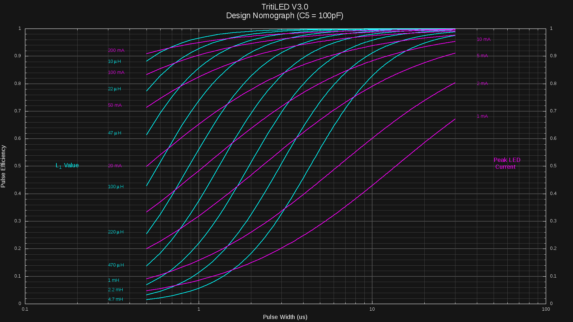
The y-axis shows the efficiency of each LED pulse, just considering the per-pulse overhead of the PIC and monostable. The overall electrical efficiency will be somewhat less than this value due to an approximately 1.1uA baseline current for the PIC, plus any losses in the inductor and MOSFET. This chart also assumes a 100pF capacitor for the monostable; the resistor is chosen based on the desired pulse width from the formula:
I experimentally determined k = 1.28 for C = 100pF at 3V (the datasheet charts don't include this value).
How To Use
Don't panic.
The chart is easy - you use it to choose an inductor size and pulse width based on the peak LED current you want. The vertical axis reads the pulse efficiency, which is to say, how much energy goes into the LED vs how much is wasted in the PIC and monostable during a pulse. You want to maximize this efficiency. The horizontal scale shows the monostable pulse width.
There are two sets of lines on the chart. The cyan lines, labeled on the left, represent different inductor values. For example, following the 470uH line to a 3us pulse width shows that around 84% of the energy used during a pulse can get to the LED; the remaining 16% being wasted by the PIC and monostable.
The magenta lines (labeled on either side) represent the peak current through the LED. Using the example above of 470uH and 3us, we see that this point is intersected by the 20mA line, so the peak current through the LED for this combination is 20mA.
In practice, you typically know the desired LED peak current, and want to choose the inductor and pulse width. So, here's another example: you know your LED is most efficient with peak currents of 50mA. To get the most efficient drive, you examine the 50mA magenta line, and evaluate each possible inductor value. If you have a 1mH inductor available, you can get 50mA pulses at about 17us with 98% efficiency. On the other hand, if you choose a 100uH inductor, you'll end up with around 1.7us pulses and 88% efficiency. That's it.
Complications
So, the answer seems easy: choose the 1mH inductor, which is more efficient. In reality, you may want to choose a smaller inductor since it will allow you to run at lower currents without visible flashing. For a given current, using a larger inductor means more energy per pulse, so for a specified current drain, you will need to choose a slower flash rate, which may become visible.
A second complication is that the optimum LED current may not turn out to be the best choice considering the monostable pulse overhead. This is especially true for small LED currents. As an example, the OSLON Signal Verde LED I have been testing has a current around 4mA for peak efficiency. Unfortunately, driving this LED at 4mA with a reasonable 1mH inductor results in around 40% pulse efficiency (60% of the energy used by the PIC and monostable). So, you can do better by choosing a larger current: you trade electrical efficiency for LED efficiency to get a better overall efficiency. You can see this tradeoff directly in a plot of the three efficiencies (electrical, LED, and overall) vs pulse width for a 1mH inductor:
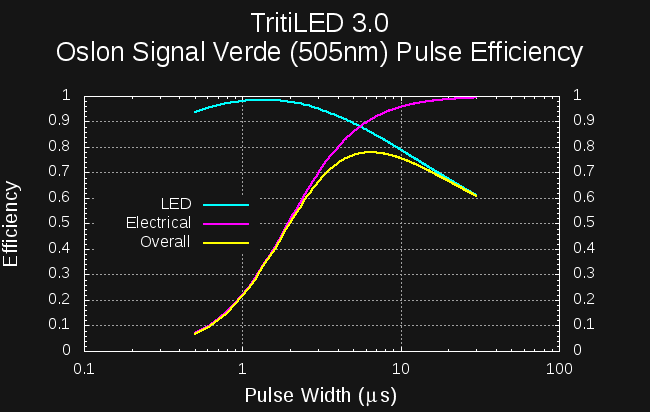
Although the LED would perform best with a pulse of approximately 1.5us, and the rest of the circuit at 10 or more, the combination performs best at around 6.5us. Here, the electrical efficiency is over 90%, while the LED efficiency is 86%. Multiplying the two reveals that the circuit is emitting 78% of the possible light for this LED given this current drain.
Evaluating the performance of such a choice requires detailed information about the LED efficiency curve. I've written some Octave code to incorporate the measured efficiency curves, and the result is that you can achieve a maximum 91% electrical efficiency by driving this particular LED at 19.5 mA, using a 1mH inductor with a 6.5us pulse. This 91% efficiency is a limit in the case of high pulse rates (equating to hight brightness and high current drain). Considering the fixed PIC overhead, the overall electrical efficiency drops to 83% at a 2-year CR2032 lifetime (12.5 uA) with a pulse rate of 164 Hz. Going to a 1-year CR2032 lifetime (25uA) increases the electrical efficiency to 87%, using a pulse rate of 344 Hz.
Since the pulse frequency is determined by a 16-bit PWM, it can be adjusted very accurately. For example, changing the pulse frequency to 56Hz drops the current drain to 5uA, for a 5-year runtime on a CR2032 at an electrical efficiency of 71%. Of course, the LED is much less bright. If you extend the runtime much further, the flashing becomes noticeable. For example, you can set the pulse frequency to a visibly flashing 21Hz, reducing the current to 2.5uA, and the LED should stay lit for 10 years on a CR2032. At this point, the PIC overhead really starts to take a toll: the electrical efficiency at this 10-year rate is only 52%. But, the light stays on for a decade.
Do I really have to go through all that??!
No. I've chosen a small set of LEDs I'm designing for, and will choose all the components for each one making what I think are reasonable trade-offs. I'll publish complete designs for each one after they've been tested and confirmed.
As I release the designs, I'll also present the measured current drains vs pulse frequencies and estimated efficiency numbers for a variety of run-times from 1 to 10 years on a CR2032.
Discussions
Become a Hackaday.io Member
Create an account to leave a comment. Already have an account? Log In.