 Ted Yapo
I've finished the design and tuning for the OSLON Signal Verde LED flavor of V3.0. The design is documented here; as I tune the other LED flavors, I'll add to this log. Key features of V3.0 are the ability to finely tune the brightness/lifetime trade-off, build-time configuration for different optimal LED drive currents, and using a "5g" plastic jar as a case.
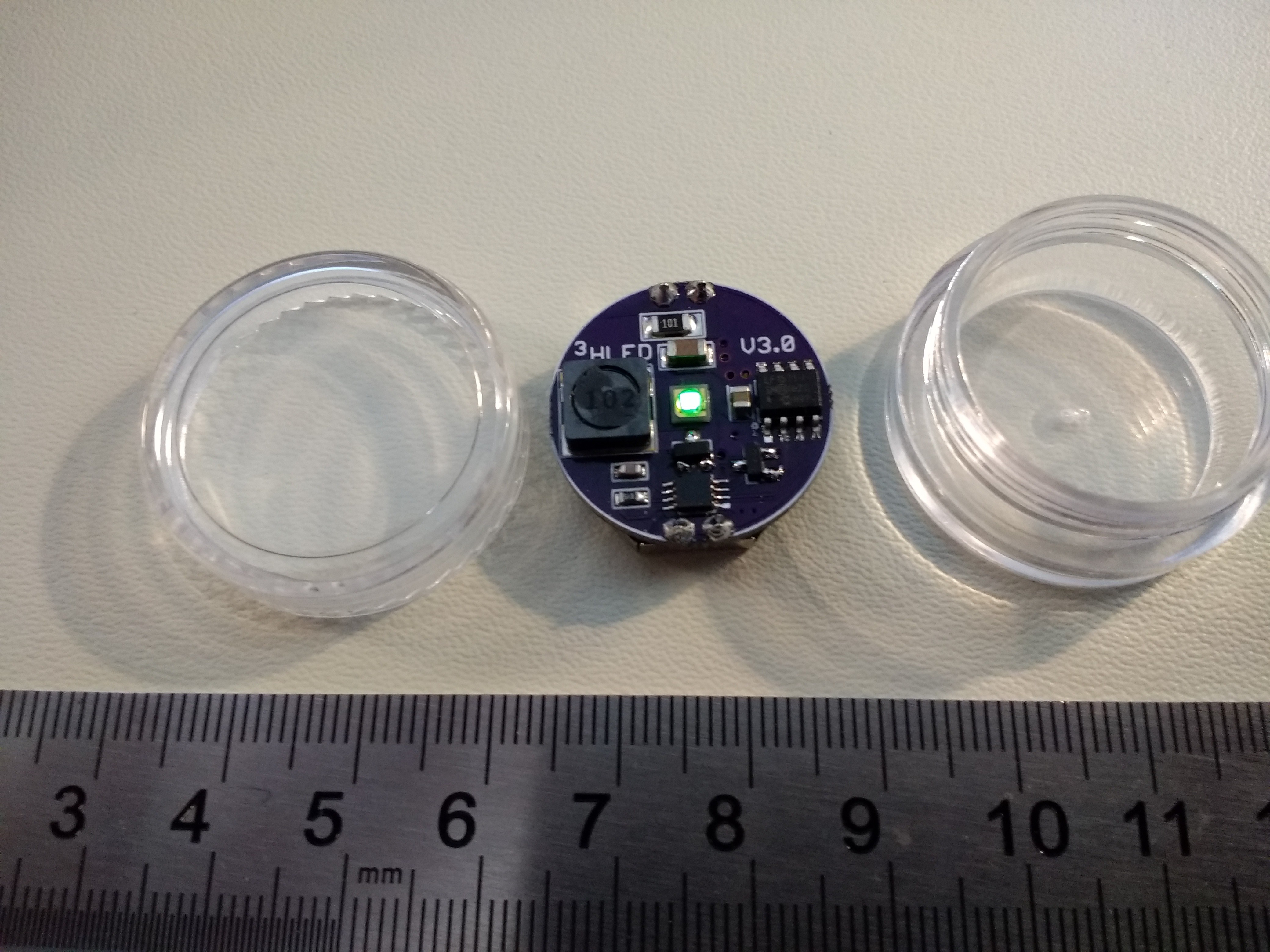 The PCB uses a through-hole CR2032 holder (smaller than the SMT version), allowing it to fit in the jar.
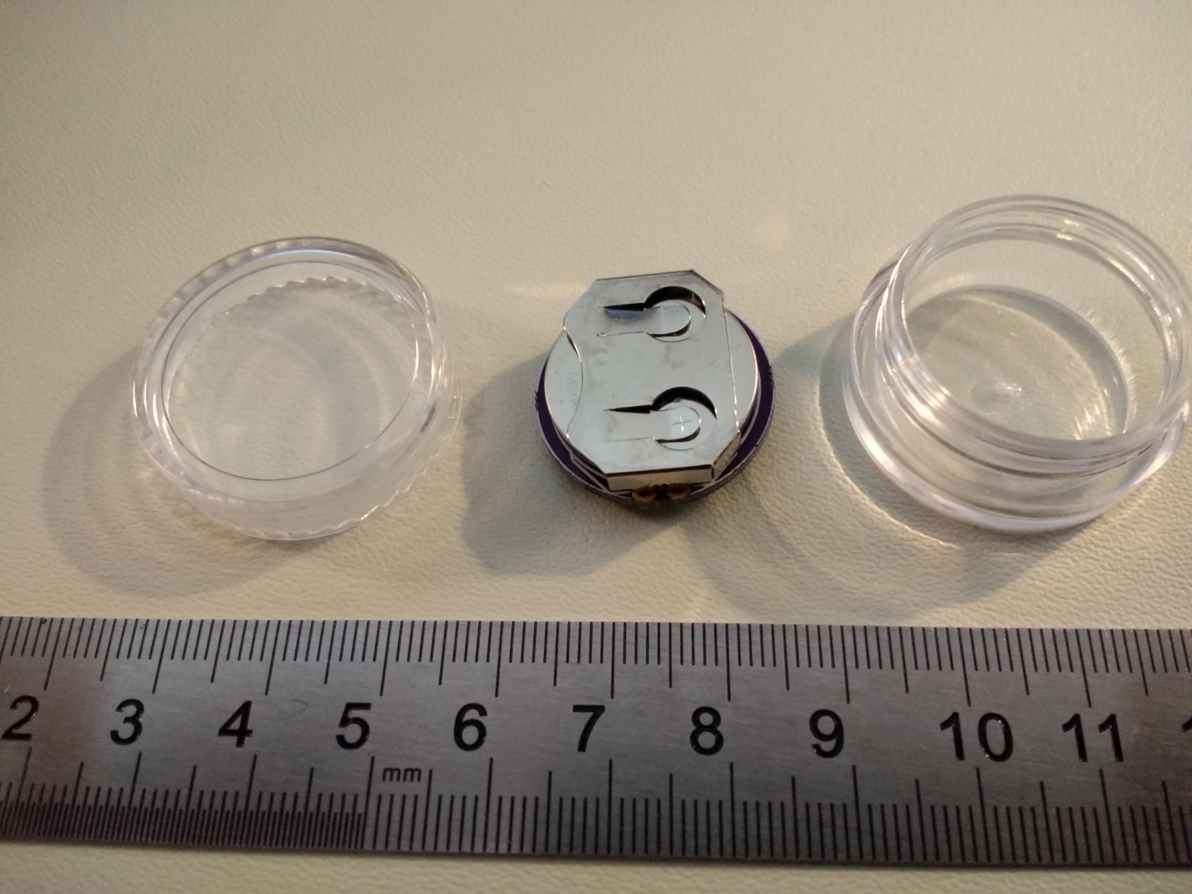
Circuit
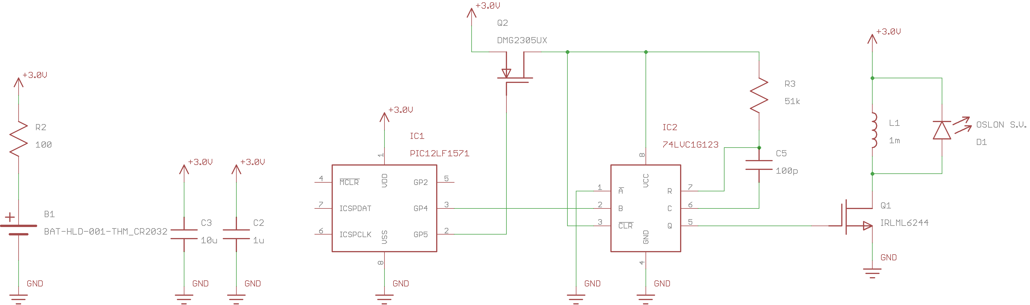
The V3.0 circuit uses a 74LVC1G123 monostable to produce short, accurate pulses for ramping up current through the inductor. The inductor size and monostable pulse width are selected to optimize the drive current to the LED, based on measured LED efficiency vs current. A PIC12LF1571 uses two synchronized PWM outputs to control the pulses. One PWM gates power to the monostable (it consumes too much quiescent power), while the second PWM triggers the pulse. The 16-bit PWMs on the PIC allow very fine tuning of pulse frequency and hence battery lifetime vs LED brightness. Combined with inductor and monostable resistor selection, the circuit lets you tune for very good electrical and LED efficiency while allowing accurately tunable runtime.
Note: a different value of R3 is required for each type of LED.
Bill of Materials
The following components are required for any flavor of V3.0:
- (1) PIC12LF1571 8-SOIC DigiKey part # PIC12LF1571-I/SN-ND $0.58 each
- (1) 74LVC1G123 monostable SM8. DigiKey part # 296-18758-1-ND $0.70 each
- (1) 10uF 25V 1206 X7R MLCC capacitor. DigiKey part # 1276-1804-1-ND $0.26 each
- (1) 1uF 25V 0805 X7R MLCC capacitor. DigiKey part # 1276-6469-1-ND $0.10 each
- (1) 100 ohm 1206 resistor. DigiKey part # 311-100FRCT-ND $0.10 each
- (1) IRLML6244 N-channel SOT23 MOSFET. DigiKey part # IRLML6244TRPBFCT-ND $0.54 each
- (1) DMG2305UX P-channel SOT23 MOSFET. DigiKey part # DMG2305UX-13DICT-ND $0.44 each
- (1) CR2032 Battery retainer. Digikey part # BAT-HLD-001-THM-ND $0.28 each
- (1) 100pf C0G 0603 capacitor. DigiKey part # 311-3599-1-ND $0.11 each
- (1) "5g" polystyrene jar. Buy from Amazon $7.99/50, ebay or elsewhere
- (1) CR2032 cell. DigiKey part # P189-ND $0.29 each
Depending on the LED you choose, you will need a different PCB, resistor, and possibly inductor. Choose from one of the LEDs in the following sections:
OSLON Signal Verde (505nm)
This LED has the best optical match to dark-adapted eyes. If you are just going to build one version, use this LED, and forget about the $3.49 price tag. It requires a 1mH inductor and 51k resistor for optimum efficiency.
- (1) OSLON Signal Verde (505nm) LED. DigiKey part # 475-3450-1-ND $3.49 each
- (1) Bourns SRR6028-102Y 1mH inductor DigiKey part # SRR6028-102YCT-ND $0.74 each
- (1) 51k 0603 1% resistor. DigiKey part # 311-51.0KHRCT-ND $0.10 each
- (1) PCB. Order from OSH Park. $4.10 for 3.
Luxeon C Cyan
This LED is my second choice for dark-adapted eyes. It's cheaper than the OSLON at $2.74, but just a little too blue for optimum visibility. The higher optimal current also makes it flash more visibly at extended run-times (see below).
- (1) Luxeon C Cyan LED. DigiKey part # 1416-1917-1-ND. $2.74 each.
- (1) Bourns SRR6028-102Y 1mH inductor DigiKey part # SRR6028-102YCT-ND $0.74 each
- (1) 75k 0603 1% resistor. DigiKey part # 311-75.0KHRCT-ND $0.10 each
- (1) PCB. Order from OSH Park. $4.10 for 3.
Especially with this LED, you may want to choose a different inductor/resistor combination if you want extended run-times with minimal flickering. See the section on alternate inductors below.
Cree XPE2 Green
This is an economical alternative to the above LEDs. The 525nm emission wavelength is a good trade-off for medium light viewing conditions, being in-between the 507nm and 555nm sensitivity peaks of the human eye. It's a bargain, too: even opting for the brightest bin available at DigiKey, you'll only pay $1.86.
- (1) Cree XPE2 Green (525nm) LED. DigiKey part #XPEBGR-L1-0000-00F02CT-ND. $1.86 each
- (1) Bourns SRR6028-102Y 1mH inductor DigiKey part # SRR6028-102YCT-ND $0.74 each
- (1) 59k 0603 1% resistor. DigiKey part # 311-59.0KHRCT-ND $0.10 each
- (1) PCB. Order from OSH Park. $4.10 for 3.
If you're ordering parts, get the 59k resistor. If you only have a stock of E24 series resistors, you can substitute a 56k or 62k.
Be careful mounting this LED. I had to do some skillet-rework on my first one. The mark is on the anode side, unlike any other diode ever created. I realize the good people at Cree are special snowflakes who should get to do it any way they like, but they should put the f'ing mark on the cathode like everyone else.
Assembly Instructions
None of the LED choices can be hand-soldered, so you'll have to reflow the board. All of the components except the through-hole battery holder can be mounted on the top, then the holder hand-soldered. Consult the parts placement diagram below.
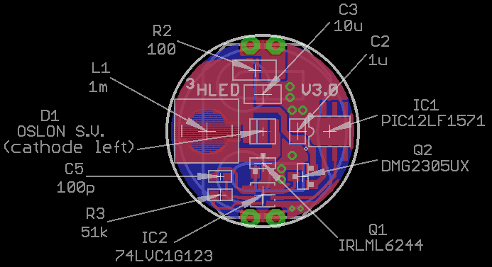
Pay special attention to the MOSFETs - I mixed them up on my first board, and had to swap them with a soldering iron. The other likely sources of confusion are mixing up the 0603 R's and C's (I had to check twice), and mis-orienting the LED (cathode goes left). Also note that there is a different value of R3 for each LED.
Software
Fixed-runtime Assembly Code
This version uses a hard-coded pulse frequency, so the brightness and battery life are fixed when you download the code. The assembly source for the code is in the GitHub repo. I also checked in a hex file, but it's probably not very useful. Due to component tolerances, each PCB requires tuning to achieve a specified battery lifetime (you didn't have this option with earlier versions). There is a single parameter in the code controlling the brightness/lifetime trade-off:
;;;
;;; adjustable pulse frequency parameter
;;;
FREQ            equ .157
The FREQ parameter controls the LED pulse frequency. In the case of the first OSLON Signal PCB, I found that a frequency of 157 Hz produced a current drain of 12.5uA, equivalent to a 2-year run-time for a CR2032.
The plots in the next section "Tuning Parameters" should be used to get initial estimates of the pulse frequencies required to achieve a specified run-time. After that, some trial-and-error tuning is required.
I'm working on an automatic tuning script that uses a PICkit3 and serial-enabled DMM to measure the current drain and determine the correct frequency for a given run-time.
Programmable-runtime C-Code
This version allows you to set the runtime when you first insert the CR2032. The runtime is adjustable from 1 year to 10 years: the LED blinks out the runtime in years (5 blinks = 5 years, etc). After blinking out the runtime 10 times, the code enters the normal glow mode, and the brightness/current consumption is fixed until you remove the battery. The code is documented in a separate log, and is available in the GitHub repo.
For the V3.0 PCB, you need to short pins 4 and 8 on the PIC12LF1571 to change the runtime. A V3.1 PCB will include a tiny switch for this purpose.
Tuning Parameters
The following plot is an estimate of the pulse frequency required to achieve various run-times from a CR2032 for the OSLON Signal Verde LED.
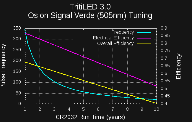
These numbers are estimated based on simulations, but seem fairly close - certainly good enough to begin fine-tuning. For example, I determined a frequency of 157 Hz on the first board for a 2-year run-time (12.5uA), which agrees with the plot quite well. Also shown on the plot are the electrical efficiency (magenta) and "overall" efficiency. The latter is a combination of the electrical efficiency and how well the circuit matches the optimum LED drive current. In both cases, you can see how the efficiency drops as run-time is increased. This is due to a fixed overhead for running the PIC PWMs. You can also see that for long run-times, the pulse frequency becomes low enough to flicker visibly. At 10-years, this LED is pulsing at 20Hz, which is quite visible. If you arbitrarily take 50Hz as the flicker threshold, you can set this version to run as long as 5.5 years with no flickering.
Here's the same plot for the Cree XPE2 525nm LED:

I haven't verified this curve with the PCB yet - I'll delete this sentence when I do.
This LED requires a slightly higher current for best efficiency, so there is more energy per pulse. The net result is a lower pulse frequency for a given current drain. So, this LED will begin to flash visibly at shorter lifetimes than the OSLON LED. The difference isn't huge, though. At a 10 year life, this LED is flashing at 15Hz, still very visible, but not that much different from the OSLON. Again using an arbitrary 50Hz flicker threshold, this version can be set to a maximum 4.5 year run-time before flicker becomes visible.
The Luxeon C LED is a little different. The efficiency peak for this LED is at a higher current, meaning longer pulse times or smaller inductors for best efficiency. Here's the chart using a 1mH inductor (and 75k resistor):
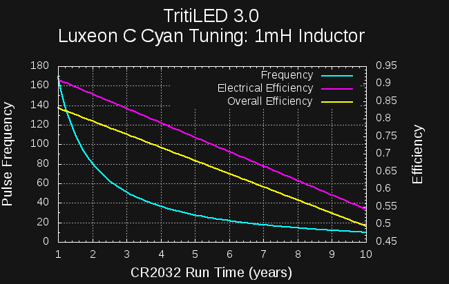
The efficiency is very good, but due to the higher energy-per-pulse, you need to use low frequencies to get extended run-times. For example, using the 50Hz criteria, you can only extend run-time to about 3 years before the LEDs flickering becomes noticeable.
If, on the other hand, you use a smaller 100uH inductor (and 15k resistor), you get the following:
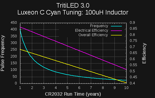
Now, each pulse is much shorter (1.9us), so dumps less energy into the LED, and the frequency for a given run-time is higher. You can extend the run time to 6 years before hitting the 50Hz threshold. The penalty is reduced overall efficiency (compare the two yellow lines), since the LED isn't driven as close to its optimal current.
Alternate Inductors
There is a trade-off between efficiency and flickering at extended run-times for this circuit. Smaller inductors produce pulses of less energy, so a higher frequency can be used at a given current drain. Unfortunately, as the inductor is reduced, the overhead of the rest of the circuit is larger in comparison, which reduces the overall efficiency. I've prepared the following tables for those who might want to make extended-run-time versions with minimal flicker, and are willing to sacrifice some efficiency to do so. In each table, the recommended values are in bold.
The tables list the inductor (L1) value, the resistor (R3) value, the runtime at which the pulse frequency drops below 50Hz, and a figure-of-merit efficiency relative to the best you could possibly do from coin cell to light with the given LED. The figure-of-merit is calculated for a 2-year run-time.
Note that figure-of-merit efficiencies in the tables are relative: you can't make comparisons directly between the different LEDs, since I don't have a calibrated way to measure the light output.
OSLON Signal Verde (505nm)
| Inductor | R3 | 50Hz Threshold (yrs) | 2yr FOM |
| 100uH | 13k | 7.7 | 50% |
| 220uH | 20k | 6.8 | 55% |
| 470uH | 33k | 6.2 | 60% |
| 680uH | 39k | 5.9 | 62% |
| 1mH | 51k | 5.5 | 65% |
Luxeon C Cyan
| Inductor | R3 | 50Hz Threshold (yrs) | 2yr FOM |
| 100uH | 15k | 6.2 | 65% |
| 220uH | 24k | 5.2 | 71% |
| 470uH | 43k | 4.0 | 75% |
| 680uH | 56k | 3.6 | 77% |
| 1mH | 75k | 3.0 | 79% |
Cree XPE2 Green (525nm)
| Inductor | R3 | 50Hz Threshold (yrs) | 2yr FOM |
| 100uH | 12k | 7.6 | 56% |
| 220uH | 20k | 6.5 | 62% |
| 470uH | 36k | 5.4 | 68% |
| 680uH | 47k | 4.9 | 70% |
| 1mH | 59k | 4.4 | 73% |
TBD
I will continue to update this log as I build and tune various flavors of V3.0. If you find anything confusing, missing, or suspect an error, please let me know.
Discussions
Become a Hackaday.io Member
Create an account to leave a comment. Already have an account? Log In.
Great project! I notice Q1 symbol is a pfet, it needs to be a nfet to work.
Are you sure? yes | no