 Ted Yapo
First a quick note: I've re-thought my earlier log about ENIG finish. Instead of spreading fear, uncertainty, and doubt about this noble metal finish, I've decided to take a more scientific approach. I'll have my boards fabbed in HASL and ENIG, and see if I can detect any differences in performance.
You Broke My Printer
I really don't want to hear this - ideally because it didn't happen :-) I really don't want to break my printer(s), either. I've developed three lines of defense against damaging expensive printers by using them as scanning magnetometers: kill switches, sacrificial scanning heads, and a safety-conscious scanning protocol enforced in software.
Robot Kill Switches
I'm a firm believer in hardware kill switches. Right at the power source. No matter what coders would have you believe, no software-based kill switch is reliable enough to adequately protect life and property. This is especially true with machines built around current 3D printer controllers, whose firmware buffers up commands to accelerate printing. Sending a "stop" command just doesn't cut it when your printer is breaking itself. I've tried.
Here's a picture of the switches I use for 3D printers and other devices in the shop:

The first two are simple off-the shelf devices - a power strip and a wired remote switch. The latter is convenient because it lets you keep the switch easily reachable, but the only one I could find is 2-wire, meaning you have to lift the ground connection to use it, which is not ideal. Unable to find a suitable wired switch commercially, I built the third model from an extension cord (cut in half), a heavy-duty outdoor enclosure, and a paddle switch. The large paddle is convenient because you can hit it with your hand or foot or whatever isn't being pulled into the machine at the moment.
If you end up using the scanner being designed here, I highly recommend using a hardware kill switch of some sort. Just in case.
Head Mount Design
The idea for this project is to avoid any permanent modifications to your printer. While I'm also looking into making a dedicated scanning platform based on printer designs, for now, the focus is on adapting existing printers. In order to protect the printer during scanning, I envisioned a scanning head design combining a spring and shear-pin that would yield if struck gently, but break long before the printer if struck hard. Here are some steps along the evolution of the scanning head design:
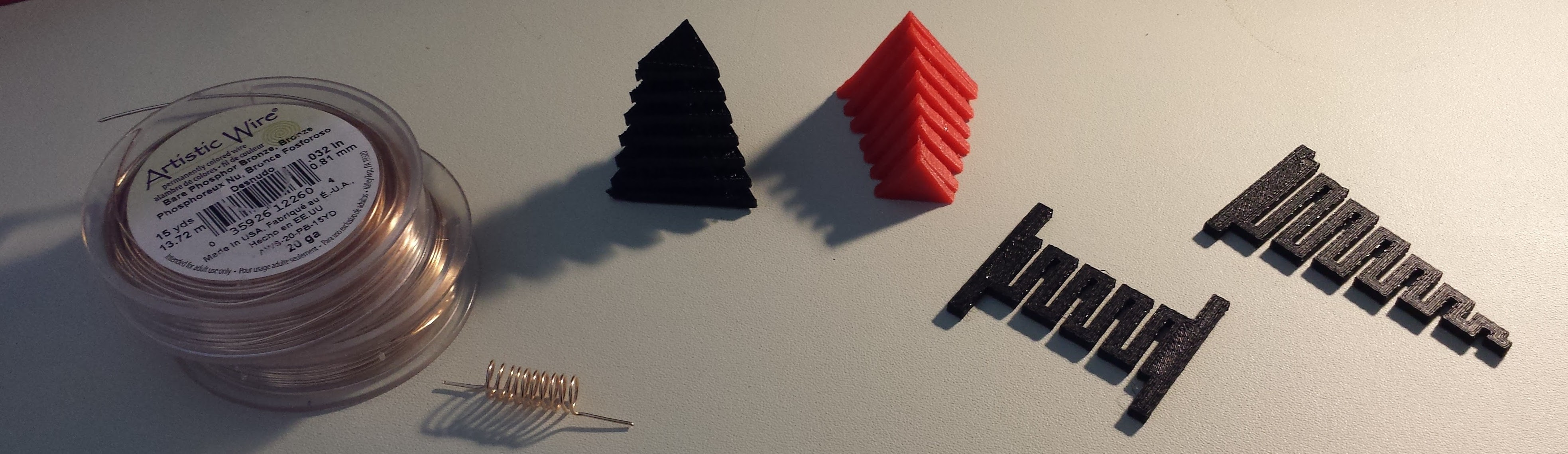
Wanting to avoid ferrous metals in the head design, I started with springs wound of phosphor-bronze wire - the idea was to connect two lengths of wooden dowel with the springs. I soon remembered that using a 3D printer as a scanning magnetometer pre-supposes that the user has a 3D printer (duh!), so a printed design would be ideal. My first experiments with the triangular "3D" springs shown were both interesting and frustrating. Making the springs triangular in cross-section makes them easily printed without support material, but unfortunately, the "weak direction" of the print always ends up along two of the sides, making them too fragile to be useful in this design. I'll post the OpenSCAD file for them anyway, in case somebody can find a way to improve the idea. I finally settled on a flat spring design like the last two - this design keeps the spring in the "strong" printing direction, has a low profile, and prints quickly (good for a sacrificial part). The spring constant and breaking point are both easily changed (but not directly calibrated) by manipulating the shape. My daughter called the tapered version a "tornado spring" - this is the design I ended up using.
My ultimate goal is to come up with a universal mount for attaching the scanning head to any 3D printer. For now, I've settled on simply mounting it on my first test printer - a Solidoodle 3. Here's the design I'm currently testing:
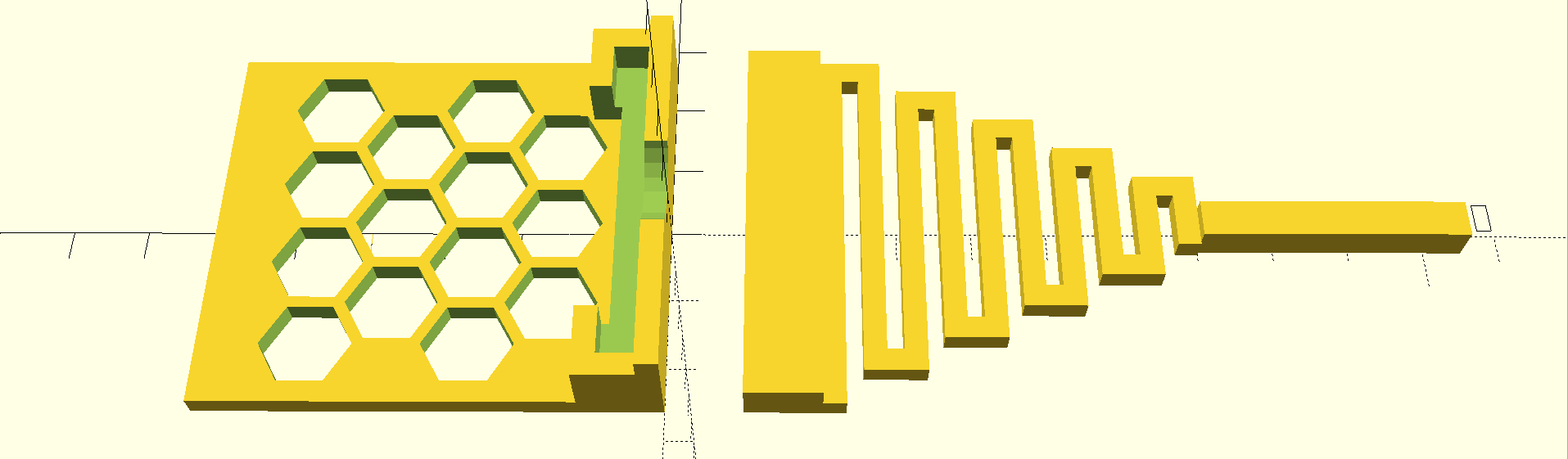
The Solidoodle head has a laser-cut piece of plywood that makes a convenient attachment point; this mount is press-fit onto that board, then held in place with a piece of adhesive tape. The hexagonal grid is just lightening holes to reduce material used and printing time. The two pieces are designed to be glued together in this first iteration. Since the spring sensor mount also functions as a shear pin and is designed to break, a quick-release mount of some sort will eventually be required. A quick-release probe mount also figures largely in the scanning protocol discussed below.
Here's the design mounted on the printer head, along with the mount for the (huge!) MLX90393 evaluation board:
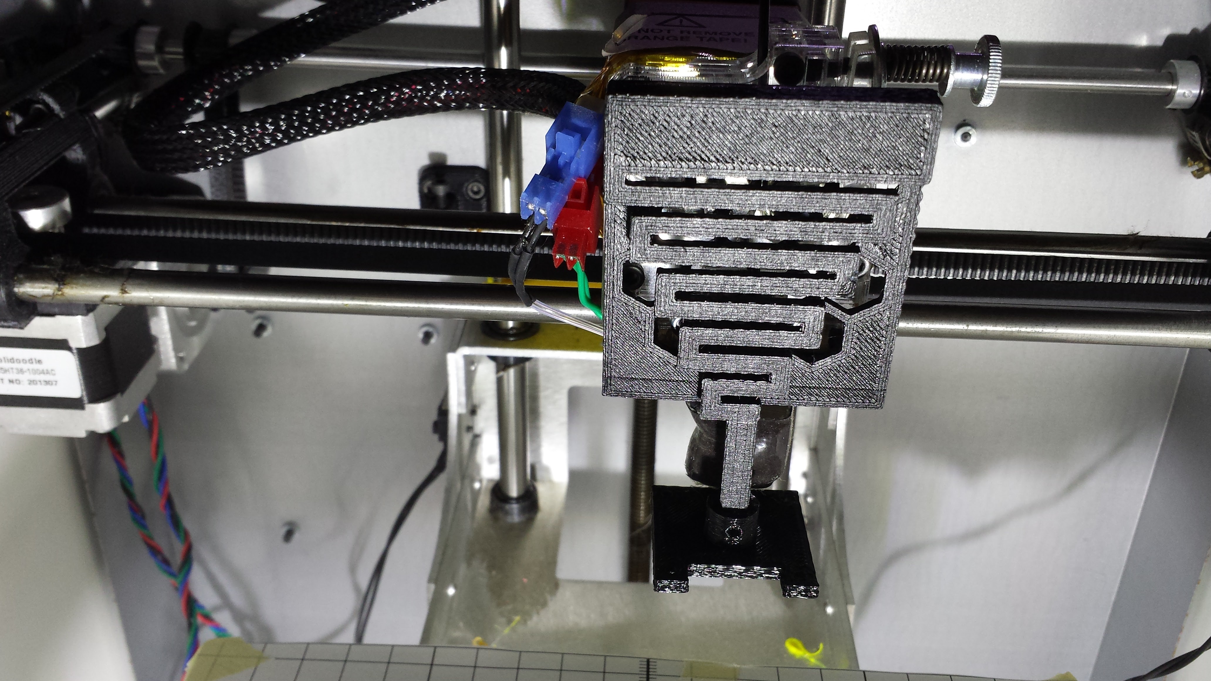
This head is designed for "Phase 1" of the design, where all scanning takes place above any target object - so clearance to the printer's hotend is not an issue. In latter phases, when scanning inside the bounding volume of targets, the probe will be extended below the nozzle with a longer spring assembly. Even in this version, the scanning head should be a bit lower to provide some extra clearance for the nozzle.
Scanning Protocol
Additive manufacturing robots have an easy time of path planning: they inhabit an empty universe. As soon as a layer is printed, the tool head moves up relative to the work-piece, thus never having to concern itself with avoiding contact with the piece. Subtractive manufacturing robots don't have it so good: there's often a big piece of metal in the center of their world that they must avoid while moving. This is the same problem that will be faced in Phase 2 and beyond of the scanner: path planning algorithms will be required to keep to the scanning head (and printer head itself) from striking the target.
I'm still thinking about the path planning problem, but I've come up with a preliminary scanning protocol to avoid the most obvious causes of object collisions in the scanner, while avoiding modification of the limit switches and other mechanisms of the printer. Here's the step-by-step, starting from the beginning of a scan:
- User enters scan parameters, including bounding volume or 3D model of scanning target
- User is prompted to remove the quick-release detachable probe from the printer, and any scanning target currently on bed
- User acknowledges completion of this task
- Printer homes head (as usual), then moves head to center (x, y) of scan volume, at z-level safely above scanning volume
- User is prompted to mount quick-release probe and arrange scanning target on bed
- User acknowledges completion of this task
- Printer scans over volume, using path planning algorithms to avoid striking target with probe
- When scan is done, printer moves head to original centered position above the target and prompts user to remove target
- User acknowledges completion of this task
- If a baseline scan is desired for calibration, printer performs this baseline scan, then returns to center position
- User is prompted to remove quick-release probe
- User acknowledges completion of this task
- Scan is complete
It sounds like a lot of steps, but they're all common-sense and fairly trivial. Some obviously could be eliminated if a dedicated scanning device were used instead of leveraging an existing printer.
In all the "user acknowledgement" steps, I'm considering using a trivial CAPTCHA-type response like:
Enter "576" to continue:where the "576" is randomly generated. The idea is to prevent accidental acknowledgements from distracted operators (or cats walking on your keyboard). You'll be able to turn this off.
Next Up
I'm continuing tests on the MLX90393 - I've wound a Helmholtz coil (actually two!), worked out some math, and checked the calibration of my current meter to get to the bottom of the scaling issues. I'll report progress soon. I'm also working on two board designs for the probe head, and of course, getting a Phase 1 software release ready.
Discussions
Become a Hackaday.io Member
Create an account to leave a comment. Already have an account? Log In.
Thanks again for your work and detailed documentation!
I am interessted how the calibration (in detail) works out for you...
Are you sure? yes | no
Thanks for your comment and support! I took apart the first pass hacked demo code, and have it put back together into a semi-usable state now, so I can make some scans see what fields lurk inside the empty printer, and how repeatable they are.
Are you sure? yes | no