0%
0%
Quick Sample Player
My little sister needs a sample player for a show in just a couple of days. Can I make it happen?
 T. B. Trzepacz
Become a Hackaday.io member
Already have an account? Log in.
Just one more thing
To make the experience fit your profile, pick a username and tell us what interests you.
Pick an awesome username
hackaday.io/
Your profile's URL: hackaday.io/username. Max 25 alphanumeric characters.
Pick a few interests
Projects that share your interests
People that share your interests


 I took some scrap that we had salvaged from the bend tests for Twister to build our case in. But it needed some holes for buttons and screen and mounting, so I designed a template in Solidworks. This was done extremely quickly... show is the next day!
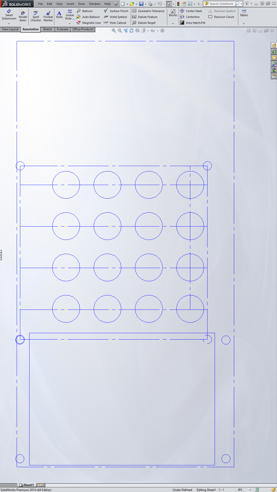
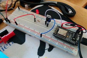
 We also need some holes for the audio jack and USB port, so I drilled those in the side with a drill press and a step drill. I learned my lesson from earlier times... the step drill is the only way to drill acrylic.


 It seems like I had even more trouble despite my efforts. The holes were too close to the edge of the case for decent mounting...


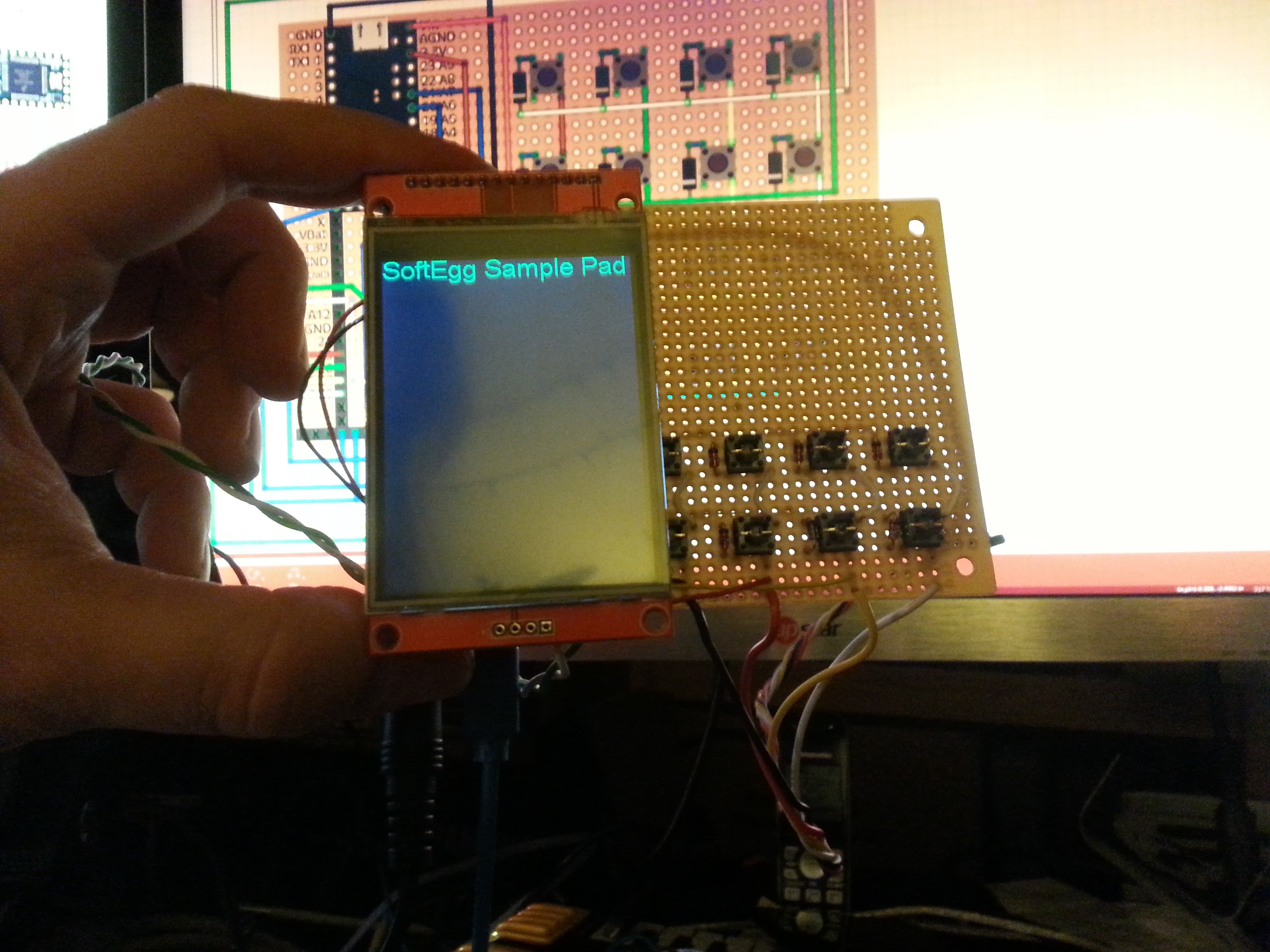
 Oh, that is just the touch sensitivity going bonkers at this crazy pressure on the right side... I have code in to let you draw on the screen to test the touch stuff...
 Then...
 It had never been tested, but no time like the present, right.


 WJCarpenter
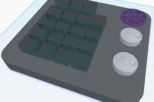
 mrpendent
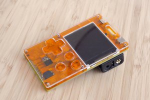
 deʃhipu
Hey Tim, I really like this project!
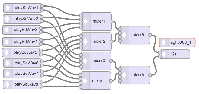
I know this is an old one, but I was wondering if you could share oyu experiences using the Teensy to play samples... I've got a project I'm working on that I'd like to be able to trigger multiple wav/mp3 files at once for a drum sampler, using analog inputs from Roland drum pads in place of buttons. I've had reasonable success using an Arduino Mega to read the buttons and four dfrobot mp3 shields (one for each pad) to handle sounds with the outputs all mixed into one output, but I would love to reduce the number of boards for reliability.