 will.stevens
The relays used in this project use electromagnets made by coiling enameled copper wire around an iron nail. How many turns of wire should be used? What voltage should be used?
There are several factors to consider. From theory, the magnetic field strength inside the coil is proportional to both the number of turns and the current. For a fixed voltage, if the number of turns doubles, the current halves because the resistance doubles, and so the magnetic field strengh should stay the same. Because the power consumed is inversely proportional to the resistance, the power consumed halves. This favours a larger number of turns. Because the power consumed by the coil is proportional to the square of the voltage, ideally we should try to have a low voltage and a large number of turns.
In practice, a large number of turns takes up space, and the diameter of the coil gradually increases as the number of turns increases. Eventually a point of diminishing returns is reached, where increasing the number of turns decreases the efficiency of the electromagnet.
An issue related to the power consumption of the electromagnet is the temperature of the coil. Since electromagnets in the project will be mounted in PLA, we don't want the temperature of the electromagnet to exceed the glass transition temperature of PLA - about 60-65 C.
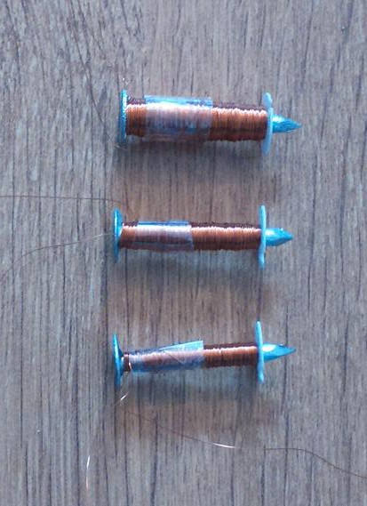
I made three electromagnets, one with 430 turns of wire, one with 860 turns of wire, and one with 1720 turns of wire (they were wound with the assistance of a hand drill, and these numbers correspond to 100,200 and 400 turns of the drill handle respectively). The nails are 30mm galvanized iron clout nails (the shiny kind, not the dull kind) with a diameter of 3.1mm. For these experiments, 24mm of the nail was wrapped with 40 swg enameled copper wire. See photo:
The following setup was used to measure the relative strength of each electromagnet:
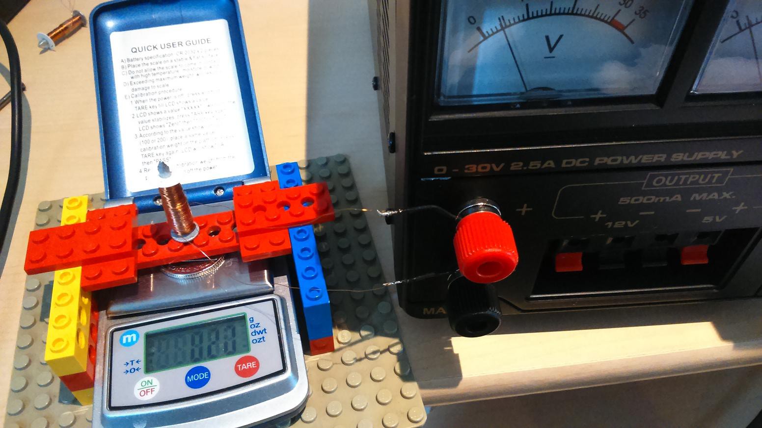
When power was applied to the electromagnet under test, the scale showed a reduction in weight of the coin on the pan. The reading from the scale was taken within a few seconds after power on. The reading gradually reduced over time because the coil heated up, increasing the resistance.
The table below shows the force exerted on the coin by each electromagnet.
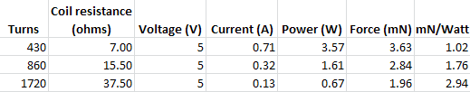
You can see that the resistance of the 1720 turn coil is more than four times that of the 430 turn coil - 5.4 times larger - because the diameter of the coil is larger on the outside than on the inside. But it doesn't look as though the 1720 turn coil has reached the point of diminishing returns yet.
A thermocouple was used to measure the temperature of the electromagnets. By holding the thermocouple in various places, I found that the place with the highest temperature was the centre of the head end of the nail. The room temperature was 20 C, the electromagnets were laid horizontally on a wooden tabletop.
The 430 turn electromagnet reached 90 C after one minute, and the temperature was still increasing.
The 860 turn electromagnet reached 80C after 3 minutes, and the temperature was still increasing.
The 1720 turn electromagnet reached 53 C after 7 min, and the temperature seemed to have reached a steady state.
From these experiments, it seems that at 5V, anything much less than 1720 turns would get too hot (although in an active circuit, relays would probably have a duty cycle of about 50%, so the temperature wouldn't get as high as in this experiment). The number of turns hasn't yet reached the point of diminishing returns on efficiency. I have been able to make relays using electromagnets with 1720 turns of wire that will operate at 4V or greater. I used 40 swg copper wire because it is what I happened to have on my shelf. It seems worth exploring wire with a larger diameter - this might permit a lower voltage to be used, and reduce the power consumption.
Discussions
Become a Hackaday.io Member
Create an account to leave a comment. Already have an account? Log In.