 will.stevens
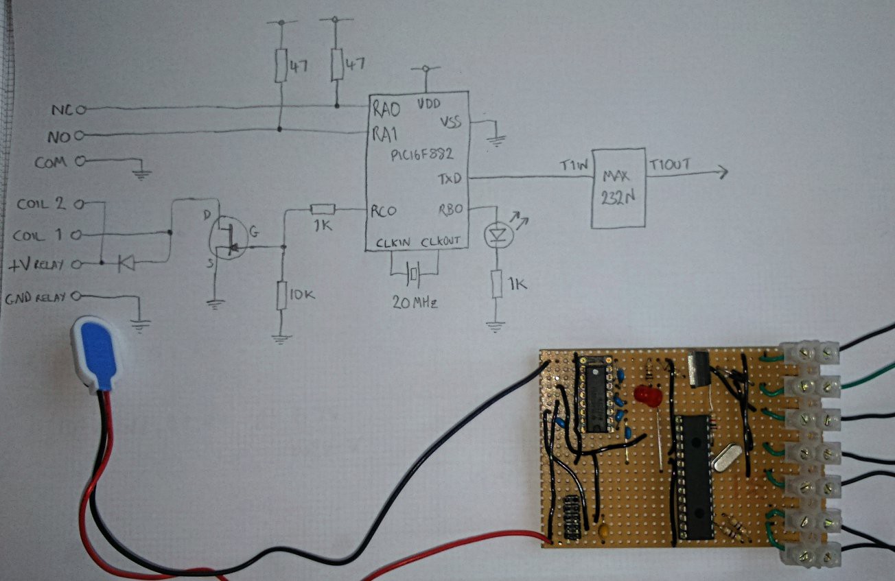
This circuit is used to measure how long it takes a relay to switch, and also to monitor the resistance of the relay contacts when closed. This is needed in order to assess and compare different DIY relay designs. Before making this I had been measuring relay timing using the digital IOs on a Raspberry PI. This has two problems: occasionally OS task switching interferes with timing measurement, and it doesn't monitor relay contact resistance. (Making a poor contact is a common relay failure mode).
The circuit is controlled by a PIC16F882 microcontroller. The PIC firmware toggles RC0 to switch the relay coil on or off, then continuously measures the voltage on either RA0 or RA1 depending on whether the coil is off or on respectively. Each of the relay contacts forms a voltage divider with one of the 47 ohm resistors connected to RA0 and RA1. The voltage measurement is sent to the RS232 interface at a rate of one measurement every 177 microseconds - about 5650 measurements per second. The LED in the circuit is simply an 'I am alive' indicator - it blinks twice when the circuit is powered on, but does nothing else.
The analogue-to-digital converter (ADC) in the PIC16F882 has a resolution of 10 bits. When the result is sent to the RS232 interface, this is split into two bytes. The first byte transmitted has the most signficant bit (bit 7) cleared, and the lower 7 bits are the lower 7 bits of the 10 bit ADC result. The second byte transmitted has the most significant bit set, and the lower 3 bits are the upper 3 bits of the ADC result. Therefore the laptop that collects the byte stream sent by the PIC can tell which byte is which by testing the most significant bit. The byte stream is turned into a CSV file.
The PIC source code (developed using MPLAB V8.76) can be found in relaytest/adc.asm in the relayreprap github repository.
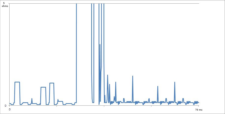
The graph above shows measurements from an OMRON G5LA-1 12V SPDT relay. At the start of this graph, the relay coil is on and the Normally Open (NO) contact is being monitored. The resistance of the NO contact is usually very low - between 50 and 100 milliohms. This is at the limit of what the circuit can measure. Just to the left of the centre of the X-axis the PIC turns the relay coil off and starts monitoring the resistance of the Normally Closed (NC) contact. Initially the contact is open and so the resistance goes off the top of the graph. After 5 milliseconds the contact closes, bounces for about 5 milliseconds and then remains closed. When closed, the reading from the ADC normally corresponds to a contact resistance of around 150 milliohms. When the relay coil switches on again (not shown on the graph), it takes about 4 milliseconds for the NO contact to close, with very little bouncing. Both the time and contact resistance are consistent with the relay specifications.
Sometimes the contact resistance appears to spike to a higher value - upto about 1 ohm. It's possible that this is noise rather than a real effect at the contact.
Discussions
Become a Hackaday.io Member
Create an account to leave a comment. Already have an account? Log In.