 Yiğit Topcu
urrent sensor provides an analog output of 0-5v; it can measure both positive and negative current. Therefore, when there is no load, sensor outputs 2.5v.
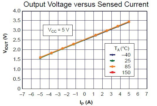
Before I start to build the electronics and the enclosure, I have to check the sensitivity of the current sensor.
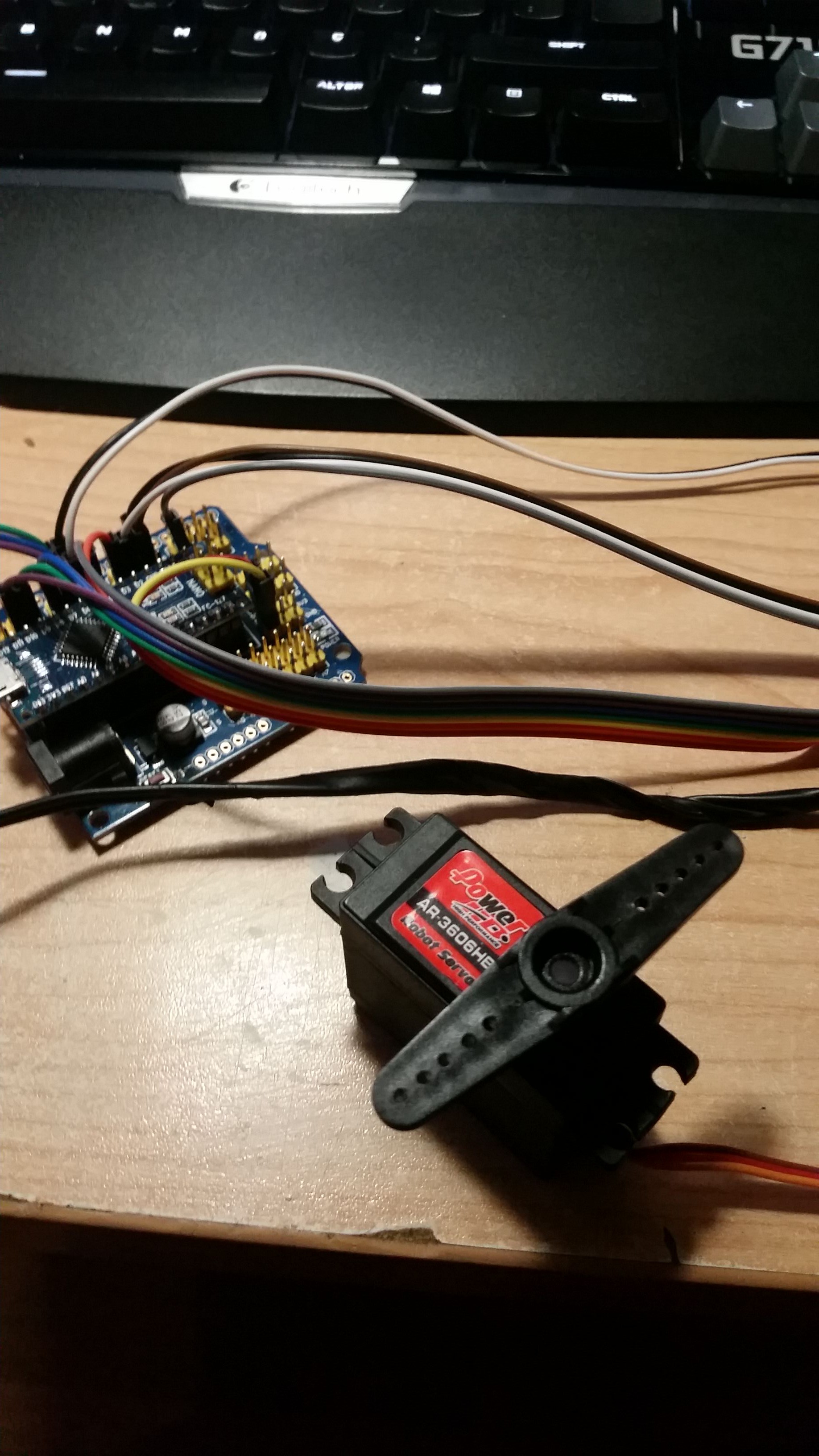
Arduino has 5v ADC but ESP8266 works with 3.3v. I could build a simple voltage divider to lower the sensor output voltage but instead of that I connected sensor output in reverse polarity. Because servo always draw positive current, sensor output will never reach 2.5v. So when the servo is drawing current, I read a lower voltage from the ADC.
I wrote a simple sketch to output analog value using Web Socket connection. With an help of small JavaScript library, I managed to output analog value as graph.
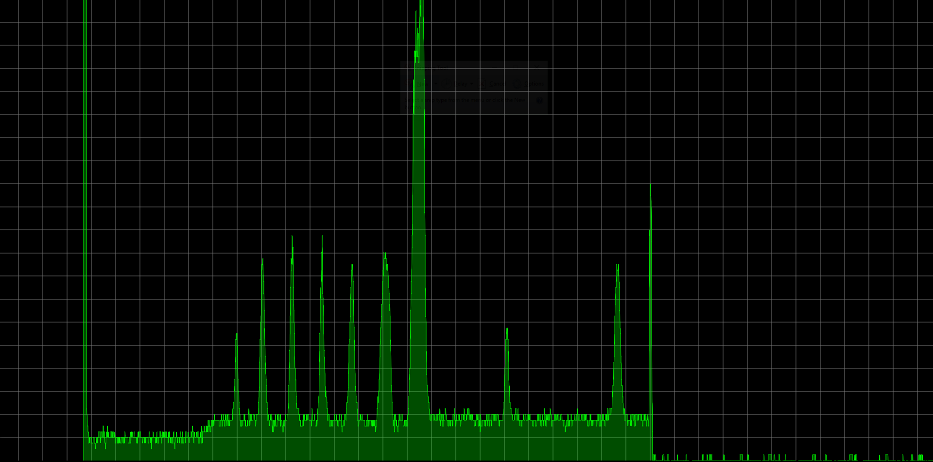
Actually sensor is pretty accurate but there was too much noise on the analog input. It's impossible to determine a threshold point without using a smoothing algorithm.
const int numReadings = 10;
int readings[numReadings];
int readIndex = 0;
int total = 0;

int inputPin = A0;

int smoothValue() {
	total = total - readings[readIndex];
	readings[readIndex] = analogRead(inputPin);
	total = total + readings[readIndex];
	readIndex = readIndex + 1;
	if (readIndex >= numReadings) {
		readIndex = 0;
	}
	return total / numReadings;
}
You can find rest of the code at my GitHub repository.
Discussions
Become a Hackaday.io Member
Create an account to leave a comment. Already have an account? Log In.