 Yiğit Topcu
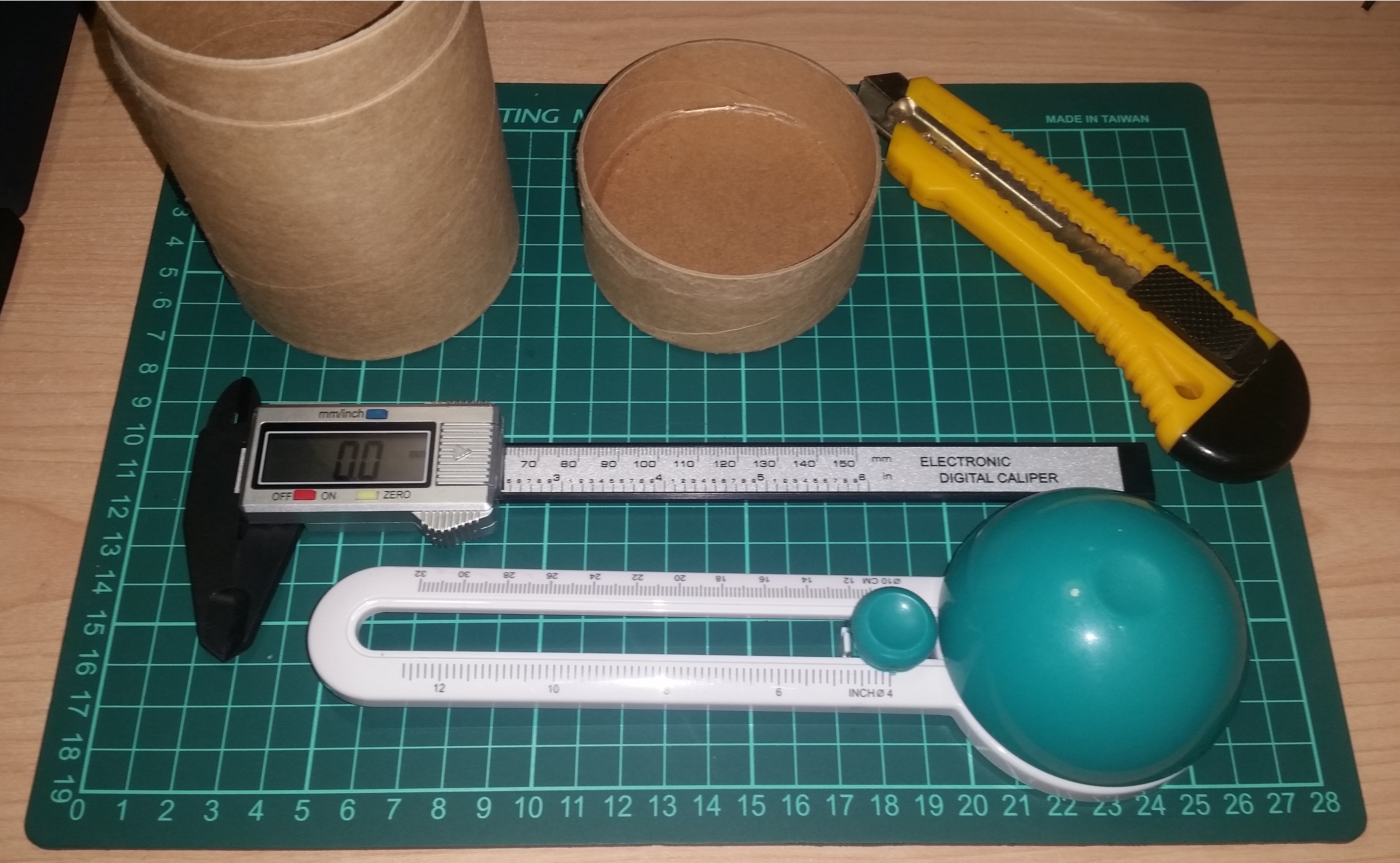
I've already made a decision to the building material while I was testing the servo on my second project log. Cardboard is the easiest material to work on. I can use household tools to cut and shape the material. The only custom tool that I need is circular cutting tool.
The Design
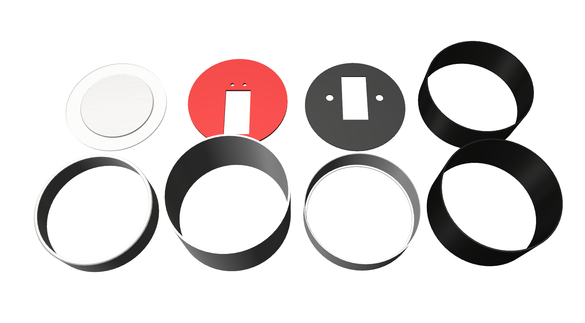
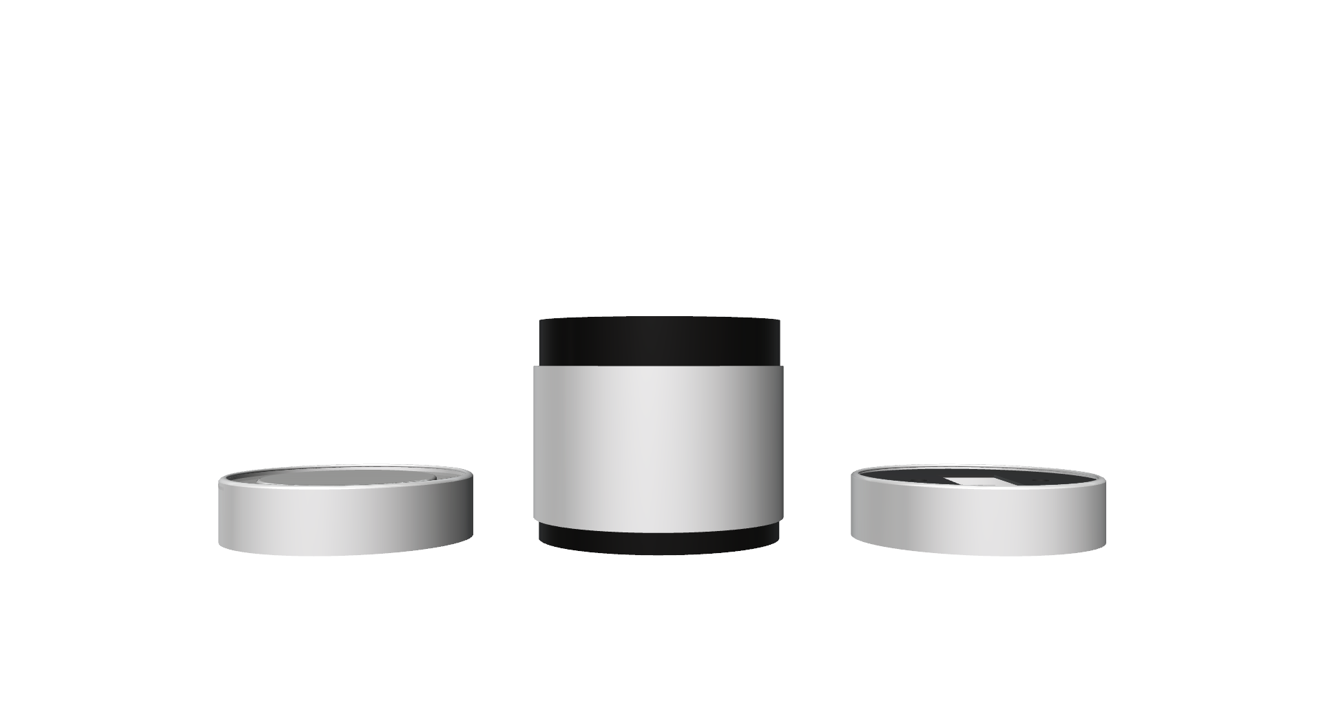
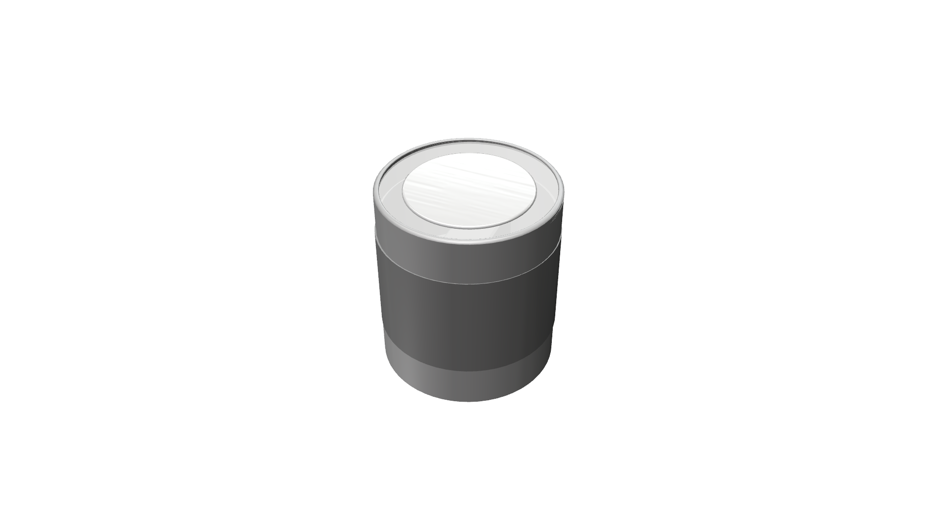
Enclosure must be a close box and there mustn't be any visible cables on the servo itself. I designed the enclosure with 9 unique parts. And Its about 790mm x 960mm.
- Diffuser
- Top Cap
- Middle outer cylinder
- Top inner cylinder
- Servo holder ring
- Bottom inner cylinder
- Bottom cap
- Door mount disk
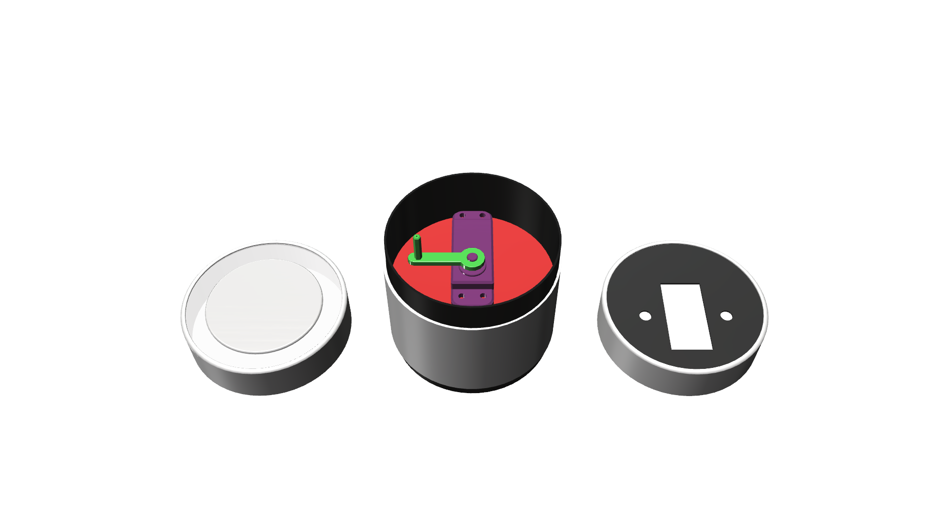
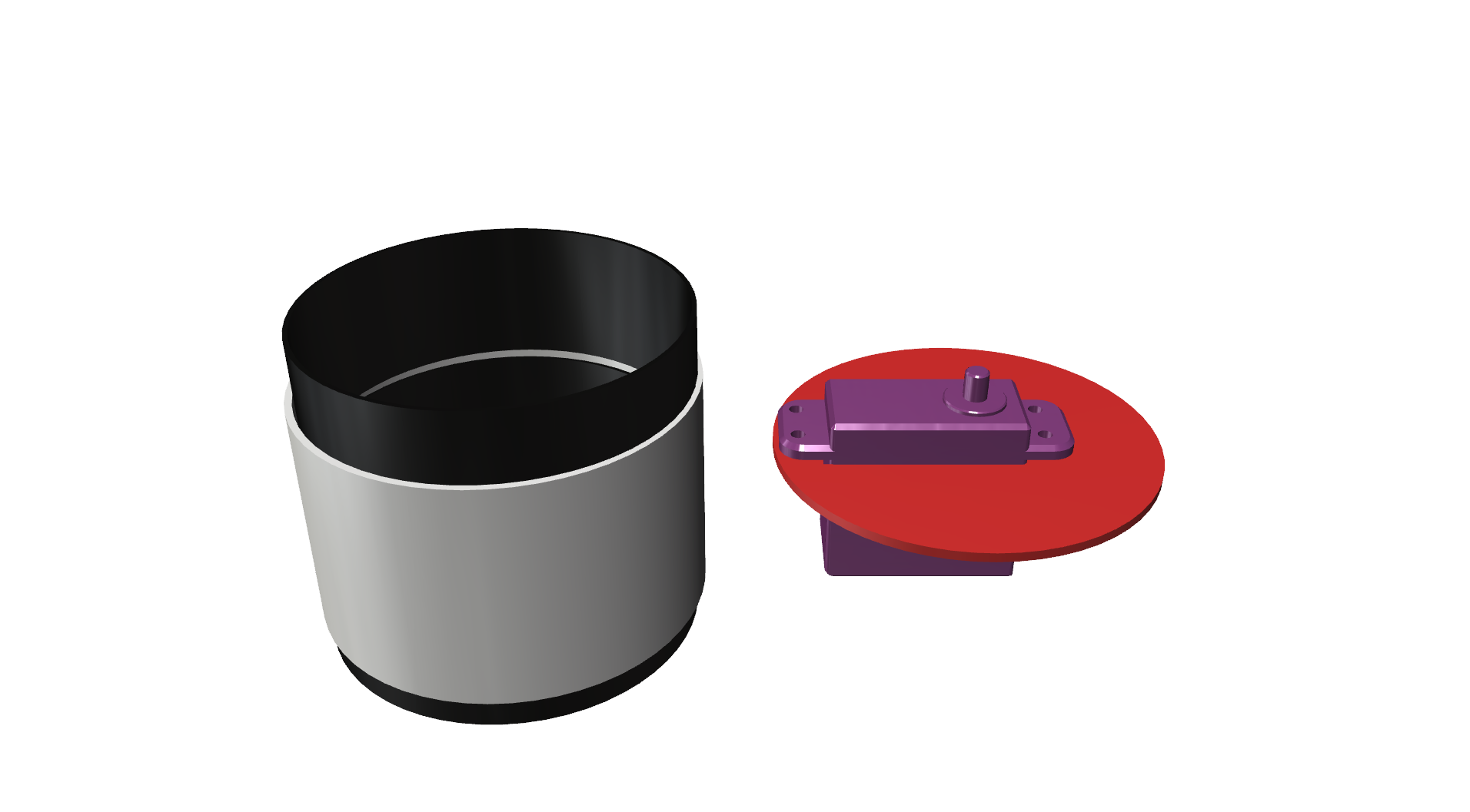
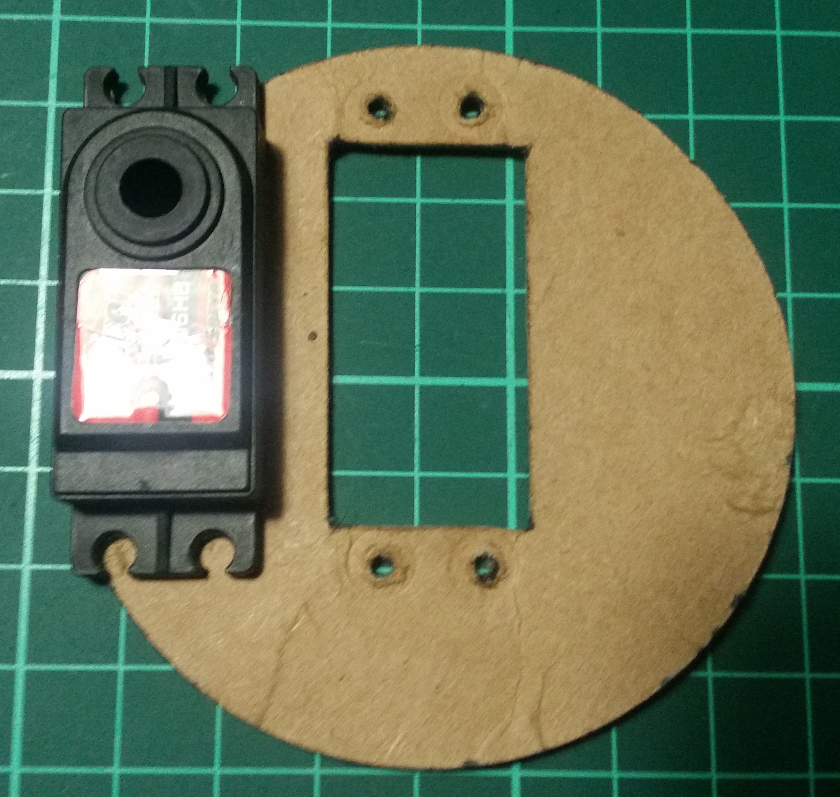
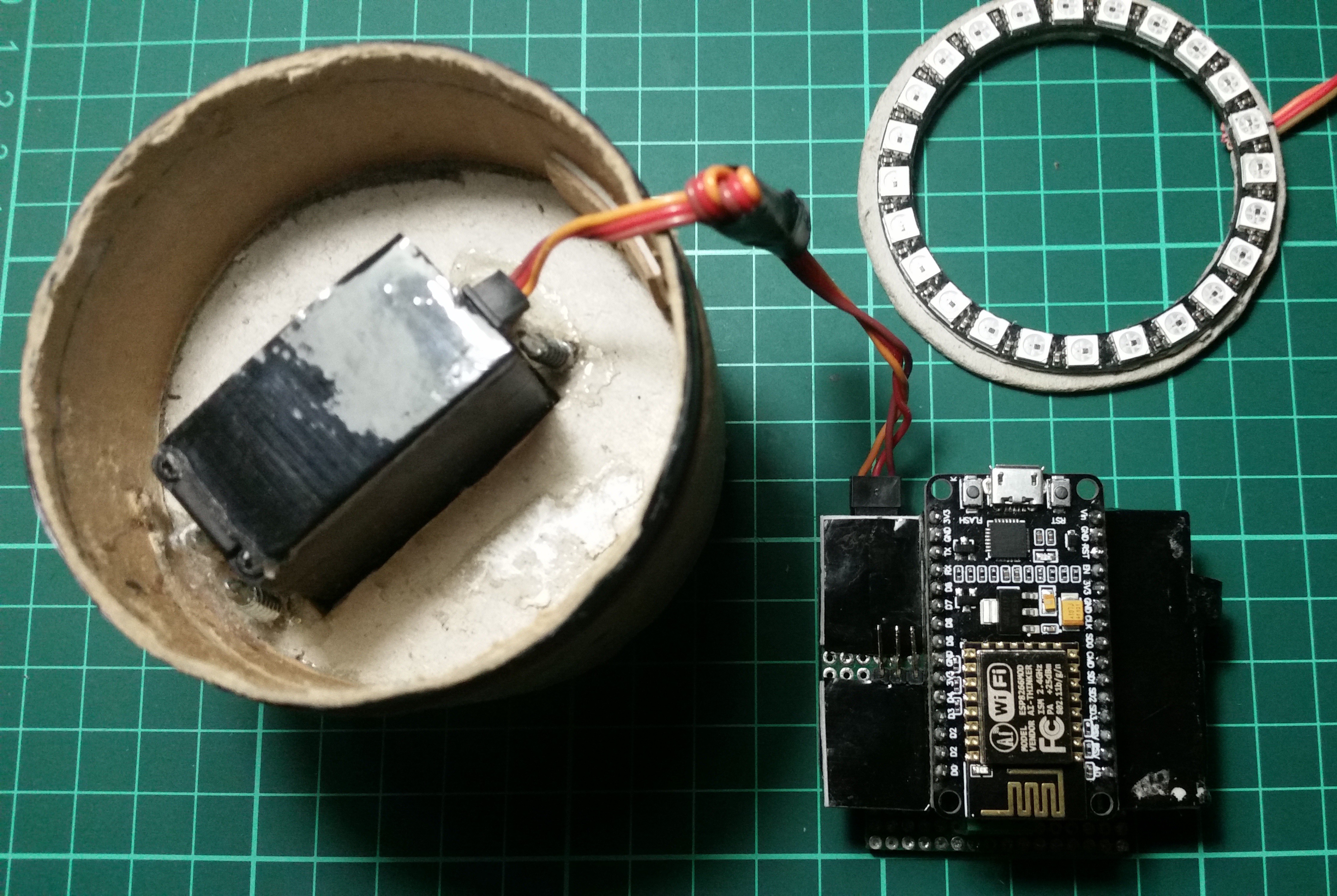
Attaching the servo
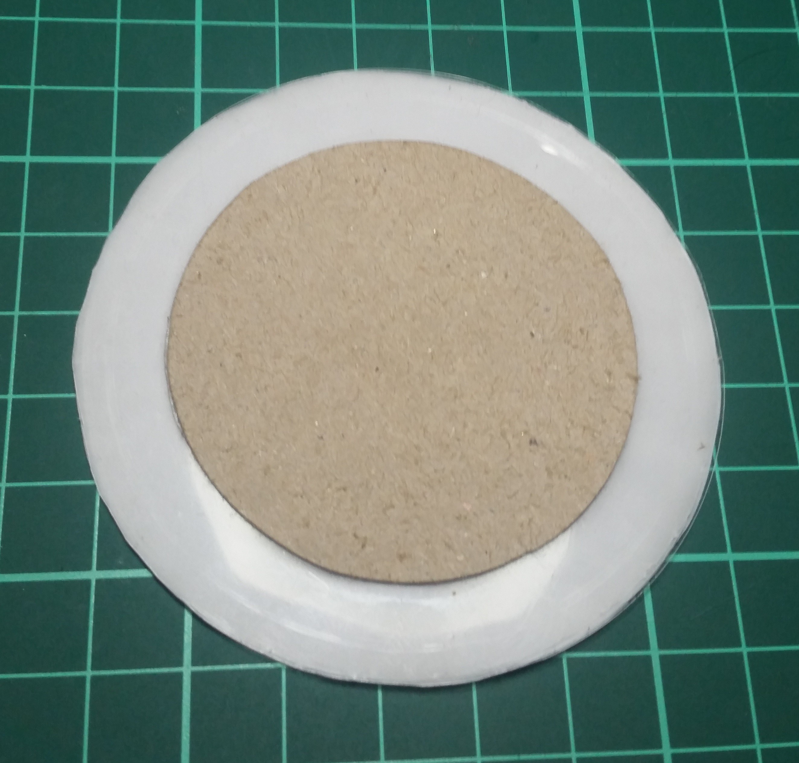
I used the servo shell as template while I'm cutting the servo holder. And I have used the inner cylinder to hold this servo holder disk.
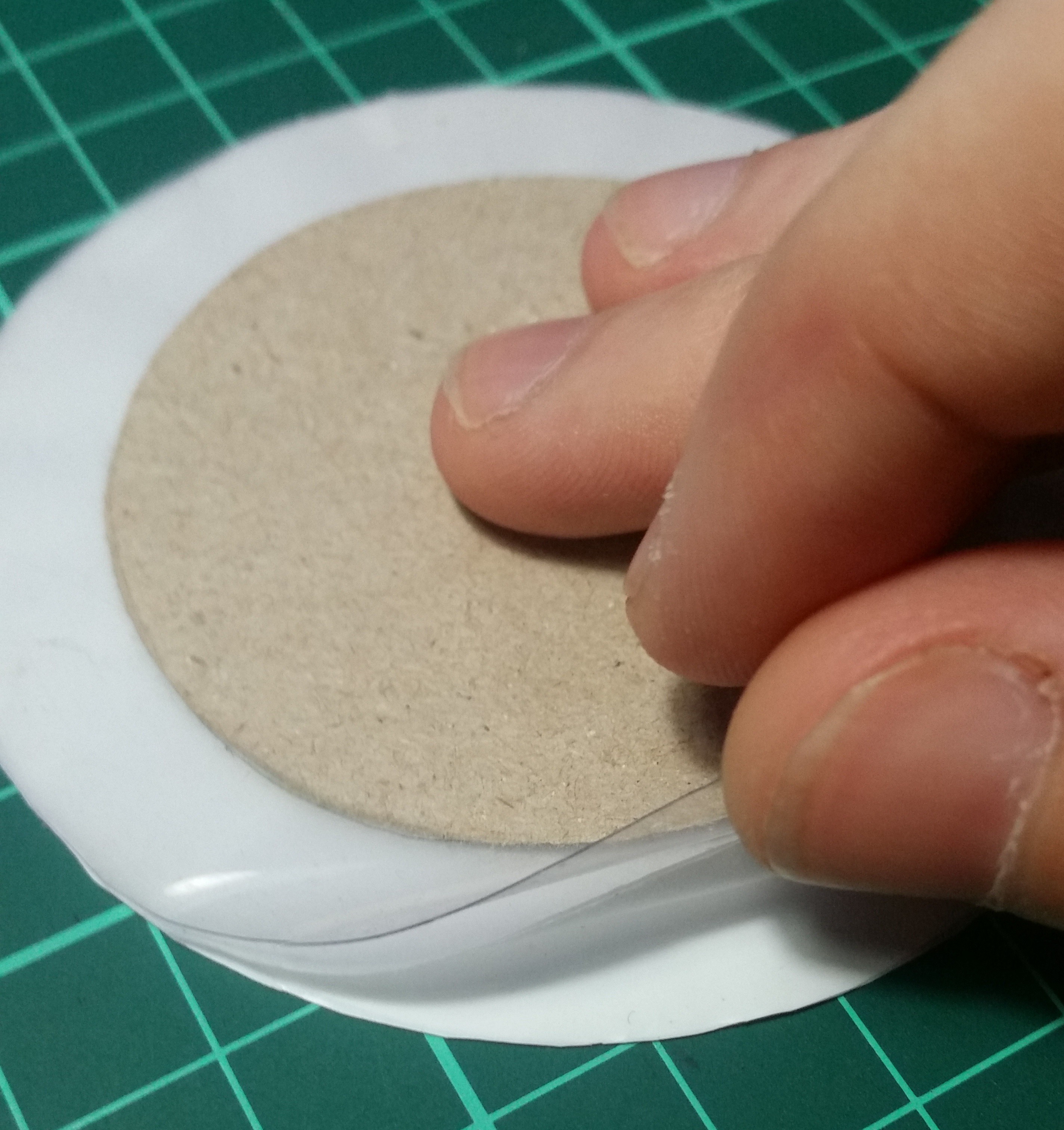
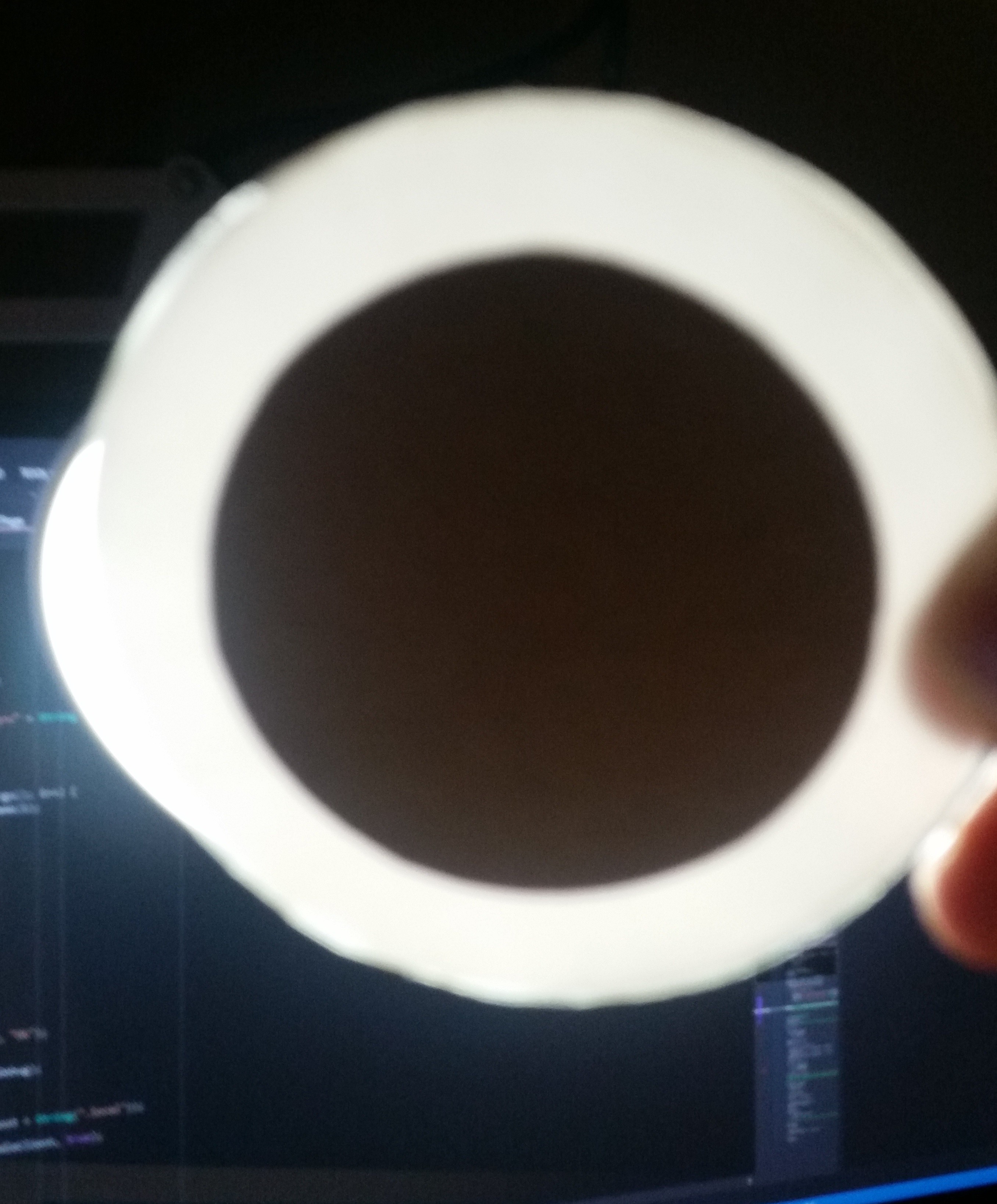
The Diffuser
I think the diffuser was the hardest part of the enclosure because you can't actually measure or decide how light acts on a transparent surface. Trial-and-error was the only way to build something like this. I do not want to see the individual LED's inside the box so I made a six layered transparent disk to spread enough light. Disk contains two full transparent layers both side. There are multiple plastic and paper layers at the bottom of clear layers.
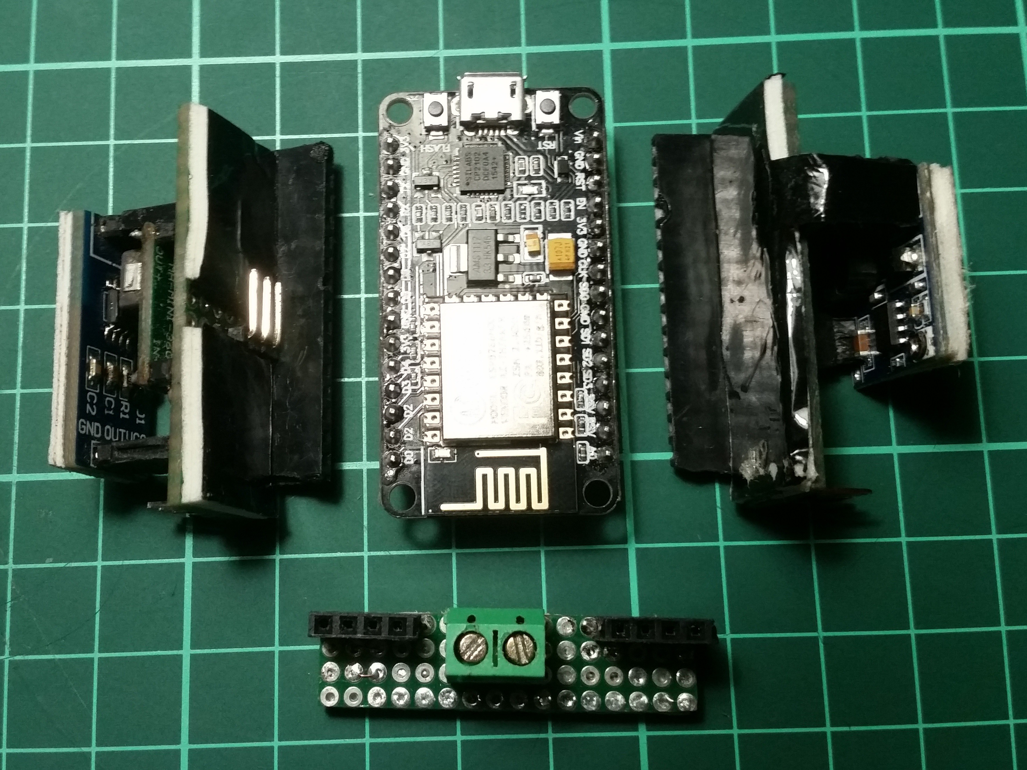
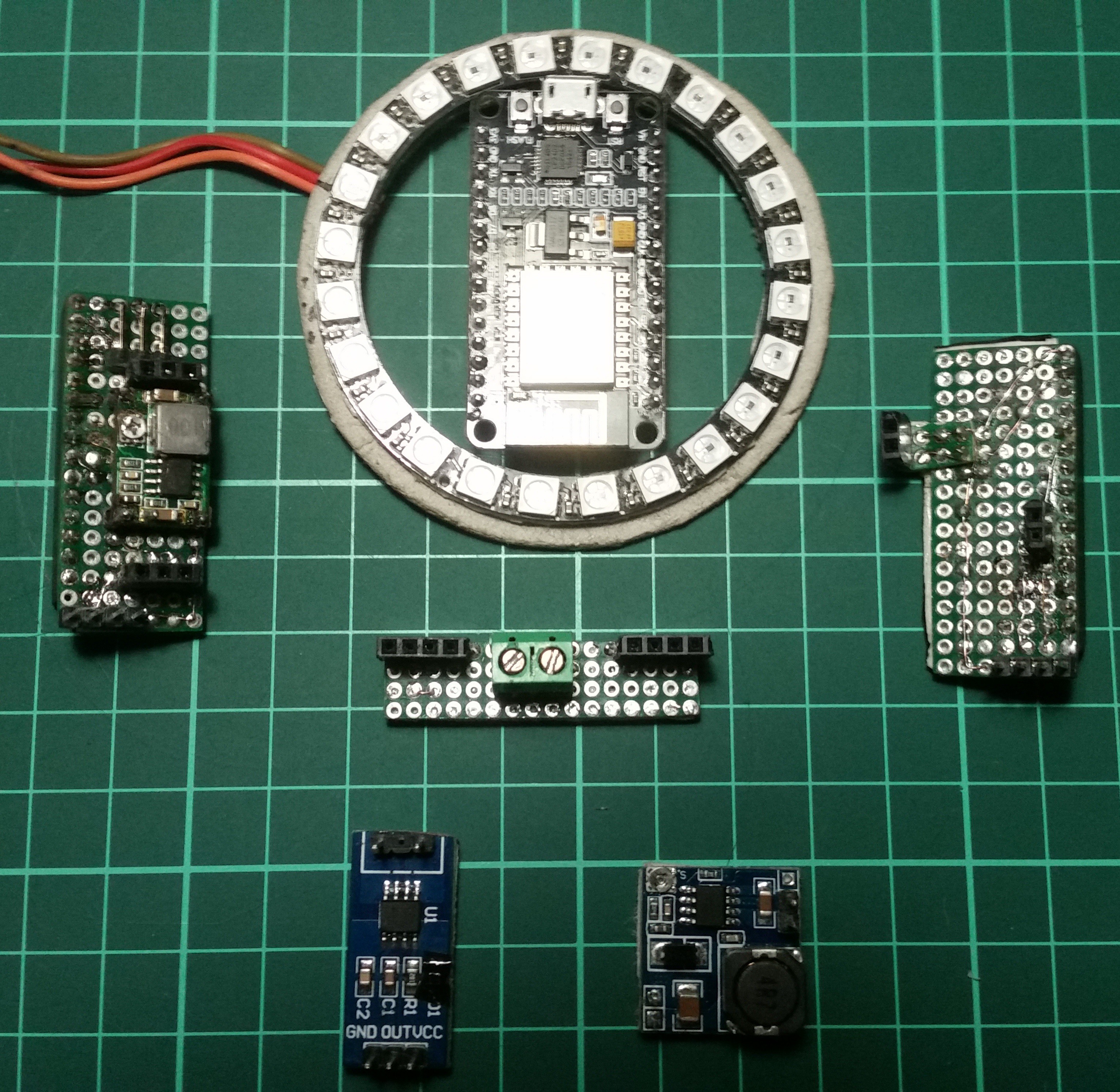
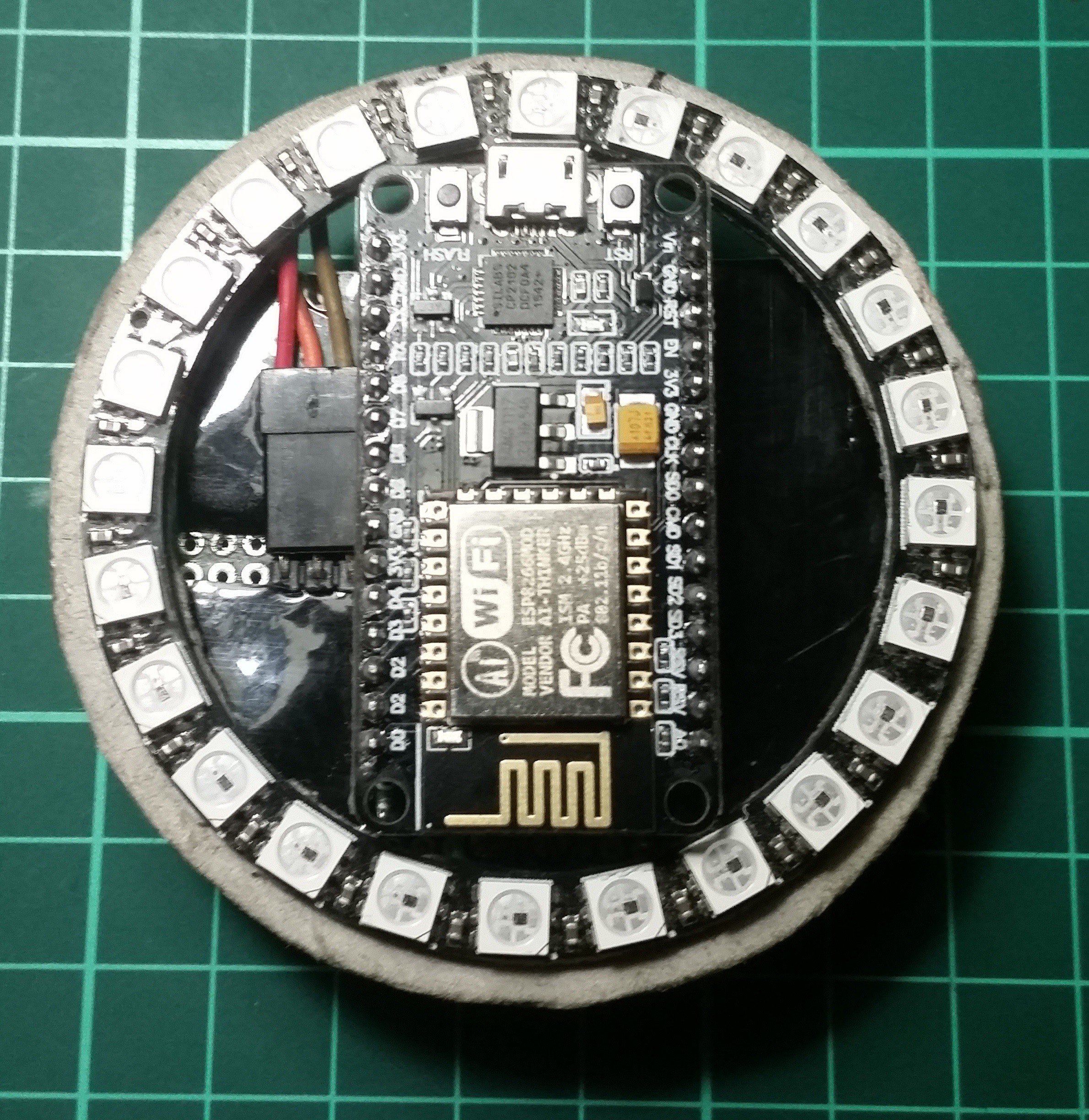
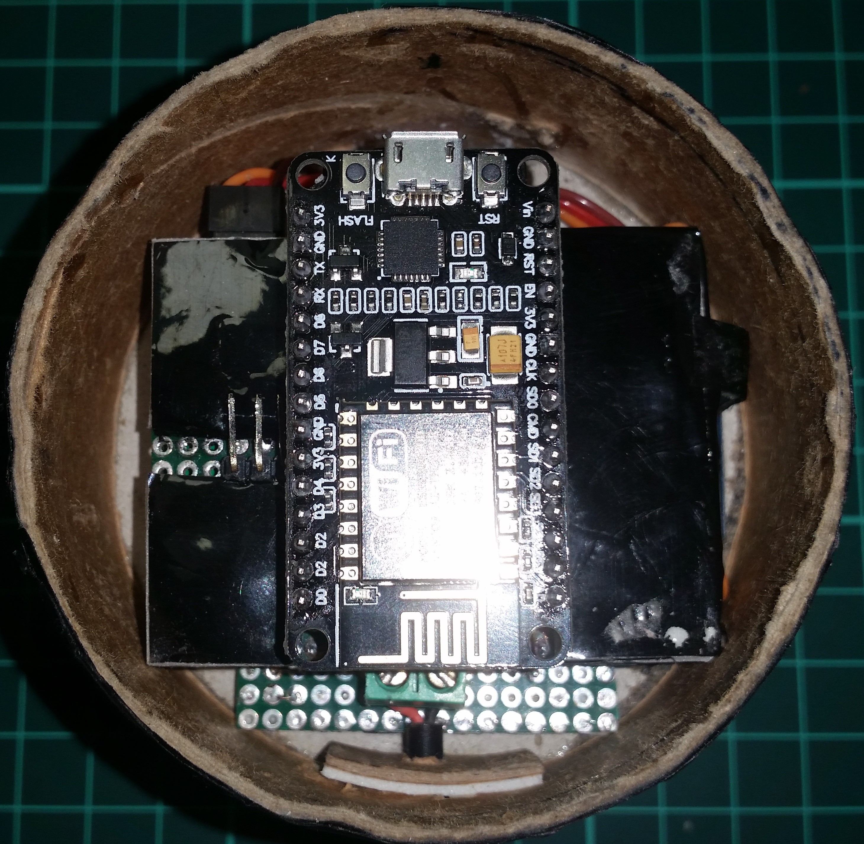
Electronics
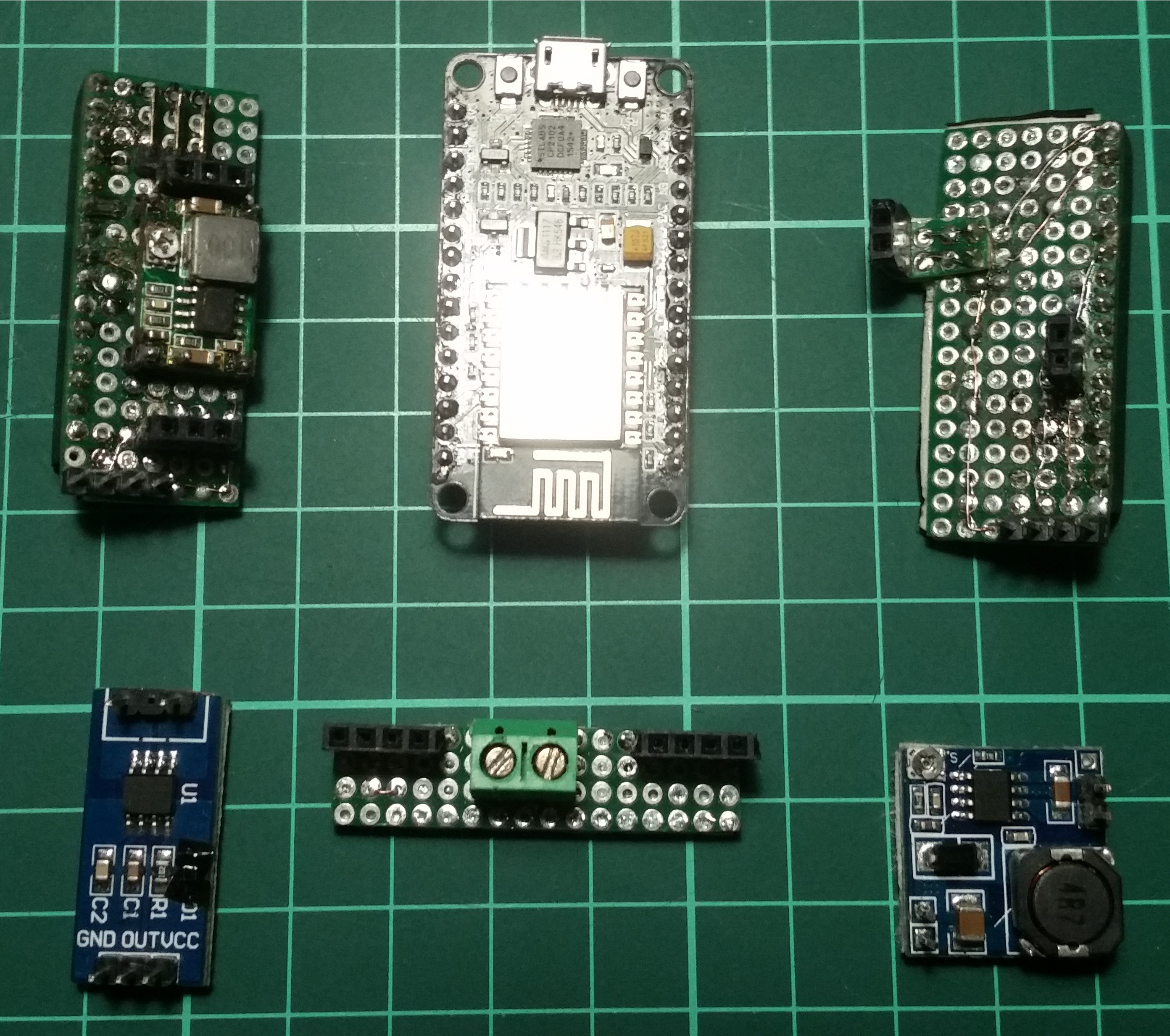
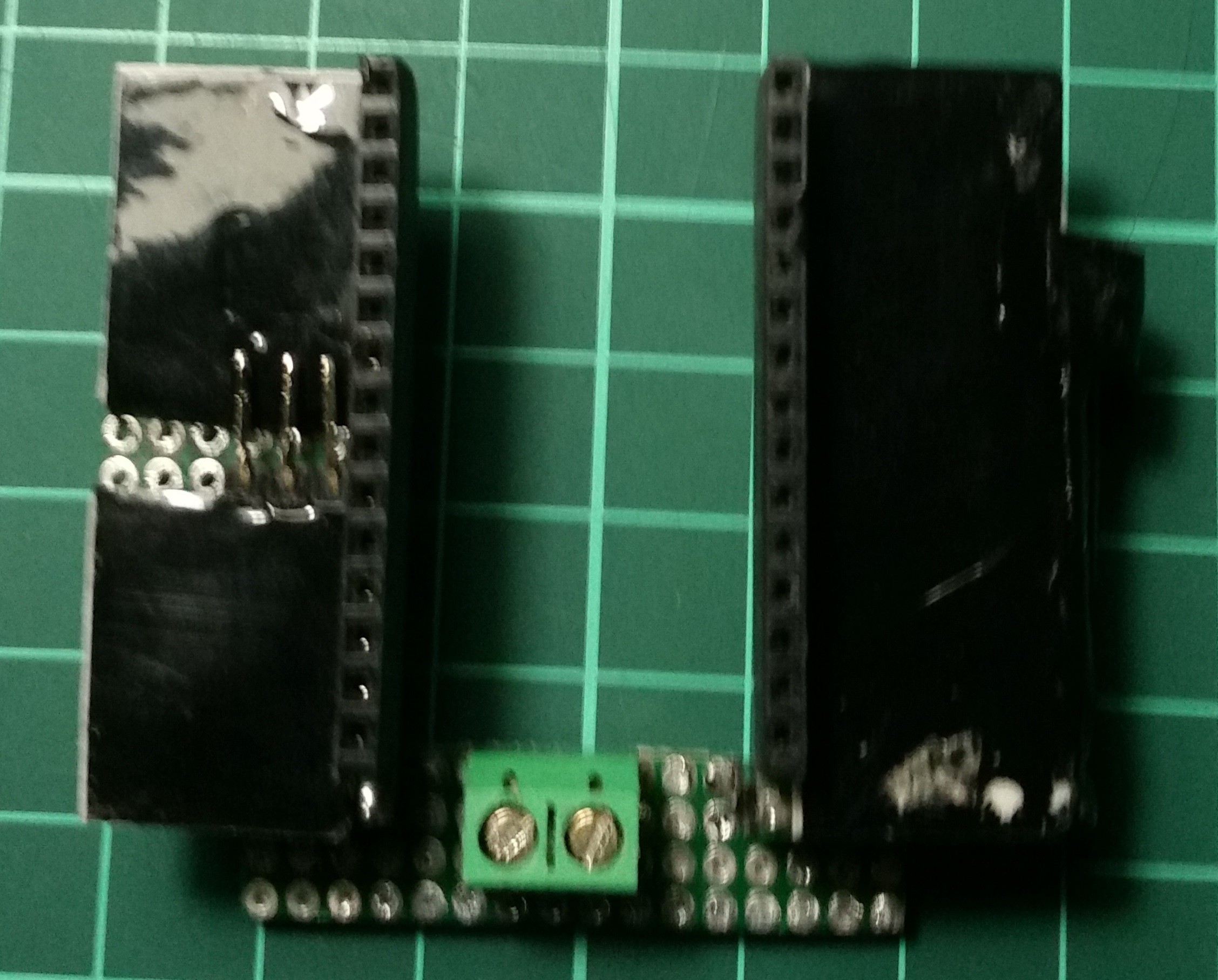
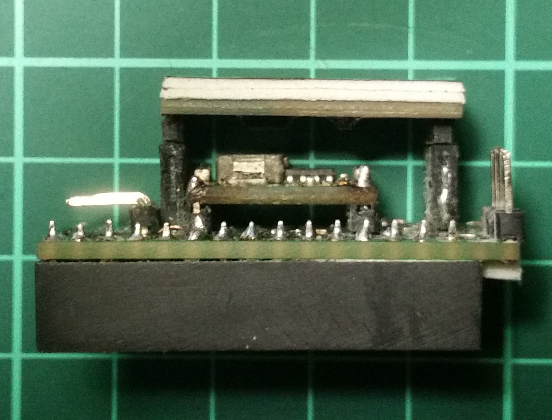
When I've mounted the servo, I've realized that there was not much space to put electronics in it. So I made some custom design by using standard prototype boards. I made the whole system modular so that I can replace or modify anything without building a new custom board. Basically whole board contains 7 different modules.
Device is powered with a 12v input and it has two step-down regulators on it. One of them is set to 6v for servo and the other one outputs 5v for NodeMcu. And also there is another regulator on the NodeMcu for 3.3v requirement of the ESP8266. I know that is too inefficient but I will fix it on the next version of the device.
- NodeMcu DevKit v1.0
- 24x RGB WS2812B led ring
- ACS712 current sensor
- Sensor board with servo regulator.
- Voltage regulator board for NodeMcu and crrent sensor
- Power distribution board
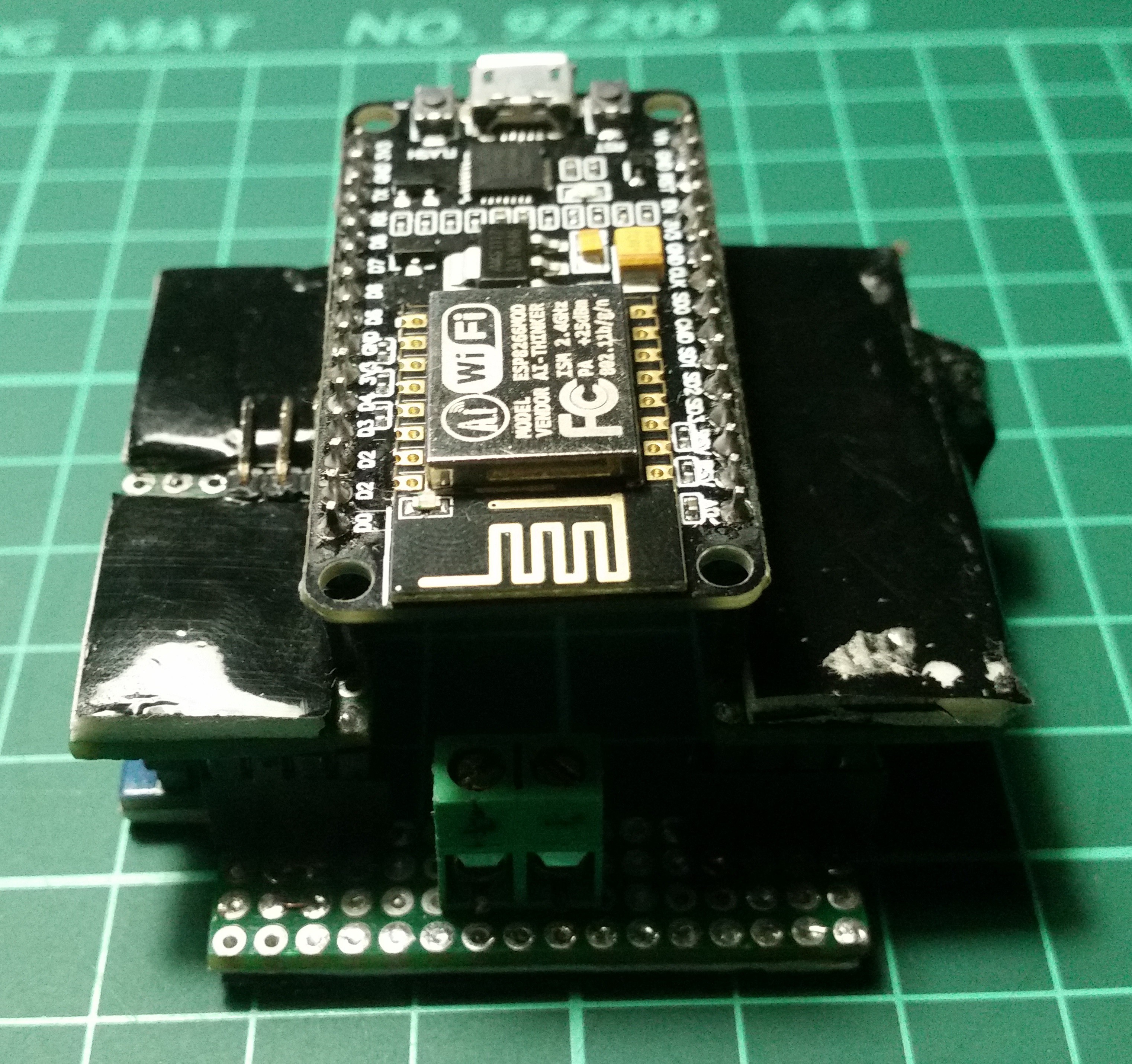
Final Assembly
Discussions
Become a Hackaday.io Member
Create an account to leave a comment. Already have an account? Log In.