Close
0%
0%

Smart status LED

Don't you hate it when your status LED is unreadable in bright light and blinding in the dark?

Similar projects worth following
I hate status LEDs! In daylight, I cannot see them, in the dark I cannot stand them; so I end up covering them with some tape. So I decided to design an alternative. A small device that lights up an LED proportional to the ambient light, and offers different modes: on, off, blinking and flashing. Maybe I'll create a drop-in replacement to LEDs too.

Turns out this project is extremely straight-forward. Not sure it even deserves a spot on hackaday. Well, at least it was mostly done in a day and the code looks like a hack.

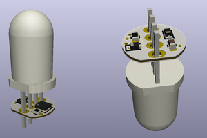
See the gallery for the finished prototype. It has the form of a tiny development board for the ATTinyX5 family with six pins for programming and one status LED.

When programmed with the code below and connected to power, the LED will be off by default with the device powered down (current drawn 0.1 uA). Pull one of the status pins down to activate the LED.

  • Pin PB0: Turn LED on
  • Pin PB1: Blink LED
  • Pin PB2: Flash LED

If several pins are pulled low, flashing has the highest priority followed by blinking.

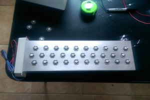
See the gallery for a comparison between dumb and smart LEDs. My tiny ATTiny "development" board is also pictured. It's maybe hard to see in the pictures, but in real live, the difference between dumb and smart is huge. It's a real relieve to the eyes. Maybe I'll start to like status LEDs after all. At least smart ones.

Power consumption by the microcontroller is still a bit high. Also, if anyone has further improvement ideas for the code or the design, I'd be happy to listen.

plain - 3.90 kB - 05/30/2016 at 13:05

Download

  • First steps

    Thierry05/29/2016 at 13:09 0 comments

    I built a first quick prototype today and it works - kind of, using an ATTiny25 and my favorite yellow LED. No blinking or flashing as for now.

    The prototype does just one thing. As soon as power is on, it measures the light level and adjusts the brightness of the LED accordingly. It's set up in an endless cycle:

    • Reverse-bias the LED
    • Wait a bit
    • Measure Discharge with the ADC
    • Compute brightness level
    • Turn on LED for the appropriate fraction of time (maximum duty cycle 50%)

    At 3V, the maximum duty cycle of 50% means that it is safe to forgo the resistor on the LED. The prototype does works in the sense that it indeed adjusts brightness correctly. My multimeter agrees:

    • 670 uA without LED
    • 700 uA with LED in complete darkness (i.e., LED drawing only 30uA )
    • 5.7 mA in bright light (i.e., LED drawing 5mA)

    There are still some limitations:

    • The LED discharges a bit even in complete darkness. I will have to understand the source and nature of this discharge to make the design more robust
    • Blinking and flashing modes are missing.
    • The current used by the microcontroller is a bit high for my taste.

    Still, I am satisfied with the first results.

View project log

Enjoy this project?

Share

Discussions

Similar Projects

Does this project spark your interest?

Become a member to follow this project and never miss any updates