Optic Box:
For making the device screen people with different refractive error the optic box had to be moved inside the casing. To achieve this, a sliding system was created by making positive rails on the optic box and negative rails inside the casing.
Optic Box
The box has stress at the edges as its weight is concentrated at the rails. Hence the strength of the edges of box had to be increased. Holes at the edges were provided for mounting screw fasteners to increase the strength of the optic box.
Sliding System with Rails
Rack and Pinion Mechanism:
To impart motion to optic box, rack and pinion mechanism has
been used. The rack has been placed on the optic box and the pinions are
assembled inside the eye piece with a rod which transmits motion to different
planes and eventually to the racks. The pinions are assembled inside the eyepiece with the help of a bracket. The bracket holds the pinion in its place while giving it freedom to rotate in the plane.
Rack and Pinion Assembly
LCD:
The Waveshare 5 inch LCD has mounts to assemble the LCD onto a surface using screw fasteners.
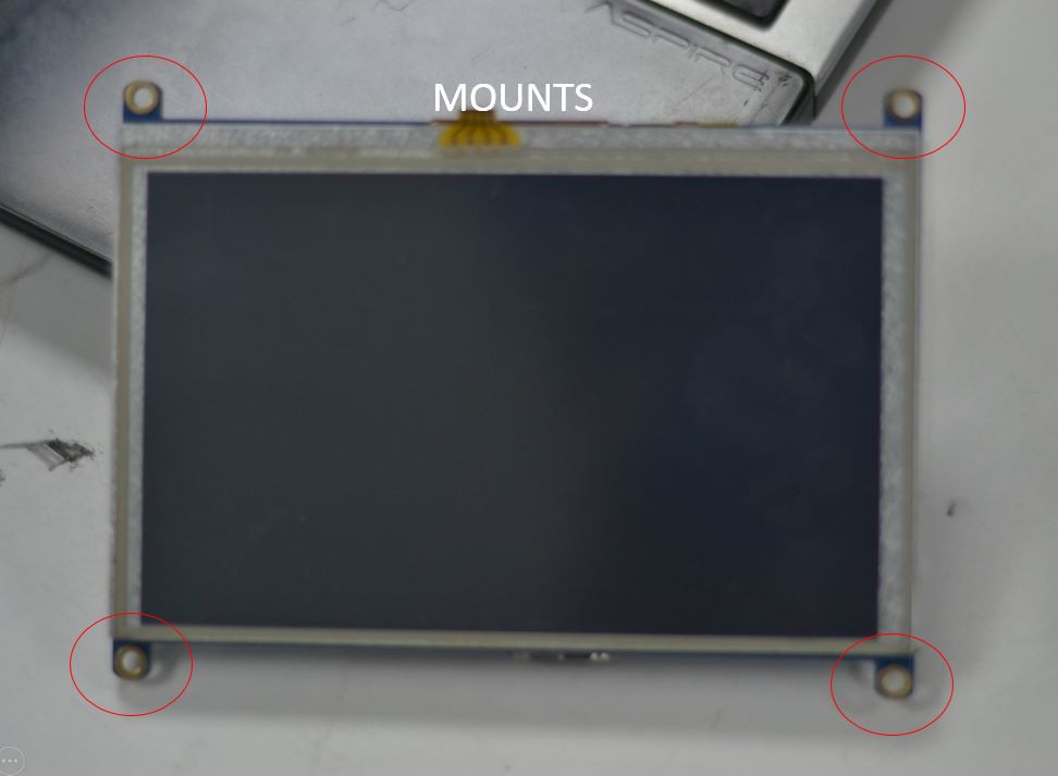
LCD with mounts
But, to accommodate the LCD inside the front casing we have to cut the mounts that come with the LCD.
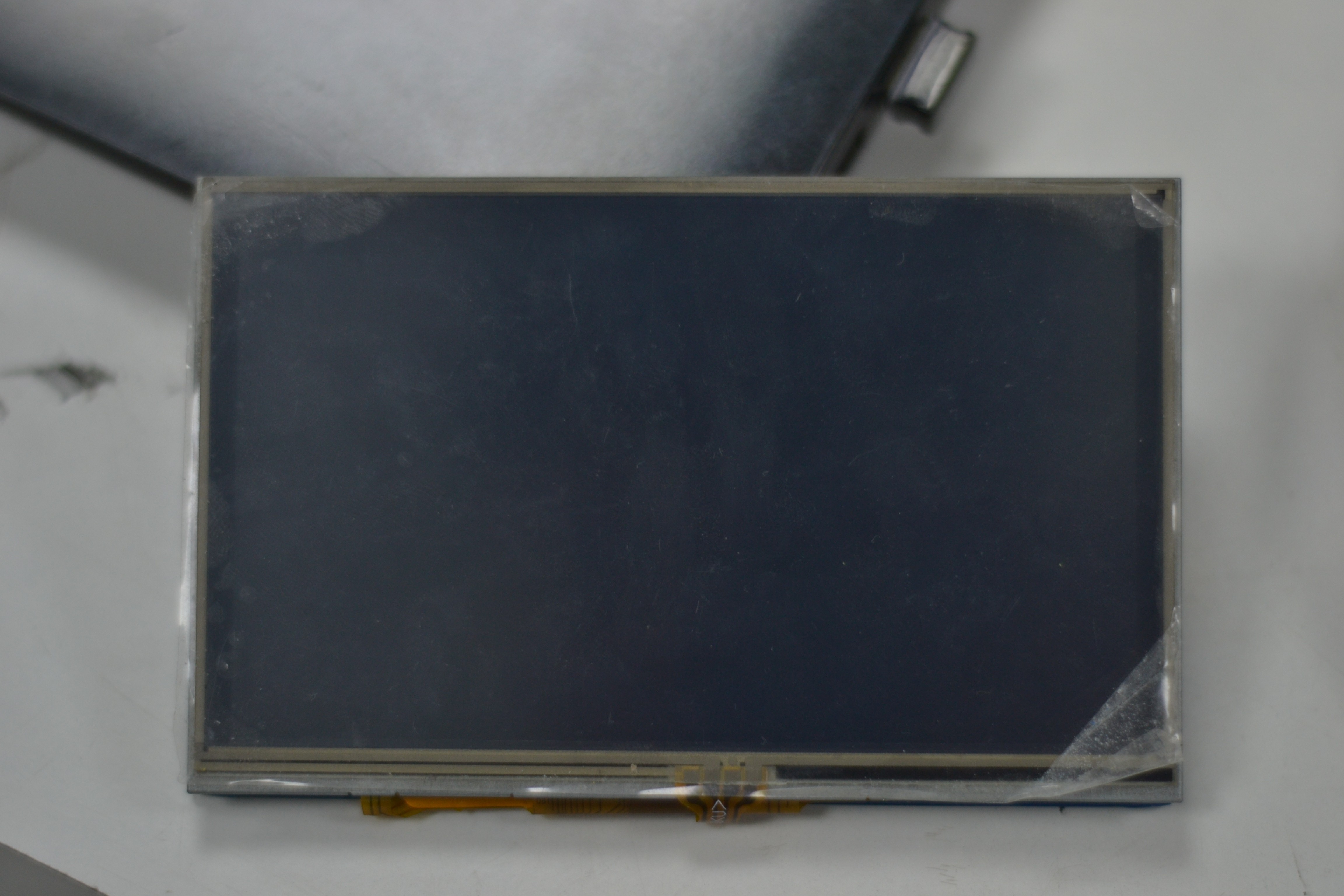
LCD without the mounts
To assemble the LCD with the Front casing we made a support for the LCD which would act like a mount for the LCD.
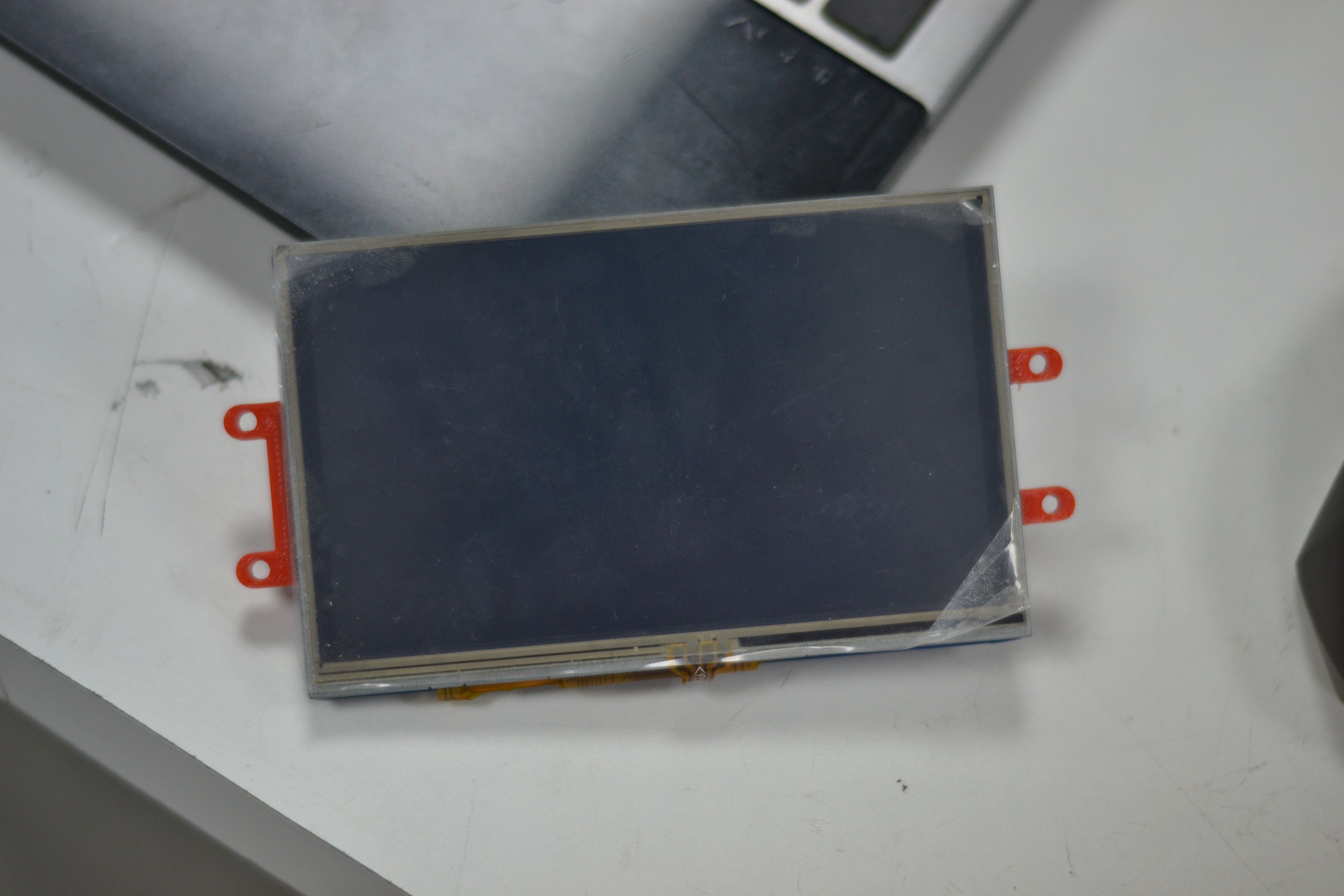
LCD with printed support
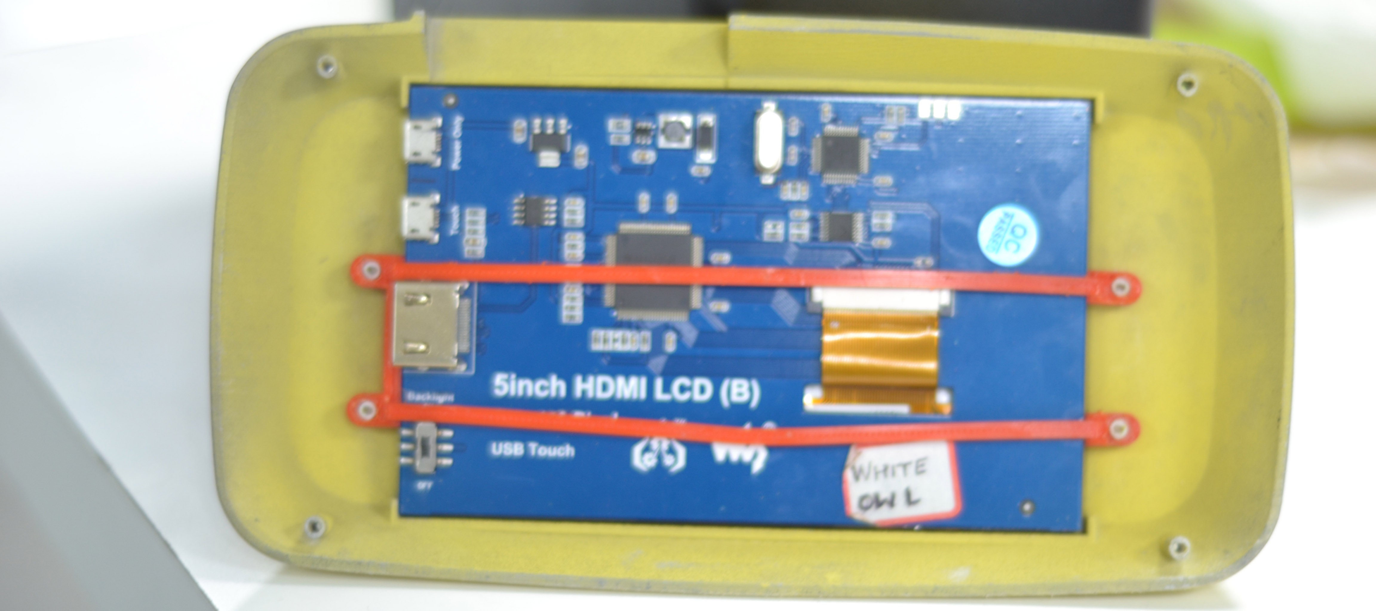
LCD Assembled inside the middle casing

PCB of Batteries:
The PCB of the Batteries has to be placed inside the Middle casing. To assemble it inside the middle casing a mount has been created on which the PCB is fastened with the help of nut and bolt fasteners.

Batteries with the PCB
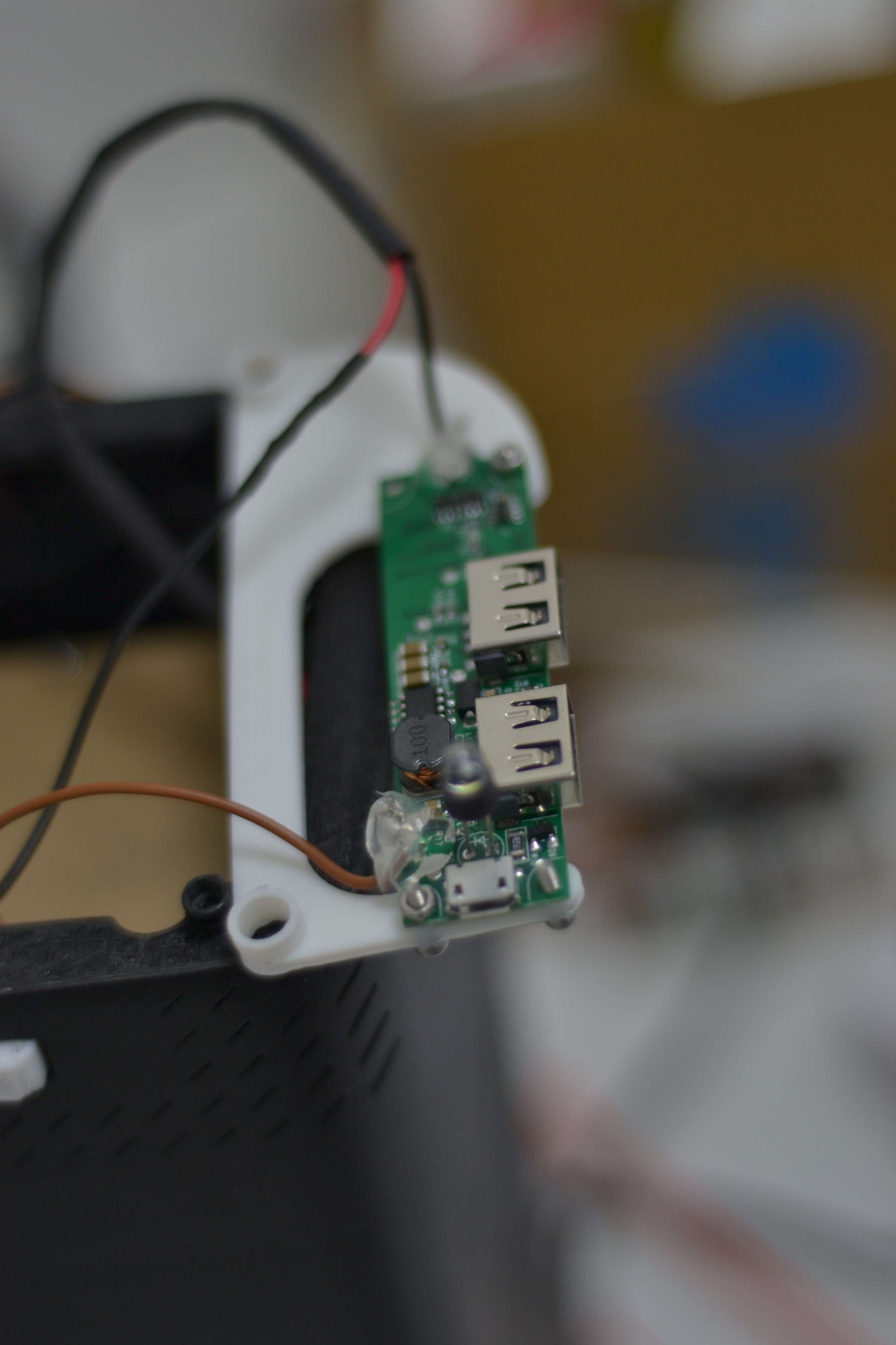
PCB with the mount
Click Switch:
The Click switch has been mounted inside the middle casing using a mount. It is first mounted into the mount and is then assembled inside the middle casing using screws.

Mount for Click Switch
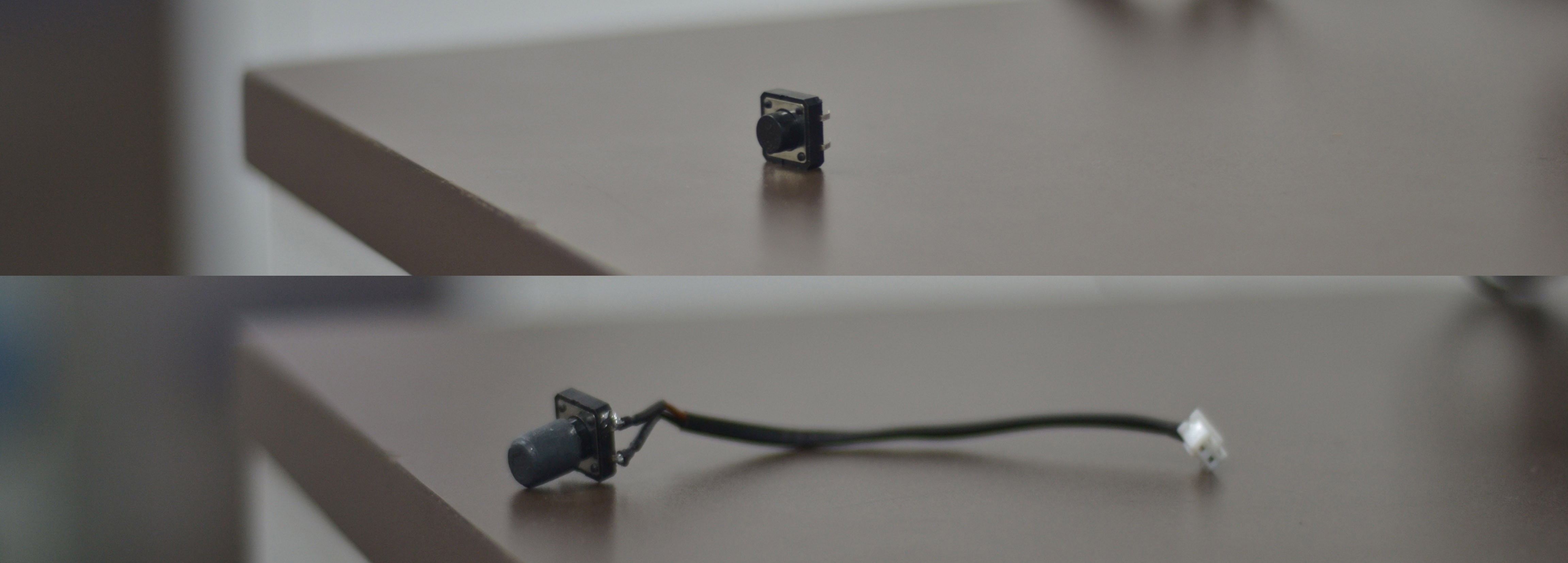 Click Switch
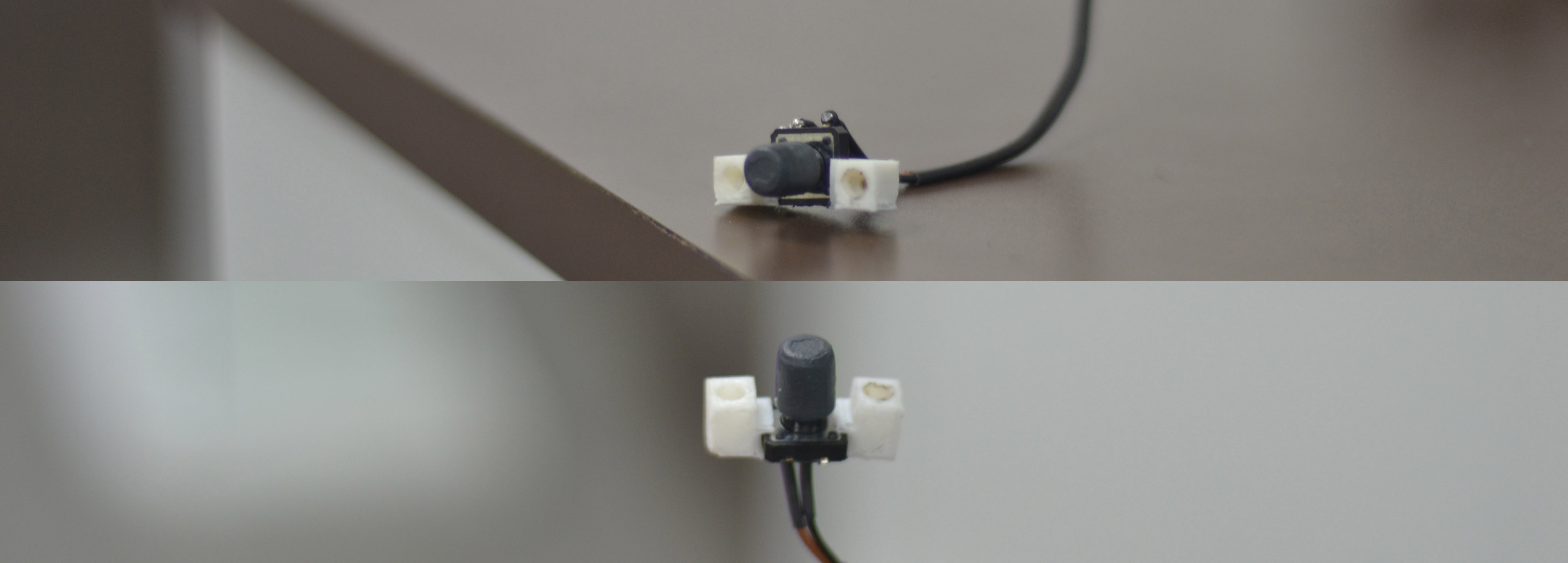
Click Switch with mount
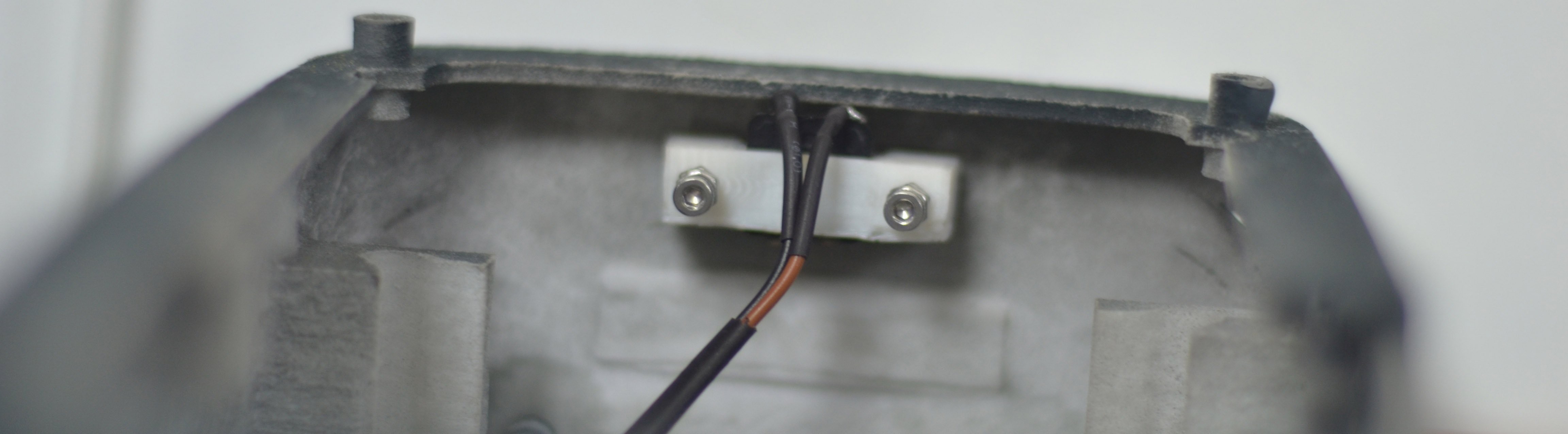 Click Switch Assembled inside the middle casing
Knob:
The knob made earlier was slippery, thus the total motion imparted was not transmitted due to slipping. The knob is given texture to increase grip and friction and help in transmitting motion to the rod.
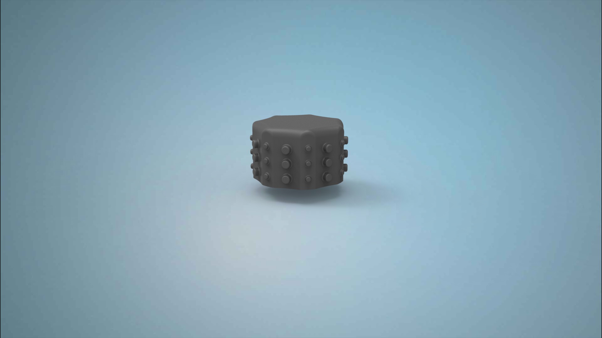
Textured Knob
Toggle Switch:
To regualte power to raspberry pi and LED's, a switch has been incorporated in the pcb. But there wasn't any switch to on/off the LCD screen. Thus a double switch was made which would facilitate as a switch to both the screen and raspberry pi,LED.Here are some of the images showing the making of a double switch.
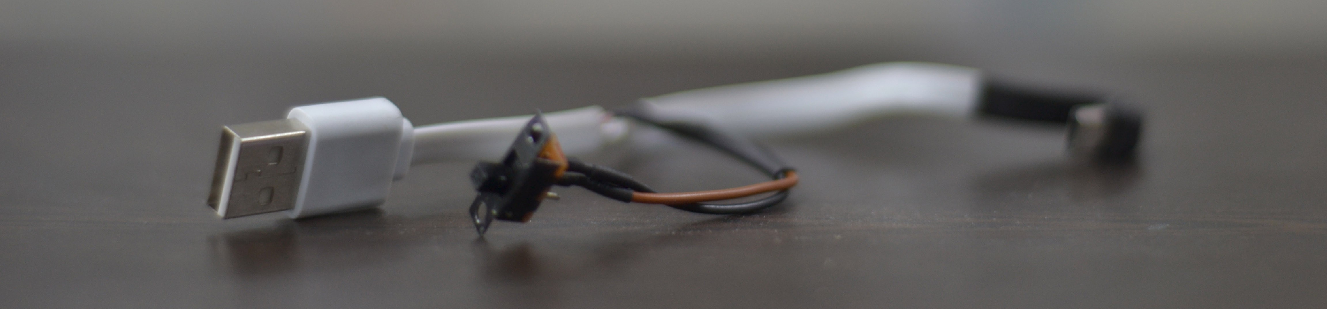
The Cable with a switch

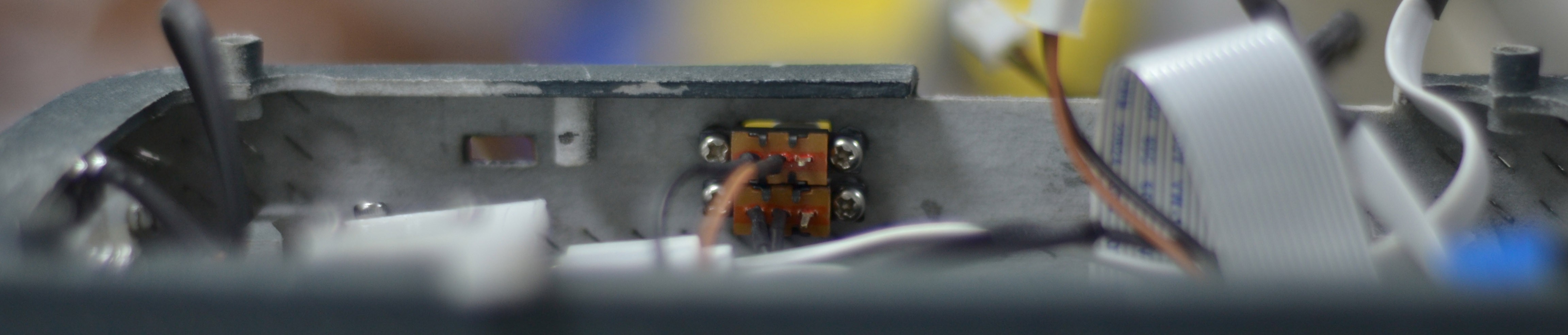
Double Switch
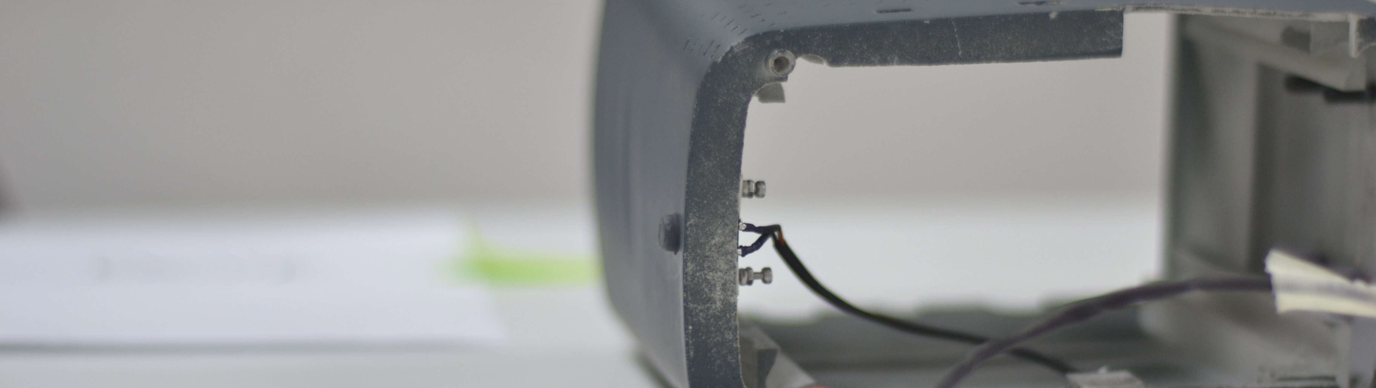
Double Switch inside the Middle casing
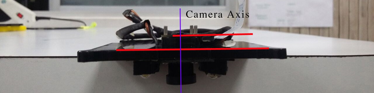
Camera Spacer:
To mount the camera to the Optic box a 4mm mount is used to create space between the optic box and the camera. This is needed to ensure that the camera is perfectly centered and parallel to the plane of sight.

Spacer

Camera without spacer
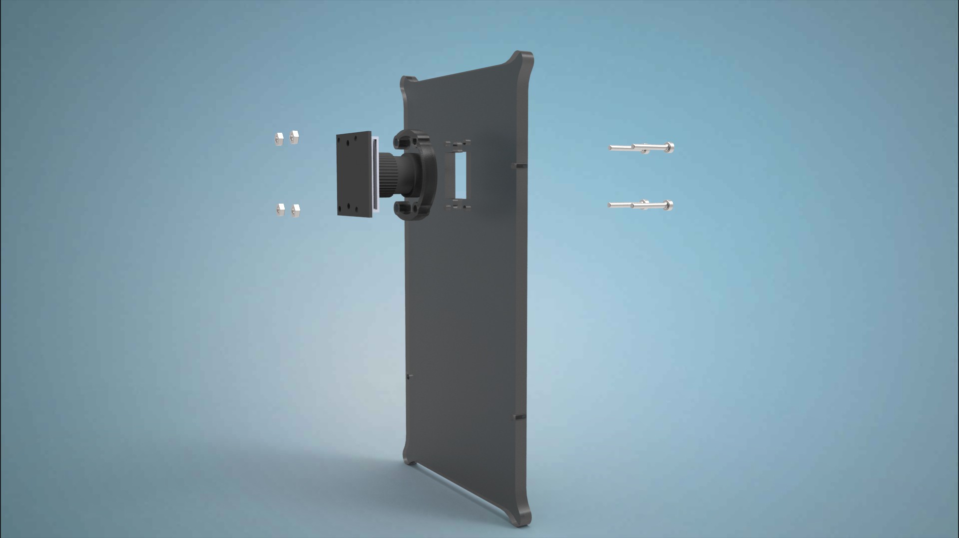
Assembly of Spacer with camera and Optic box
Discussions
Become a Hackaday.io Member
Create an account to leave a comment. Already have an account? Log In.