 BTom
BTomUPDATE: current version: https://hackaday.io/project/26073-bstya-v15
----------------
For the most detailed description please check out the project logs.
In the current state this robot can be used to demonstrate the possibility of this project, and 3D telepresence.
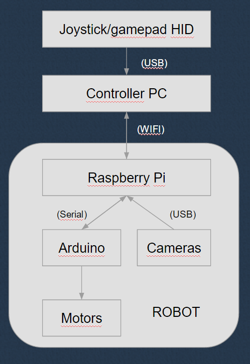
It is streaming video on wifi, and listen multiple sockets for head tracking control, and movement control.
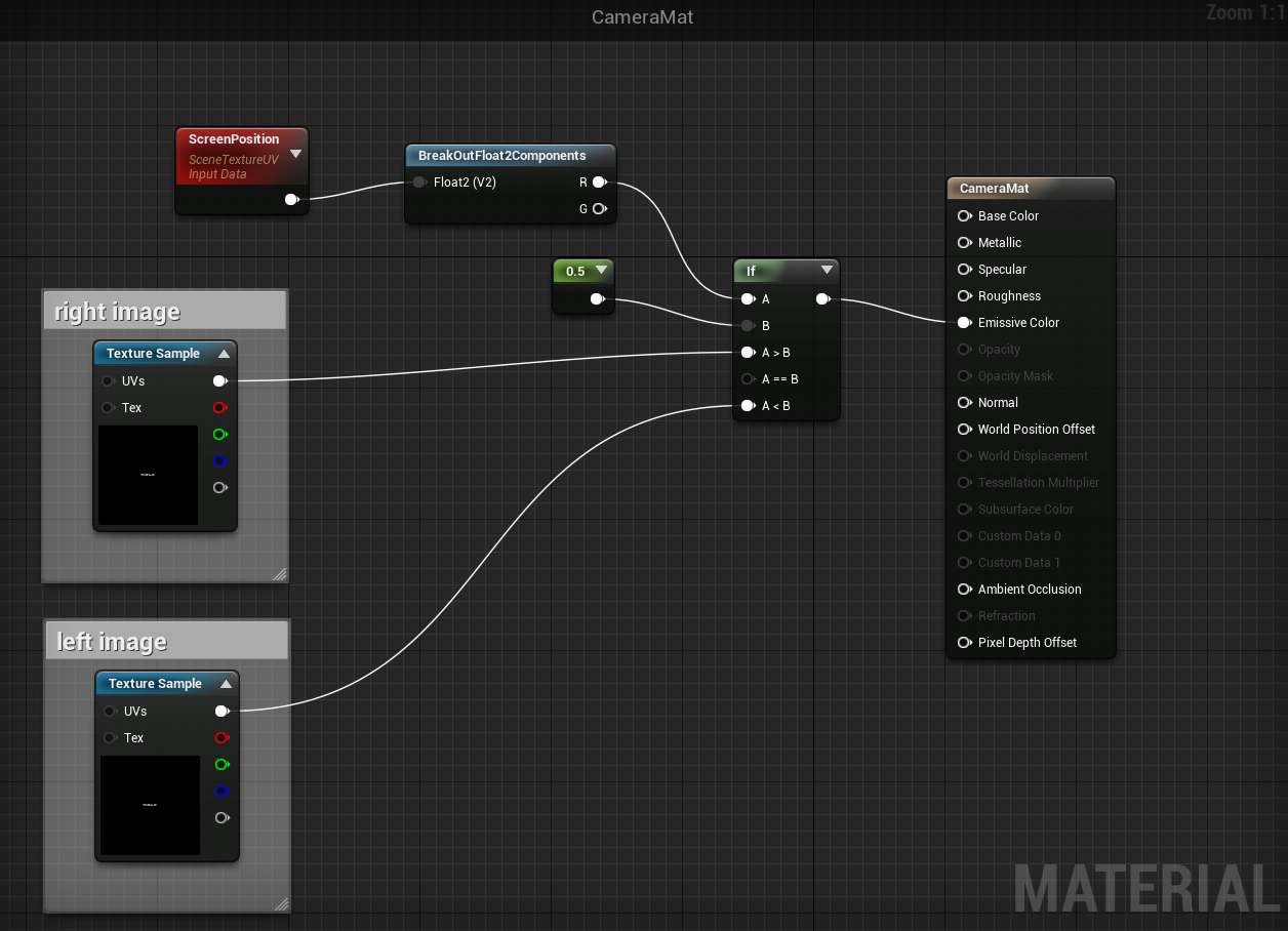
You can connect to the robot with HTML5 compatible browser and watch the video stream. Because of the HTML5 we can send the mobil device orientation back to the robot, so it can adjust the camera position in real time. You can control the robot movement with joystick connected to PC, or tablet.
Currently you have to use a powerful mobil device for high resolution video. Probably we will optimize the webpage with the video stream to the new google cardboard, or similar mobil VR devices for better experience, but our goal is to make this robot usable, with the most advanced VR equipment.
(we are using the version one google cardboard made from a pizza box for developing : )
We got a possibility to try out the robot with Oculus Rift DK2, so currently we are working on the Rift compatibility. With the Rift we think we can upgrade the user experience to the next level. And we will face new level of problems to solve. (like motion sickness while driving around the robot)
If you don't know something what we did, why we did that way, feel free to ask, and I will try to answer it.
We are glad if you make suggestions, or tell your ideas to improve our robot.
UPDATE: 2016-09-13
We had an opportunity to present our robot with the Oculus Rift DK2 at "DRONE PRIX HUNGARY ÉS A DRÓNVERSENY & ROBOTIKA SHOW" We go a lot of positive feedback.
You can view the images here: http://hungarianrobot.hu/wordpress/multbeli-esemenyek/dronverseny-es-robotika-show-2016-szeptember-10/


 igorfonseca83
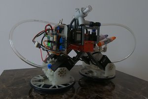
 Mykolas Juraitis
 Will Donaldson
Thank you for the comments, this is the current version of the robot: https://hackaday.io/project/26073-bstya-v15