 Kyle Gabriel
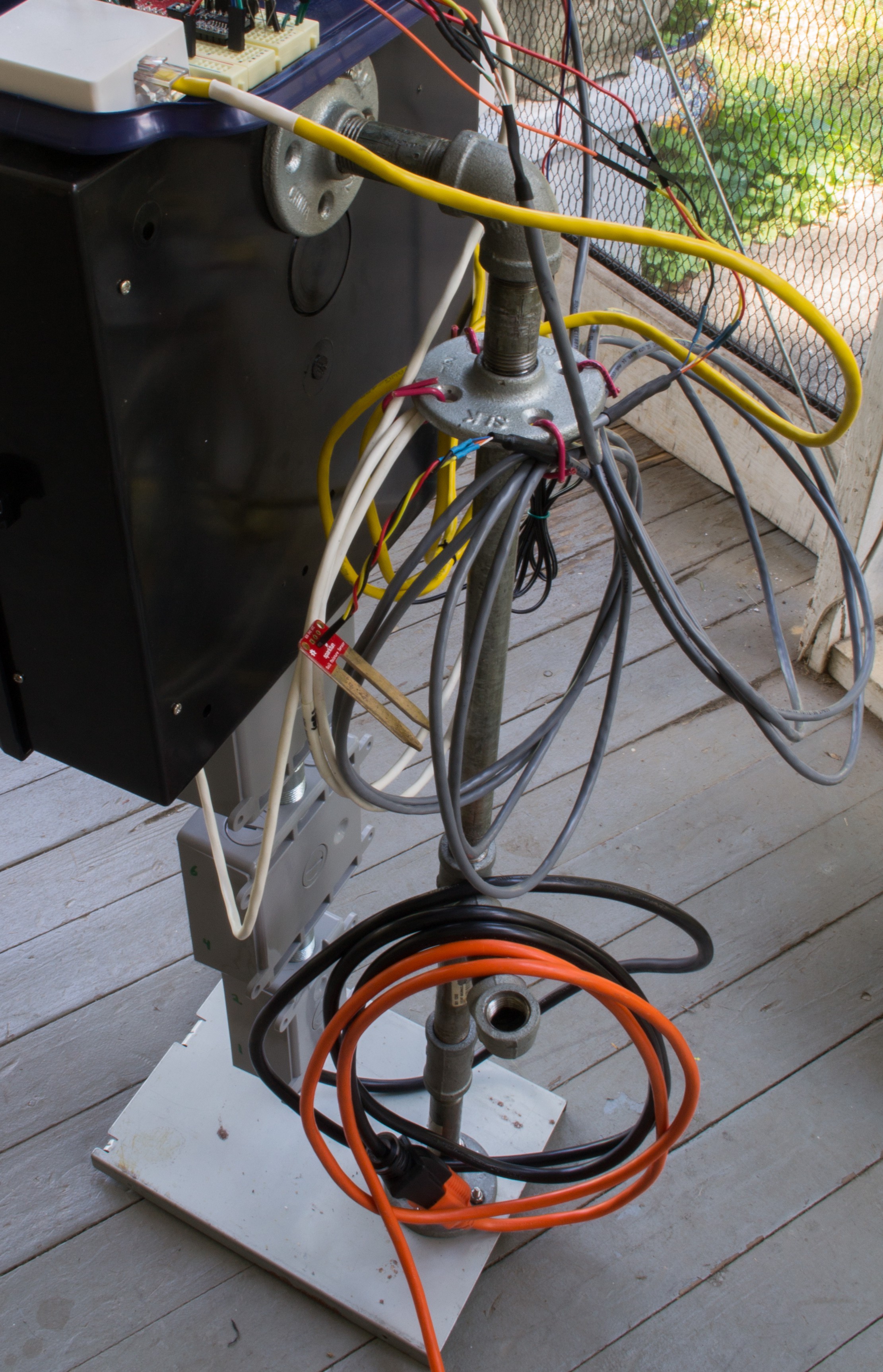
It was time for all the components to finally come together and to fully power the system. Power was fed through the bottom and passed through all outlet boxes.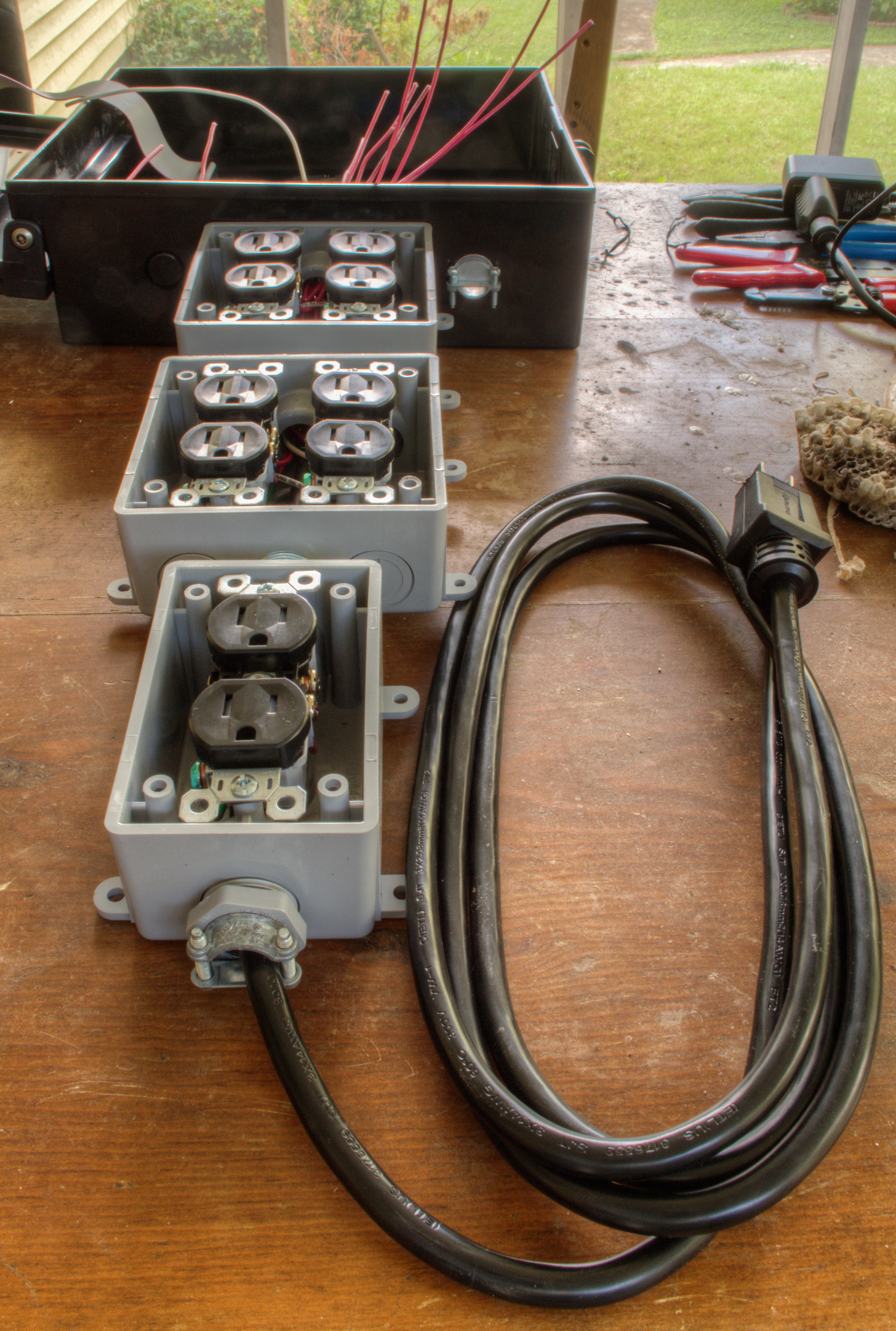
It's pretty tight at the very top, where all the wires must pass.
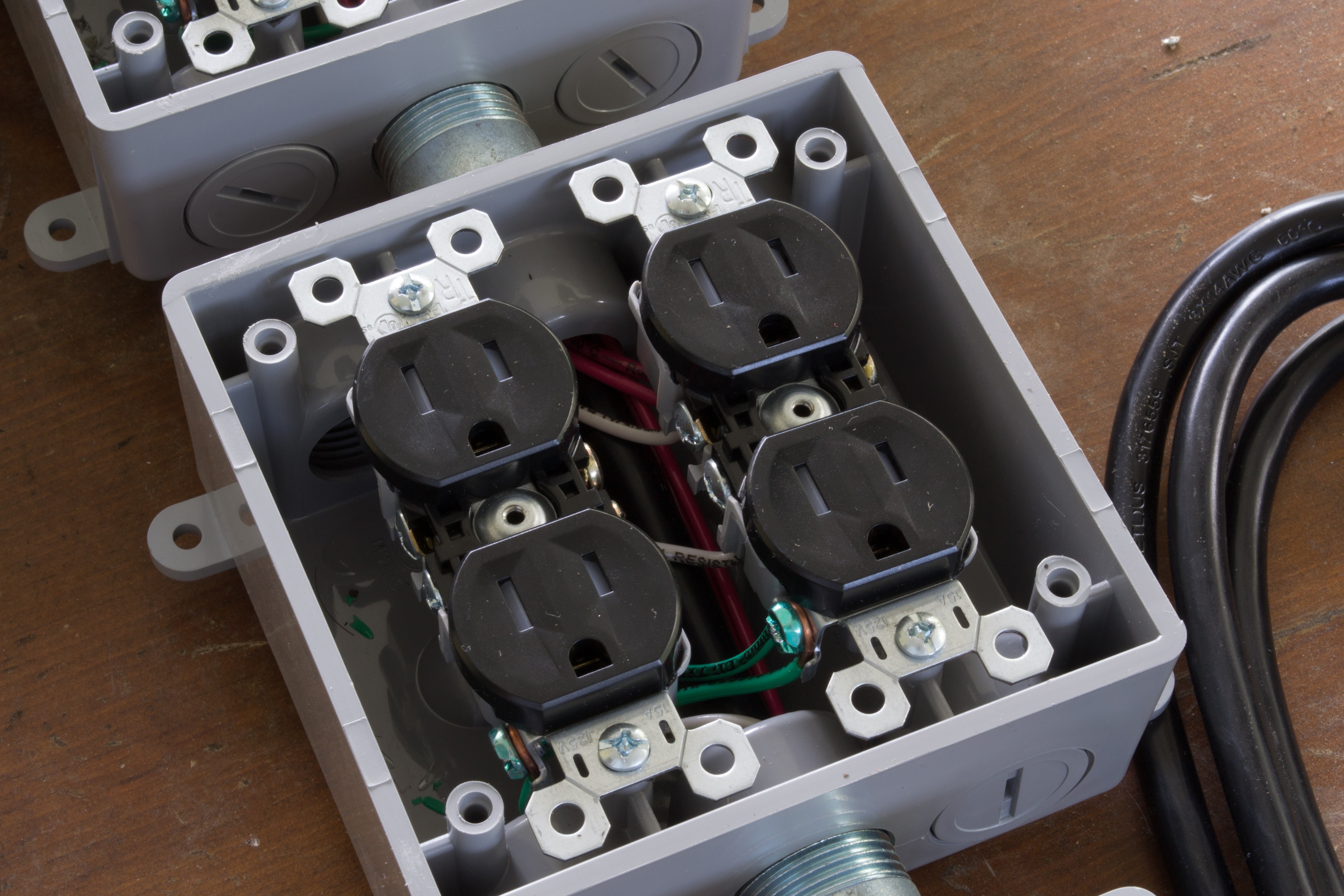
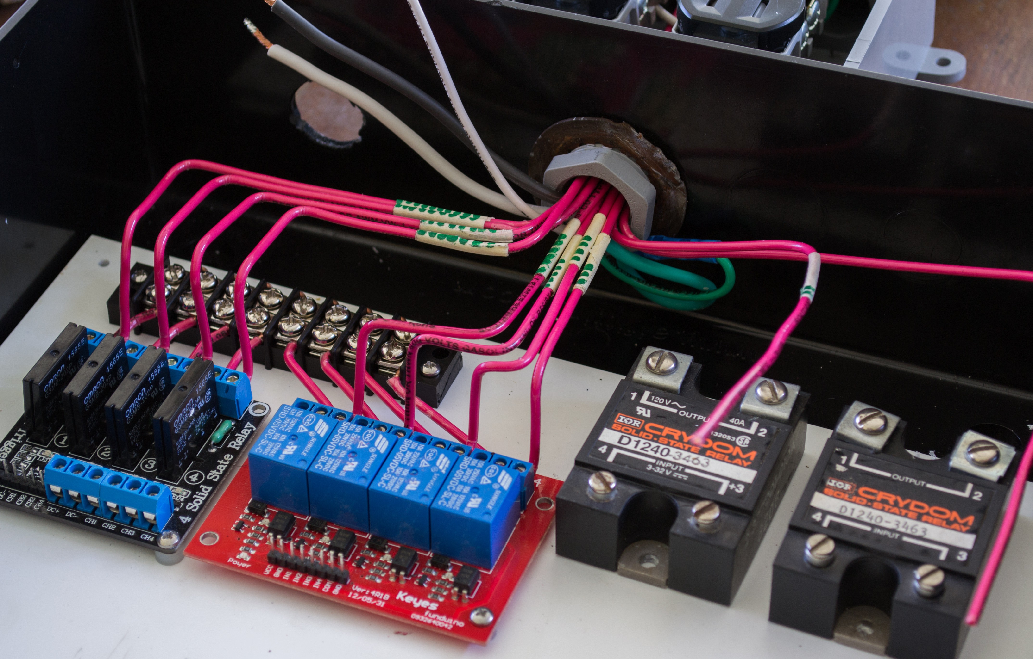
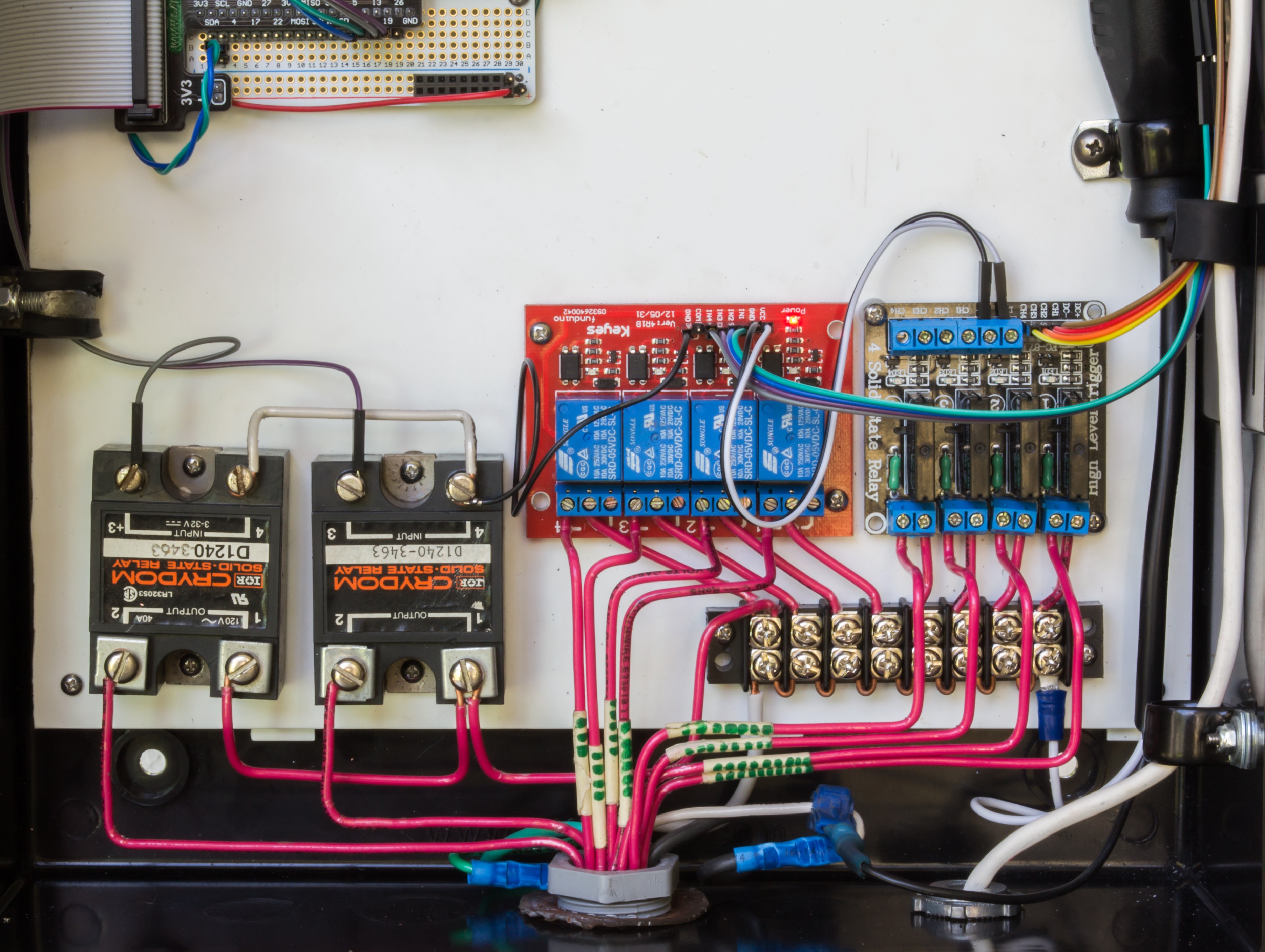
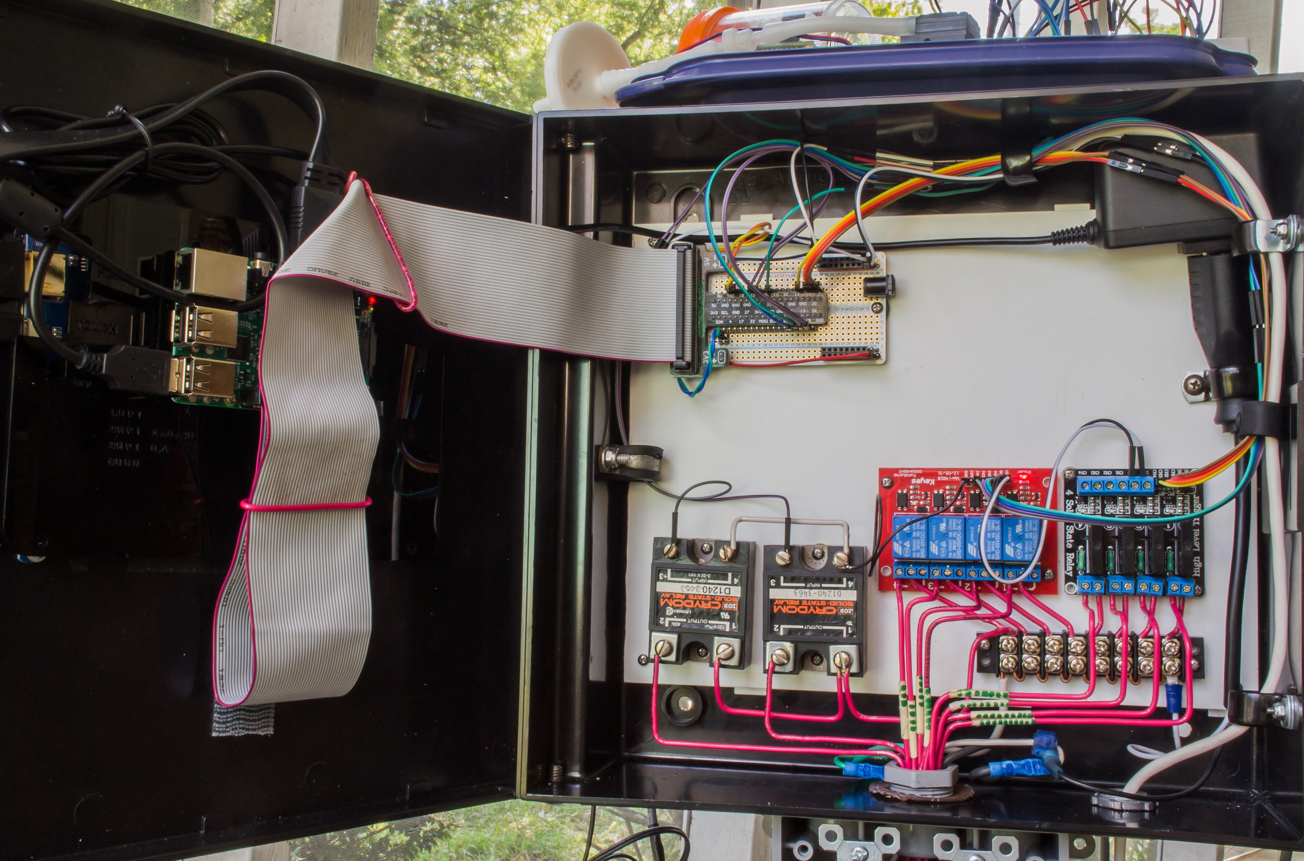
In the electrical box, power was distributed through a terminal block with all the terminals linked. Each of the 10 relays were connected to each outlet and are now individually controllable with the Raspberry Pi. All boards and relays in the box were fixed to a white piece of plastic from a broken flatbed scanner and cut down to size. The metal ring securing the electrical outlet array is a sprocket lock washer that outlived its safe use on a motorcycle of mine.
Communication to the Raspberry Pi was accomplished with a breadboard-style perfboard and an IDE cable breakout, soldered together. The power rails were just a bit too wide for the perfboard but after some coaxing, everything aligned nicely. This perfboard has the same latitudinal and longitudinal connections as a breadboard, making expanding connected devices a bit easier.
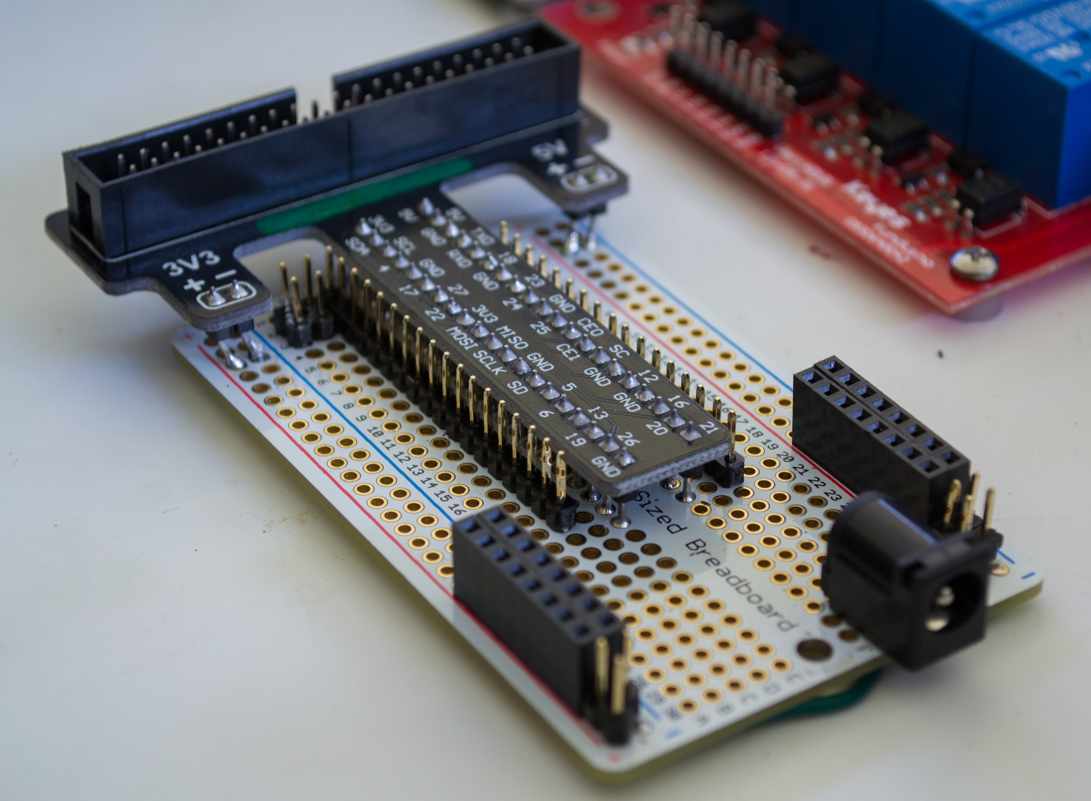
Top left: Raspberry Pi IDE/perfboard
Bottom left to right: 2 Crydom D1240 solid state relays (40 amps each), 4 mechanical relays (10 amps each), and 4 solid state relays (2 amps each).
Everything wired and powered up. The wall wart powers the Raspberry Pi and the LCD touch screen. Sensors either connect through the ethernet port on the left side of the box (behind the IDE cable), or from the opening in the bottom-right, The ethernet connection currently carries ground, 3.3v, 5v, I2C lines (data and clock), and Tx/Rx (for CO2 sensor). The 8th wire is currently unused.
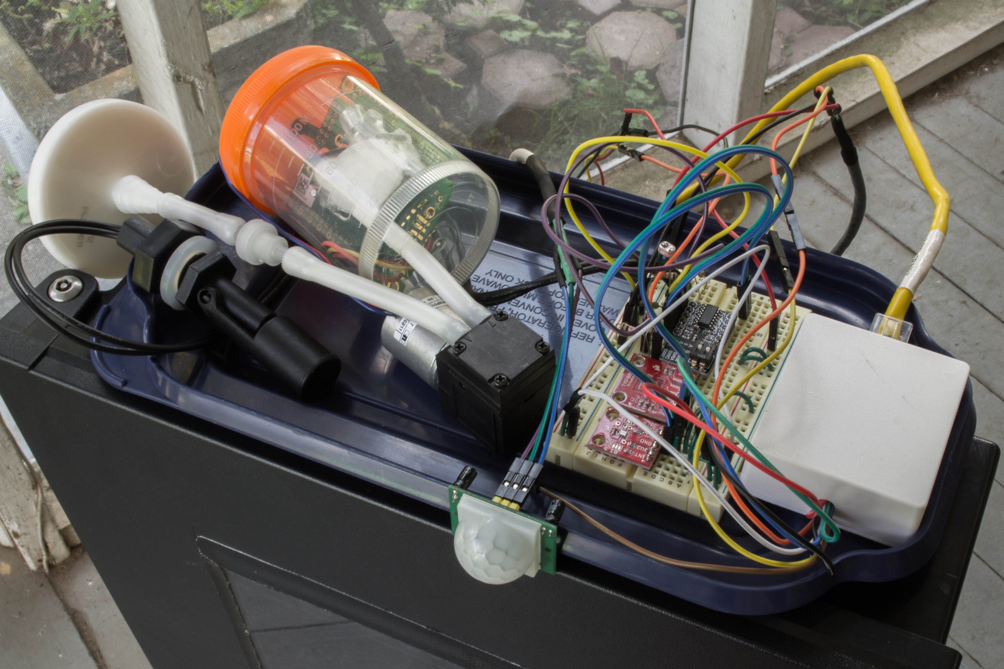
Even thought the ethernet connection permits a long distance between the head unit and sensor array, I currently have most of the sensors sitting in a tray on the top of the box while I prepare to set the system up for live use.
The pipe fittings that make up the temporary stand actually provide a nice amount of holds for organizing wires. Black is power, white is the motion sensor, yellow is I2C and Tx/Rx, and grey is the CO2 sensor.
That's all for this weekend. Perhaps the next update will have Mycodo growing or cooking something.
I'd like to thank everyone who has supported this project. Mycodo was recently selected from the Automation round of the Hackaday Prize to be 1 of 100 great projects judged in the final round.
Discussions
Become a Hackaday.io Member
Create an account to leave a comment. Already have an account? Log In.