 Kyle Gabriel
Never underestimate the potential for the human element to cause catastrophic devastation, or at least cause you to find yourself with a flaming pool of molten metal burning through your tabletop.
I had spent a good part of this weekend tuning a PID controller to heat an open pot of water to 50°C. This will be used for a cooking method known as sous vide, which translates to "under vacuum." This refers to the traditional vacuum bag that the food (which is commonly meat) is put into to increase heat transfer from the water to the food. It relies on using a temperature-controlled water bath to cook the food to a precise temperature. This method also makes it virtually impossible to overcook (which is easy to do on a stovetop or grill) and enables cooking a rare or medium-rare steak as easy as setting the temperature and letting Mycodo do the rest. Because the temperature is regulated, foods can be cooked for extended times, such as hours or days, to attain your desired tenderness. Some of the most delicious foods I've tasted have been made with sous vide, and I'm excited to be demonstrating the tuning I went through to get my sous vide system up and running.
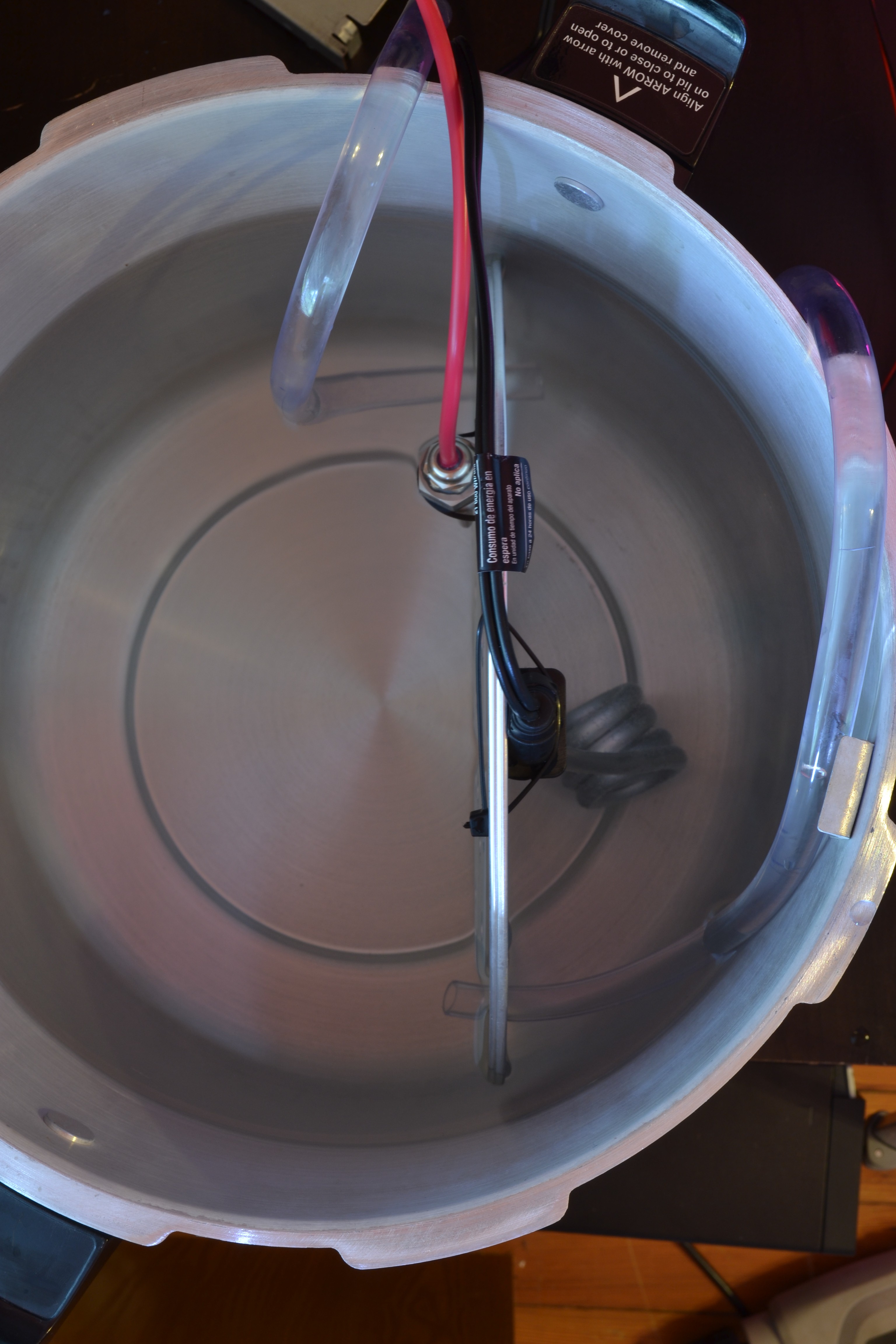
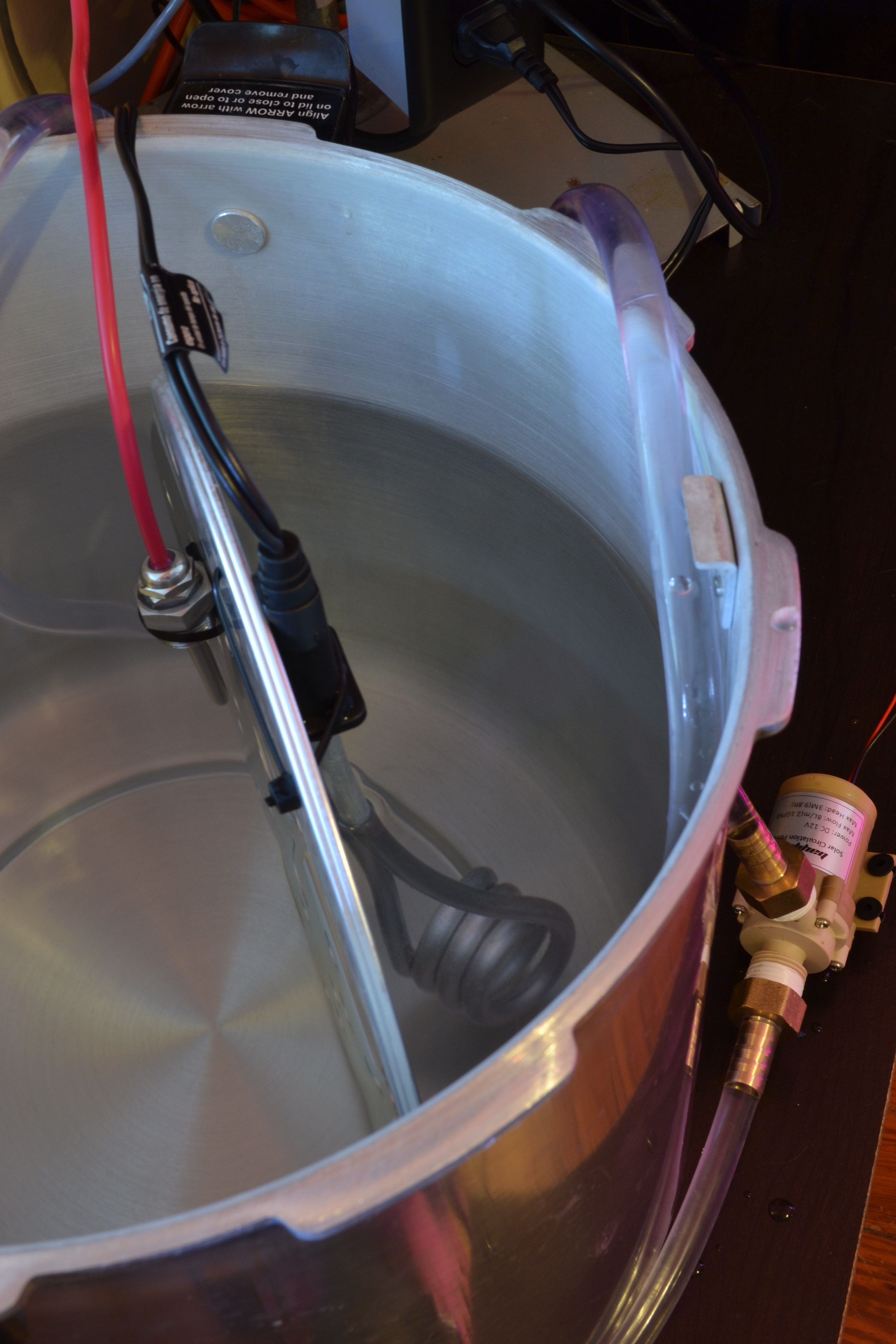
I had a submersible 120-volt AC heating element, my new Atlas Scientific PT-1000 temperature probe, and a hot water pump. I secured them all to a metal screen and began my long journey of tuning.
To begin tuning a PID, you have to understand some PID theory. I've covered this in the Mycodo manual and other things I've written in the past, so hopefully this explanation can improve upon my previous works by illustrating what I'm talking about with actual data and graphs I obtained from tuning this PID over the past two days.
First, lets discuss some terminology. PID stands for Proportional Integral Derivative. Each word describes a variable that contributes to processing an output value, called the manipulated variable (MV), from an input value, called the process variable (PV). All three P, I, and D variables are summed to produce the MV (P + I + D = MV). The duty of a PID controller is to affect the PV to move to a desired position, called the Setpoint (SP). The difference between the current position and the setpoint is the error (e).
Using water heating as an example, the process variable will be the measurement from a temperature sensor submerged in the water, which at room temperature is 28°C. The manipulated variable will be the number of seconds a heating element submerged in the water will turn on for. Our setpoint will be 50°C, making our initial error = 50-28 = 22. Therefore, at a measurement period of 35 seconds (an output is created from the input every 35 seconds), the heater would be turned on for 22 seconds and off for 13 seconds. This can be referred to as the duty cycle, and in this case would be 22/35 = 62.8%. Over the period of time where this on/off cycle persists with these durations, the heater is energized 68.2% of the time. By increasing the duty cycle, more energy would be put into the system.
The minimum options for Mycodo's PID controller are period (which determines how often a measurement is taken and the heater powered), a relay to power the heater, a sensor to obtain a measurement from, Kp, Ki, Kd, and a setpoint. Kp, Ki, and Kd are three main gains that determine how much each of the P, I, and D variables contribute to the MV. The expanded equation to produce the MV now looks like this: (Kp * P) + (Ki * I) + (Kd * D) = MV. Since P, I, and D are calculated by the controller (we're going to get into this shortly), the gains determine the degree to which each variable contributes to the final MV. So, if all gains are set to 0, the output will of course be 0, meaning the heating element will not turn on at all. And if the Kp is set to 0.1 it will produce a smaller MV than if Kp was set to 1.0.
This makes it simple to use the gains to tune the controller and to enable or disable the contribution of each part of the MV calculation. If you wanted a P controller, set the Kp gain to a non-zero number and keep Ki and Kd at 0, If you want a PI controller, set the Kp and Ki gains to a non-zero number and set Kd to 0, and if you wanted a full PID controller, set each gain to a non-zero number. PI controllers are the most common controller found in industry, as they're proven to be very simple to tune and work well in a broad range of situations (and most industrial regulation systems are simple by design).
Proportional
The proportional accounts for present error in the system. If the error is 22, the output will be 22. If we turned the PID controller with Kp=1, Ki=0, and Kd=0, the output will be 22 (and if Kp is doubled so Kp=2, then the output will be 44). In this scenario, MV will be turning a heating element on and heating the water for this duration. At the next sensor measurement, the temperature will most likely be higher. If the new temperature is 30, the new error would be 50-30 = 20. That's 2 seconds less than the first duration. You can see that the output is proportional to the input, and as the measured temperature rises closer to the setpoint, the heating element turns on for shorter periods of time. Eventually, if the measured temperature reaches the setpoint, P will be 0, and the heater will not turn on at all. Using P alone can cause problems in some systems, by not being able to put enough energy into the system to bring the PV to the setpoint or causing wild oscillations of the PV to rise above and below the setpoint instead of a steady regulation. To alleviate these issues, the I and D can be introduced to the equation.
Integral
The integral accounts for past values of error. If an error is no longer decreasing after the PID has been running for a while (meaning the temperature is never reaching the setpoint), the I will begin to increase, causing the output to increase. This can occur when the P value alone does not output enough to cause the PV to reach the setpoint and is due to the nature of the proportional variable approaching 0 as the error approaches 0. If little or no energy is going into the system, the temperature will begin to drop as the energy is dissipating from the system faster than it's being put in.
Derivative
The derivative accounts for future values of error based on the current rate of change. If our P value alone is not enough to cause the PV to reach the setpoint and the Ki gain must be turned up, this will cause the MV to increase over time until there's enough energy being put into the system to cause the temperature to begin rising again (as long as the duty cycle is not already at 100%). As the MV approaches the setpoint, the the P value may be set too high or the I value may not react quickly enough to lower the MV to prevent pushing the temperature above the setpoint, overshooting our target temperature. The D value takes into account the projected PV and compensates when it predicts it may overshoot the setpoint. Often an D value is negative in order to counteract the effects of P and I.
For this specific setup, a temperature measurement (PV) will be taken and the PID output (MV) will be calculated every 35 seconds. I will show a series of graphs showing a segment of 2 hours, with the water temperature as a teal line, the setpoint as a red line, and the duration the relay turns on every 35 seconds as green vertical bars.
Initial Tuning
Kp: 0.5, Ki: 0.01, Kd: 0
You can see that there is considerable overshoot of the setpoint, as the temperature continues to rise well past our desired temperature. I want more power initially into the system to rise the temperature faster (more Ki) and I want a faster decrease when it's projected to overshoot the setpoint (add Kd).
Tuning 2
Kp: 1.0, Ki: 0.1, Kd: 0.01

There's now considerably more energy going into the system at the beginning but the increased Kd did not adequately counter the sheer amount of Ki that's being applied. Let's increase the Kd.
Tuning 3
Kp: 1.0, Ki: 0.1, Kd: 0.1
Adding Kd had virtually no effect. I was about to increase Kd more and test again, but in my intermediate research, I came across a part of my PID code that needed review, known in my code as the integrator. This is the I in the above MV equation, and changes in response to the past rate of change. If left unchecked, this value can grow extremely large (as seen by the yellow line in the figure below), and make counteractions difficult. The yellow dotted line represents the hidden actual PID output, caused by an unchecked rise of I.
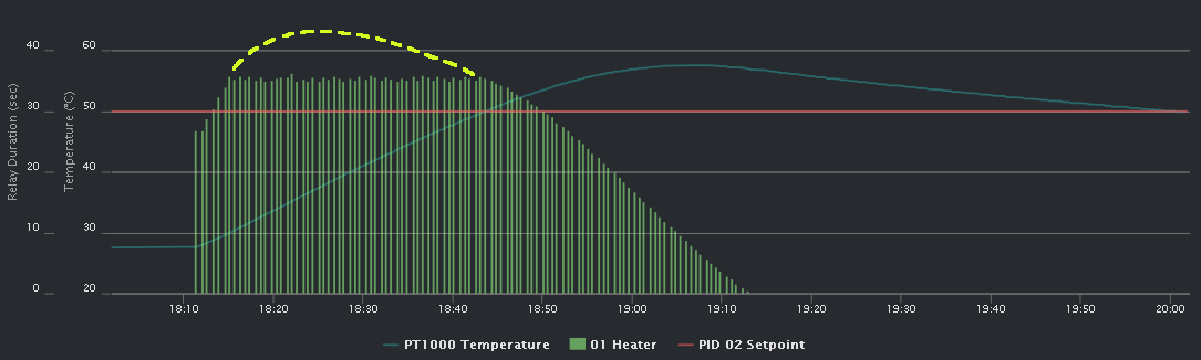
Let me note that you don't see the relay duration reaching this actual number in the graph because we are working with periods of 35 seconds and are at a maximum duty cycle of 100% when the output duration is 35 seconds. Essentially, if the next period comes around and the relay is set to be on for 90 seconds, it will stop it, log how long the relay was actually on for, (35 seconds), then start it on again for 90 seconds. In 35 seconds, this cycle repeats. That's why you will can only see a maximum duration which is less than or equal to your period. You just simply cannot go higher than a 100% duty cycle.
The solution this issue was to add limiters to the I value. That means setting a maximum I value of 100 and a Ki of 0.1, our maximum contribution to the total PID output from I can be = 100 * 0.1 = 10. After changing the code, I set the initial maximum I value to 100 and let the next test fly.
Tuning 4
Update Mycodo, add integrator min and max options
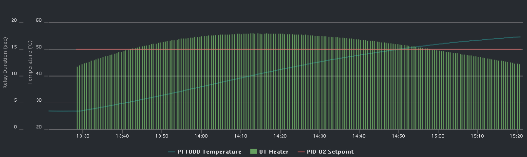
Kp: 1.0, Ki: 0.1, Kd: 0.1, Integrator max: 100
Now it's starting to look really good. We're still slightly overshooting our setpoint, so I'll drop the Integrator max to 60.
Tuning 5
Kp: 1.0, Ki: 0.1, Kd: 0.1, Integrator max: 60
It's at this time there was an incident that could have burned down my house, if I didn't notice and take immediate action to prevent it.
To carry out my experiments quickly, at the end of each run, I would turn off the PID and replace the hot water with cold water in order to immediately begin the next test. After the water was hot and the experiment had ended, I turned the PID off, took the heating element out of the water, and took the pot into my kitchen to refill it with cold water, as I've done several times prior.
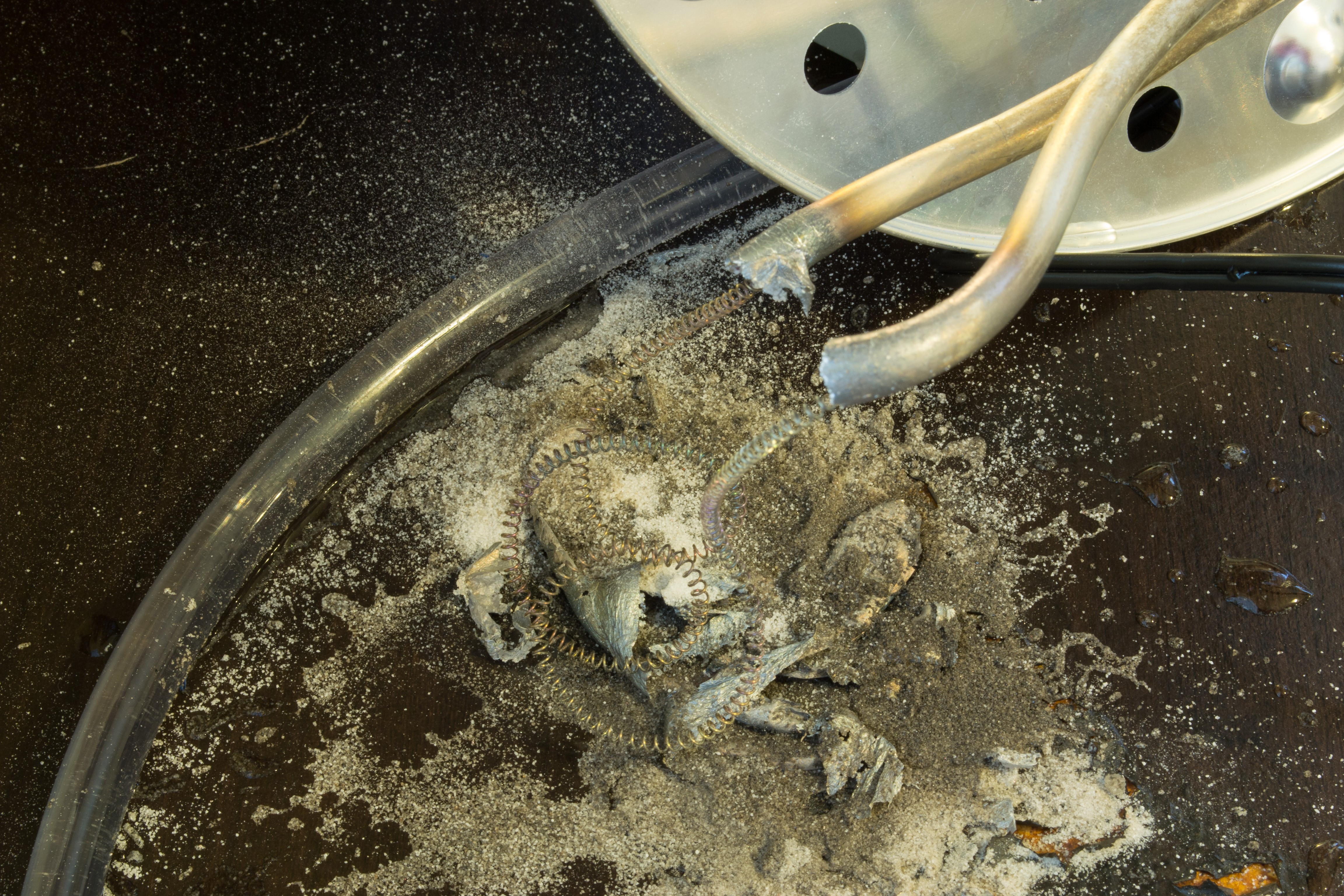
When I returned with the pot of cold water I immediately knew something was awry, because when I left the room there most definitely was not a pool of red-hot molten metal on my cheap Ikea table, with black smoke billowing toward my ceiling.
I unplugged the heater and looked around for something to put out the flame. Not immediately seeing anything and needing to act quickly, I decided it was small enough to just blow it out with my breath. Who would have known I had actually been preparing for this moment my whole life, with each new childhood birthday party and having to blow out an ever-growing number of lit candles.
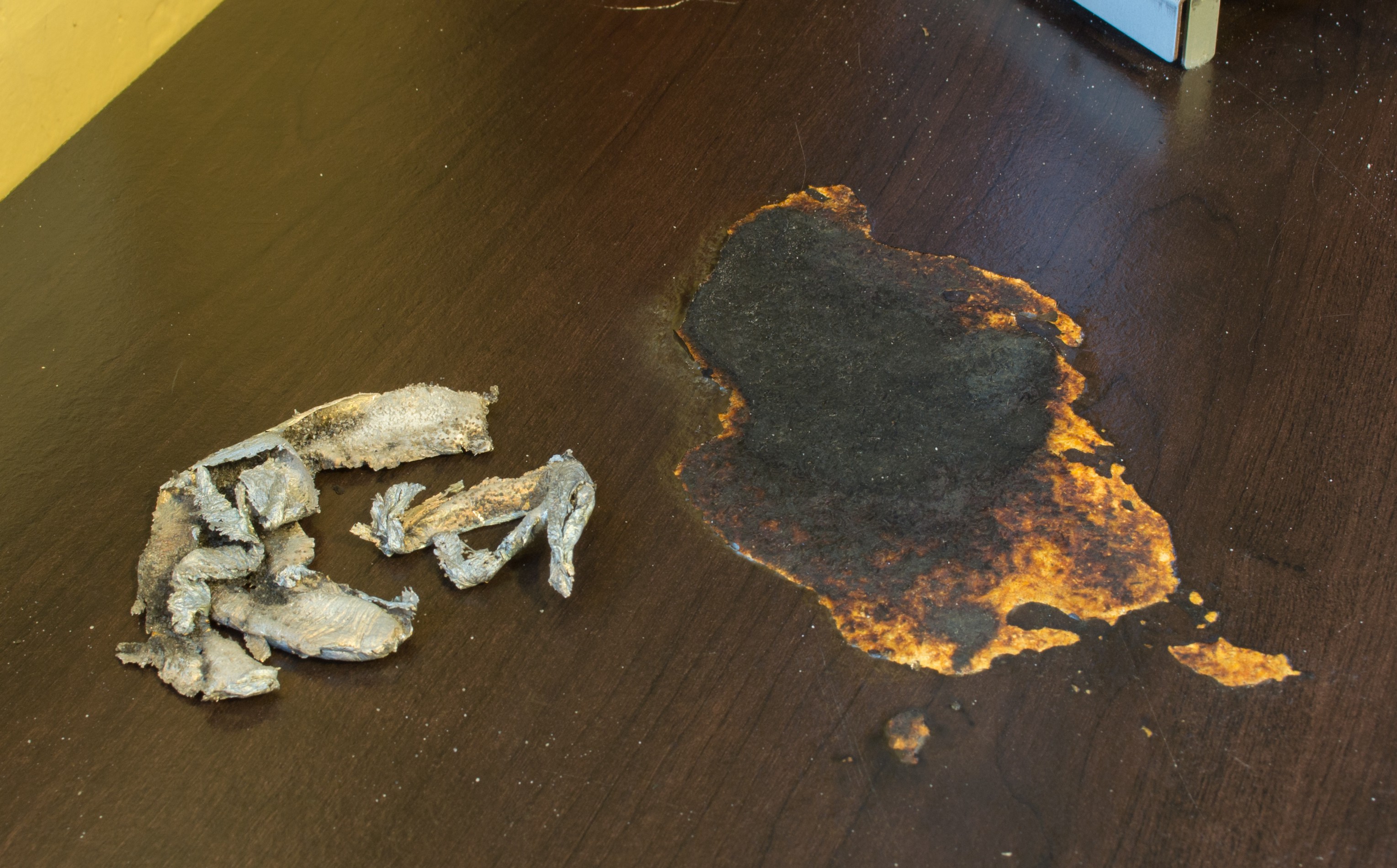
After a few hardy lung-fulls, the flame was out, and I could almost breathe a sigh of relief. However, there was still the threat from the liquid magma still burning through my cheap fiber board and plastic-topped table that was releasing a huge plume of noxious smoke. I remembered I had carried in gallons of cold water that was at my feet. Pouring this amount of water would have been overkill and difficult to control. It only needed a few dunkings of my hand into the water and letting it drip over the metal to cool it down sufficiently. Here's the aftermath.
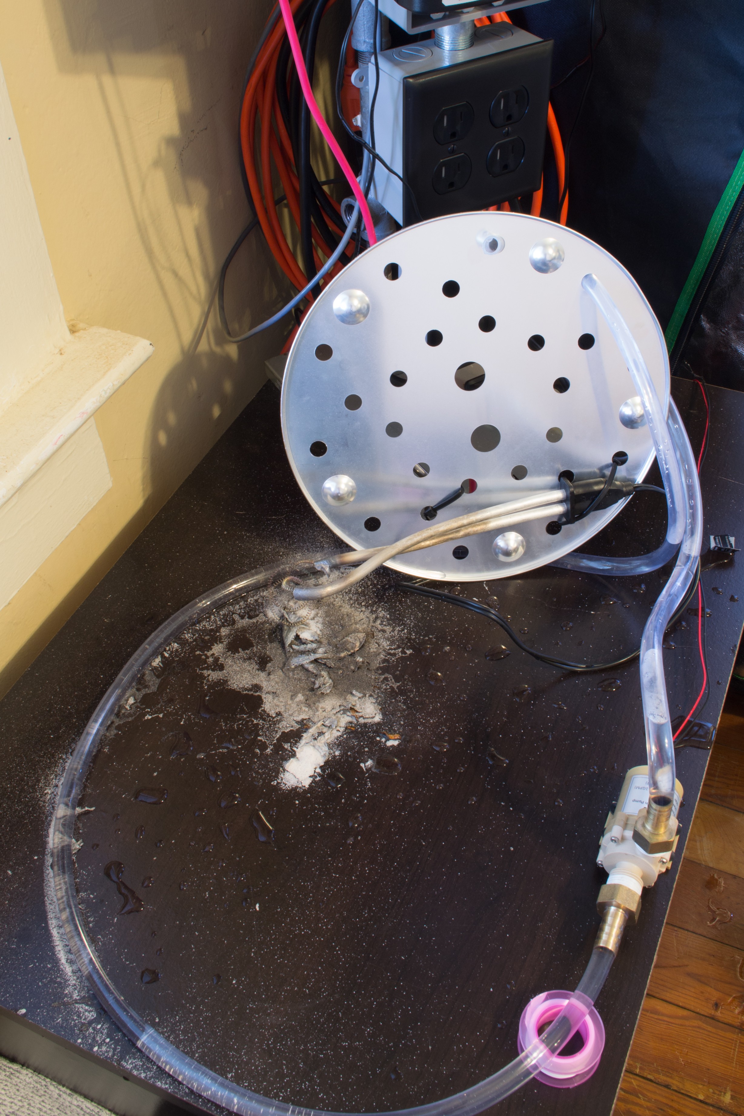
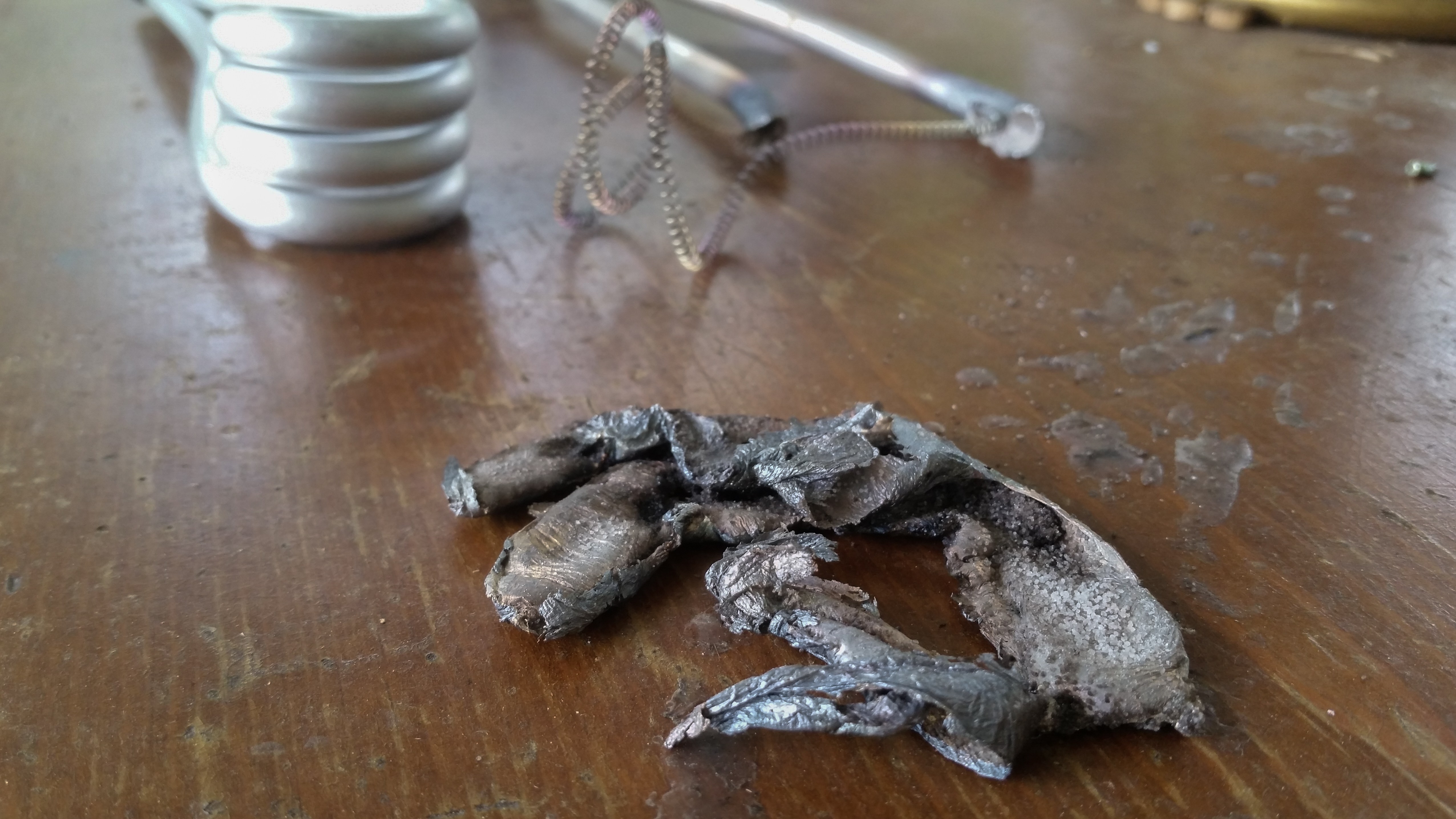
Here's the pile of melted metal and sand that was packed around the inner coil. Sand is everywhere from blowing out the flame.
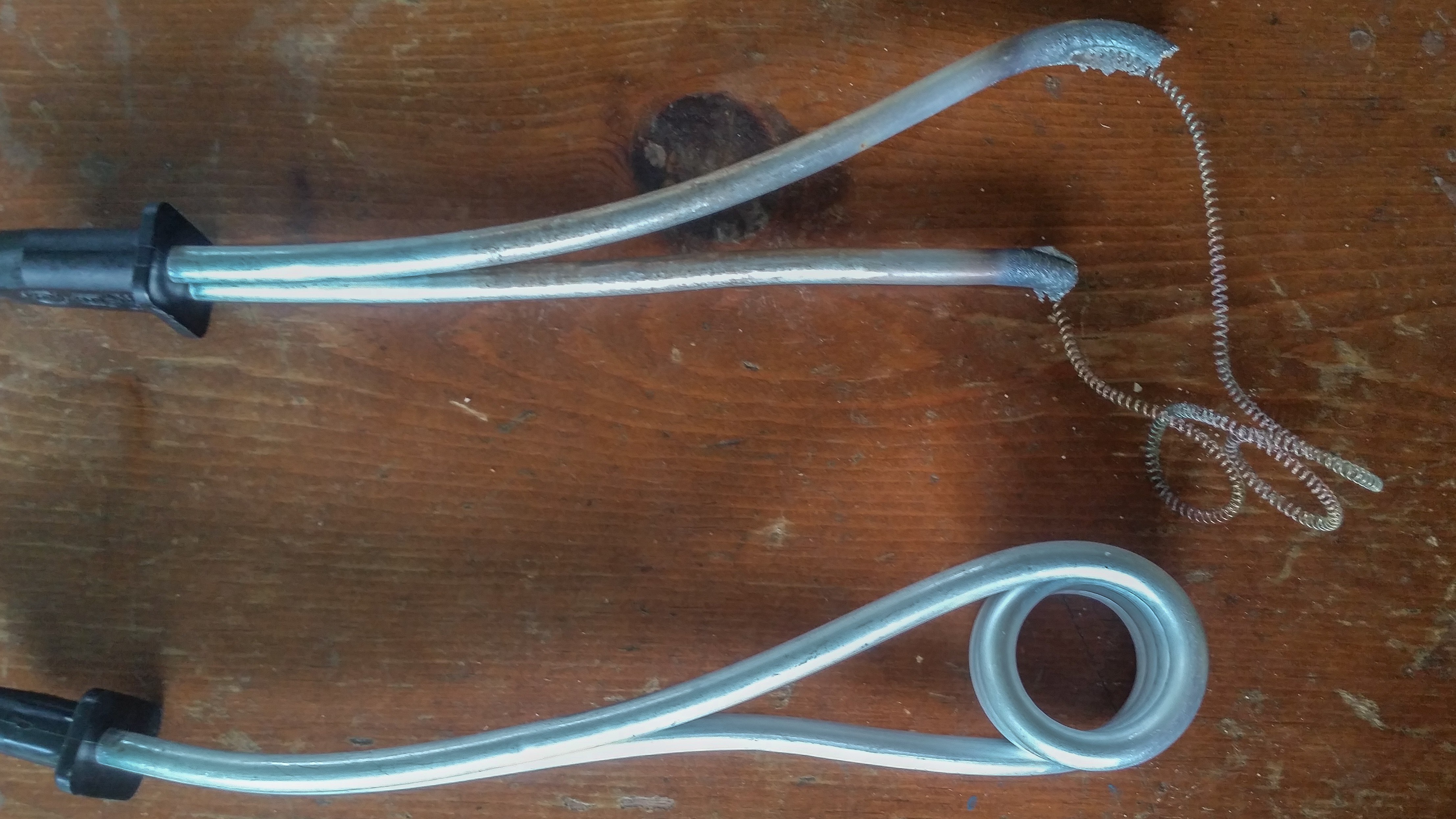
And here are some images to give you an idea of what the coil looked like originally.
So, what was to blame? Only myself.
Out of habit, after changing the PID settings, I mistakenly turned the PID controller back on, instead of waiting until I returned with the cold water! I pulled the element out to rest on the table and left the room with the pot of water.
Luckily I was in the house and found out a few minutes after it happened. The element was suspended in the air, so it wasn't going to cause any more harm after the metal surrounding it melted, but the molten metal that had fallen from it had started a small fire that could have grown larger.
If there's anything that can be learned from this incident, it's 1) be careful when using devices that have the potential to burn down your house or cause injury, and 2) invest in a higher quality heating element- one that would have just glowed red instead of causing a meltdown. I was fortunate this time but my cheap wooden table was not.
I took some photos and cleaned up my mess. Either because of similar past experiences or premonition, I had purchased two of these heating elements. Therefore, my experimenting could continue.
The setpoint wasn't quite being reached as quickly as I wanted, so I increased the Integrator max to 80.
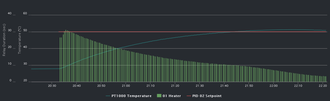
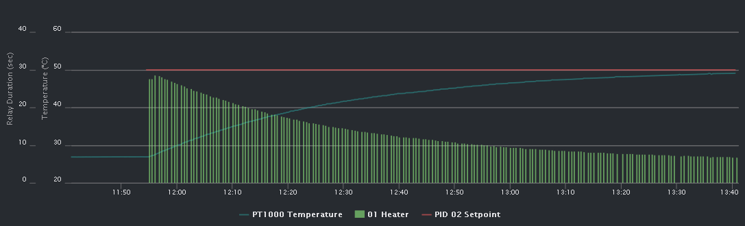
Tuning 6
Kp: 1.0, Ki: 0.1, Kd: 0.1, Integrator max: 80
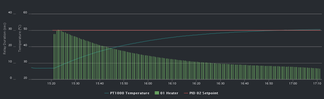
Finally, after the 6th 2-hour run, I was able to achieve a quick rise to the setpoint, with no overshoot and very little oscillation in order to maintain the temperature.
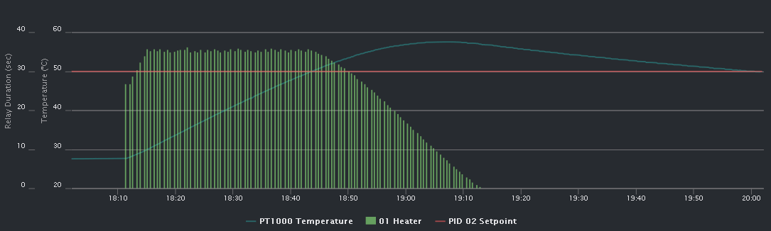
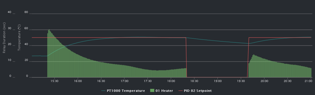
This last graph demonstrates how this PID tuning is efficient at regulating from another starting temperature. I turned off the PID to let the temperature fall, then turned it back on. See the results for yourself.
Besides from the minor setback, the sous vide PID tuning was a success, and I'll hopefully be enjoying a perfectly medium-rare ribeye steak tonight.
Discussions
Become a Hackaday.io Member
Create an account to leave a comment. Already have an account? Log In.