 Johannes Hassler
A common task in robotics is to create rotational motion with high rotational resolution and/or high torque on the output side.
A strain wave gear is the ideal solution for this.
High Torque Capacity - The power is transmitted through the engagement of multiple teeth and it offers high output torque capacity equal to drives much bigger and heavier. Single-Stage High Reduction Ratio, (nearly) Zero Backlash and an In - Line Configuration, as the gearing input and output bolt circles are concentric, allowing machine designers to reduce the required packaging space compared to other high ratio, high torque drives and High Torsional Stiffness.
There are several issues for development teams to use them in their design though.
Depending on ones budget it is not justifiable to buy off the shelf parts and many current 3D printable designs use flexible filament what may need to be ordered and is more complicated to print.
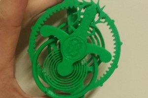
Here comes my design to the game: with all custom parts 3D printed with PETg, a user needs to only master one set of Parameters on his FDM-printer to build this gear all by himself.
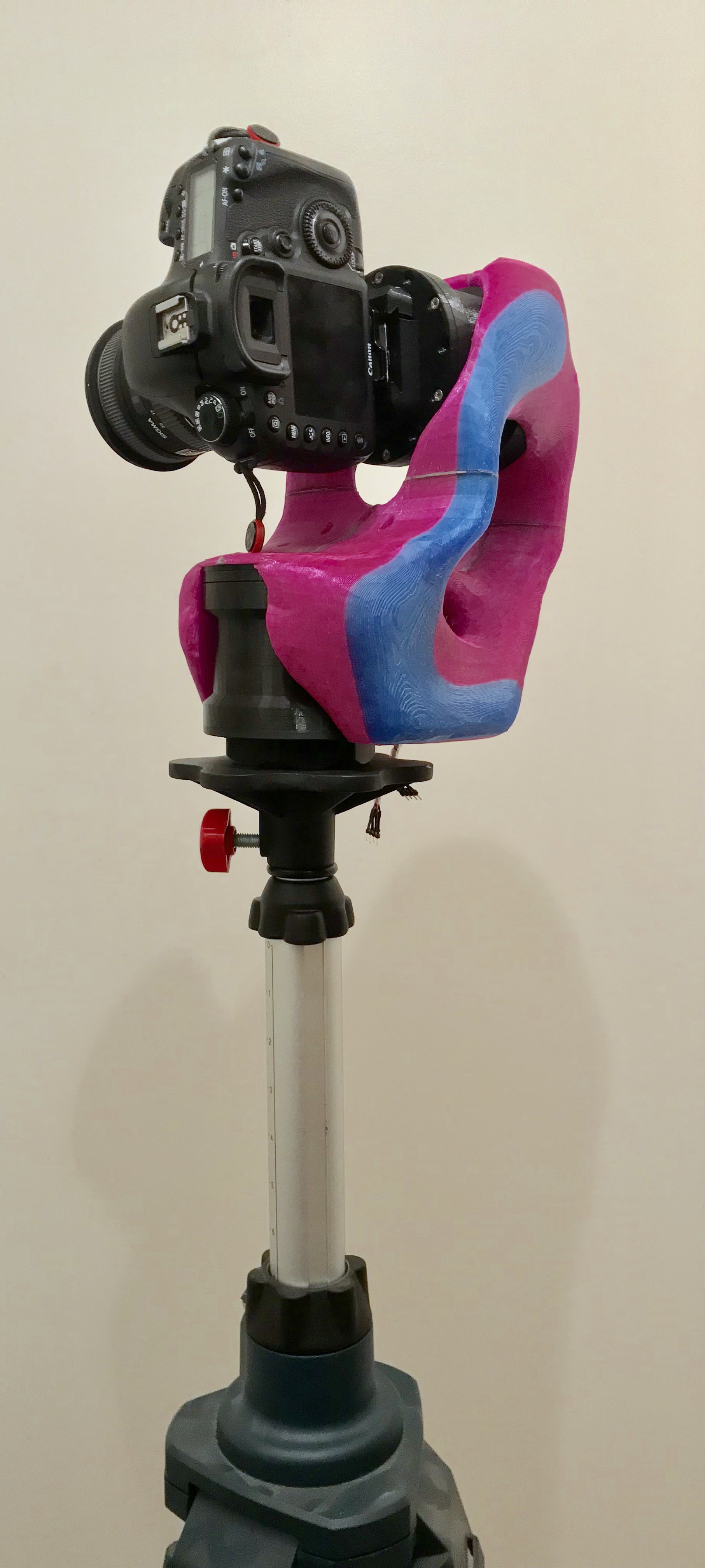
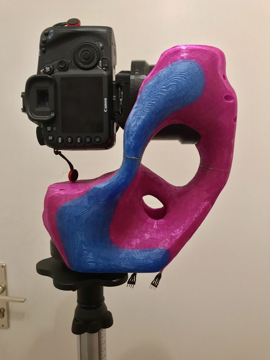
Another unique point in this design is that the gear itself is the housing for the motor - input and output sides are flush and can be mounted anywhere.
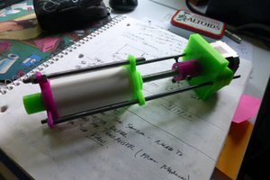
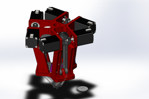
I have now 3 prototypes of this gear and some points to fix before call it ready to use for everyone:
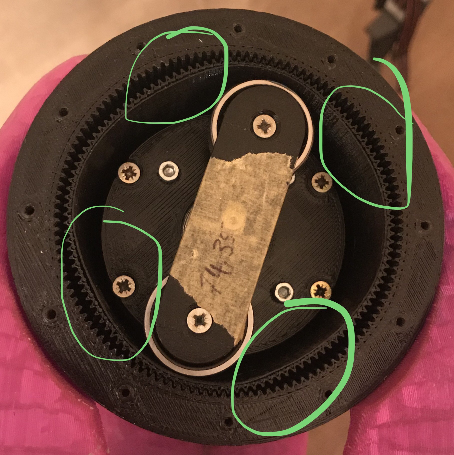
- The backlash of the part is still there - the culprit my be the triangle shape of the teeth. A more trapezoidal shape with steeper angles might reduce it further.
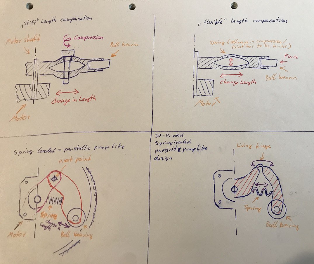
- The stiff rotor has to be printed to the correct size - a design with the possibility to correct its length could prevent reprints and shorten the time used to fit it all perfect.
- A stiff rotor also has problems with deviations from the right diameter - some kind of flex could prevent the motor from stalling if there is a little bump in its way.
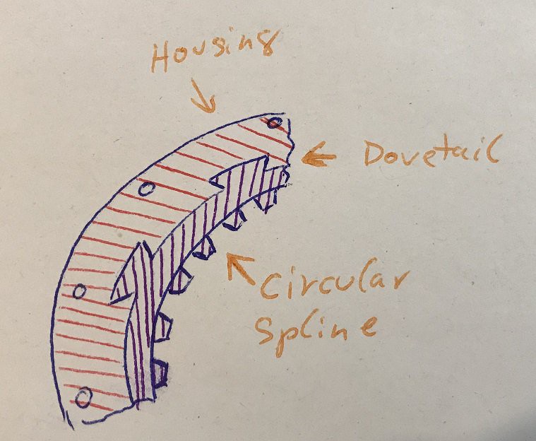
- If you want to change the gearing ratio you have to reprint the biggest parts of the design - the cup and the housing. Some sort of exchangeability in the housing would make iterating much faster and cheaper.
 doctek
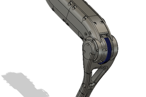
 David Brown