Disclaimer: I am an RF engineer by trade and a hardware (mechanical + electrical) engineer by hobby, so software is not my strong point! I am hoping to make a simple and easily obtainable/buildable hardware platform that is open source and allows others to tinker with and add software features to.
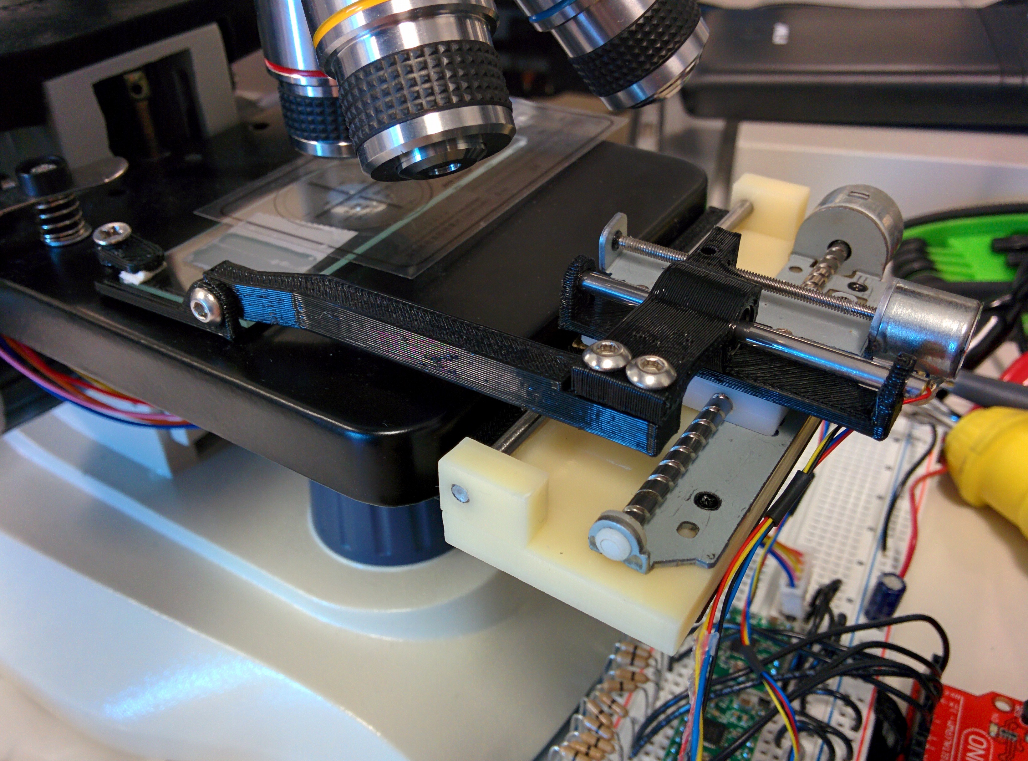
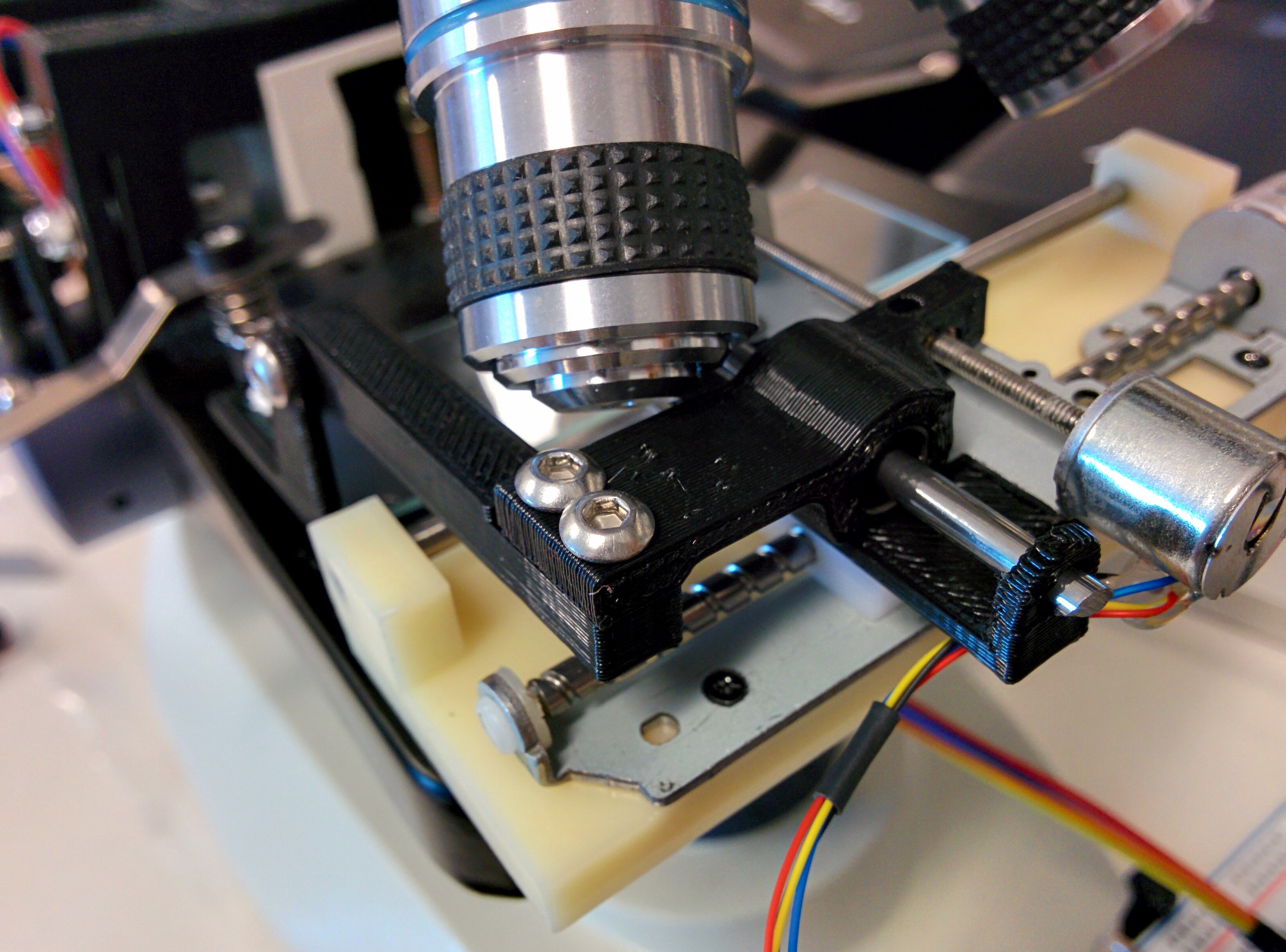
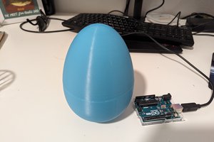
This project started when I was tired of looking through a narrow eyepiece of my cheap microscope, and decided to add a cellphone mount to take high quality photos/videos. I then realized I could use it with the live streaming software that I use when I go on vacation or to check who's at the front door, and stream the microscope view to Youtube or other places and share the experience in real time. I want to take this a step further and allow web control of the slide's position and microscope focus, which will add the possibility of doing focus stacking, large panoramas (gigapixel images) and if the software was available, would allow a quick scan of the entire slide, then a minimap type view to zoom into a particular area of interest, or even tracking a moving creature with CV. My goal, as stated, is to provide simple and robust hardware to enable future software features like those I mentioned, and many more people may think of in the future. I believe this project is in the spirit of the Citizen Scientist contest by opening the door to having many automated microscope stations anywhere the world and enable scientists to view and move samples over the internet.
So far the project cost is projected to be under $200, making this relatively accessible for schools or small labs/citizen scientists.
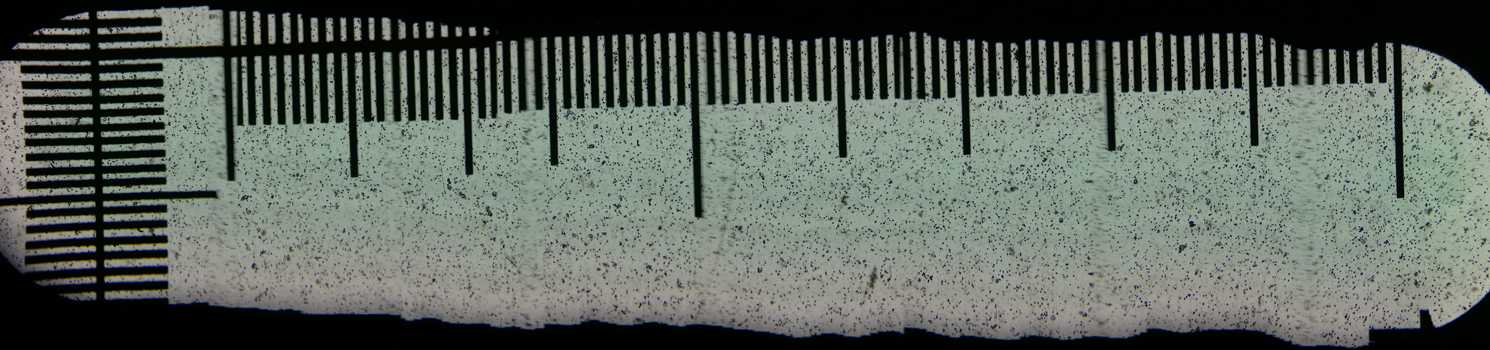
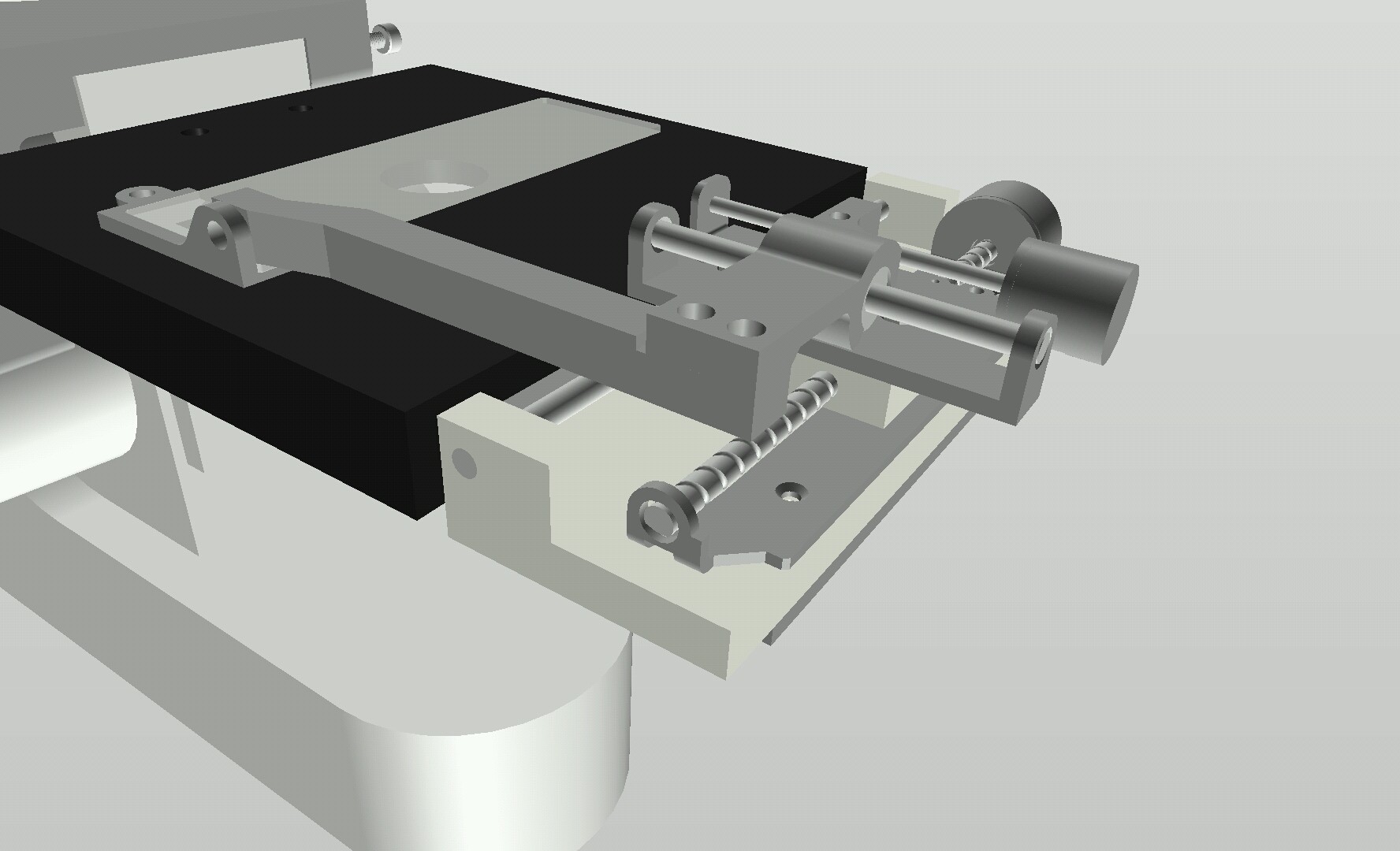
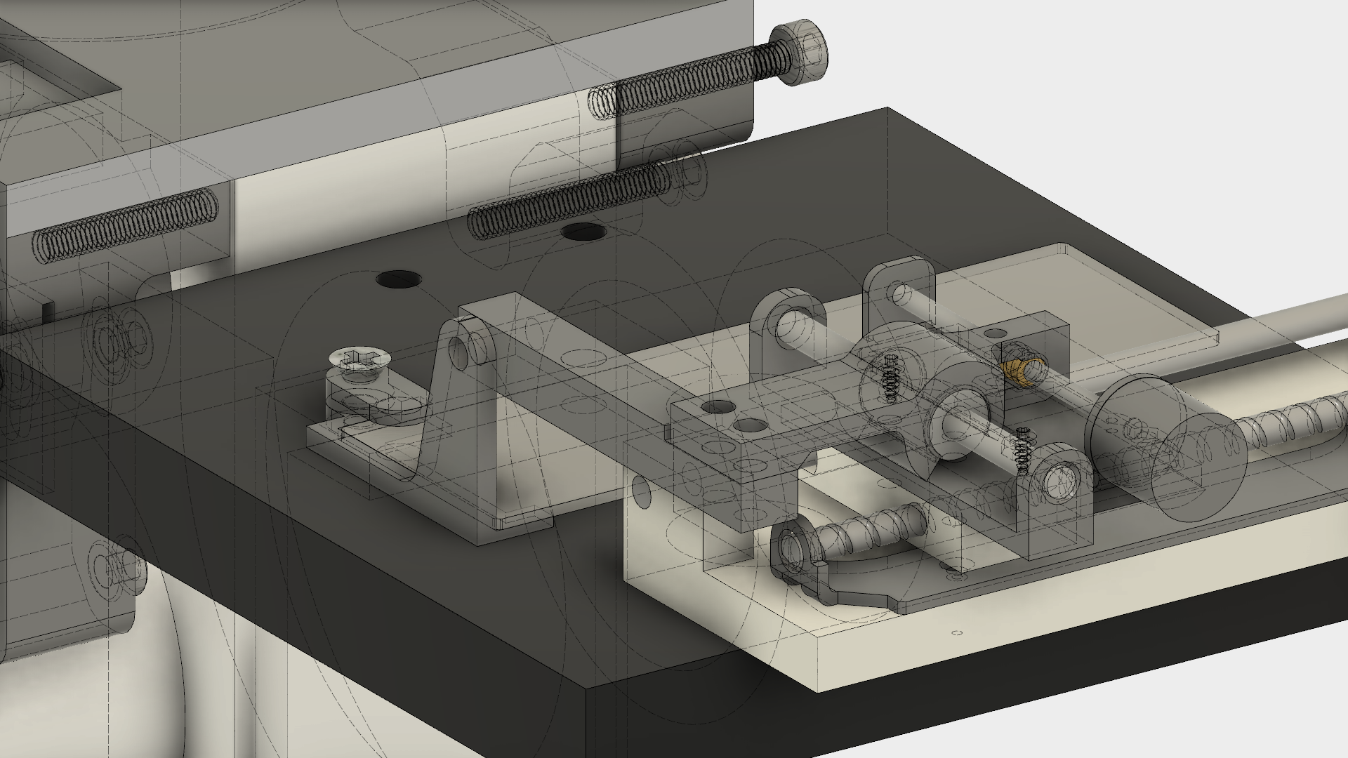
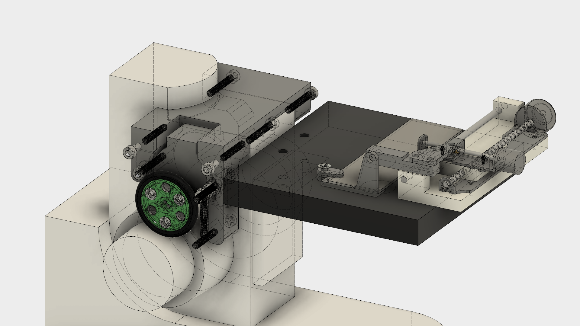
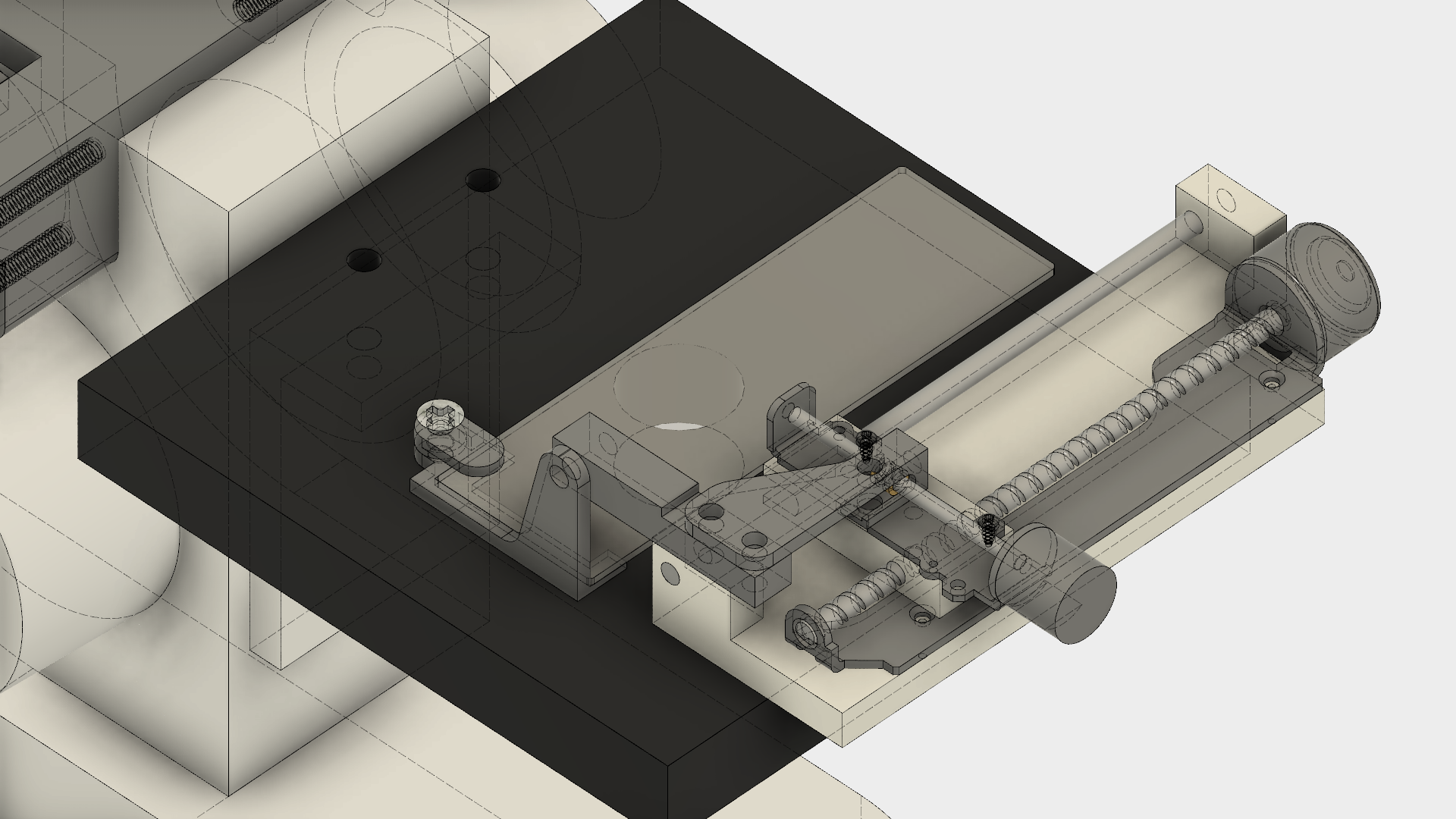
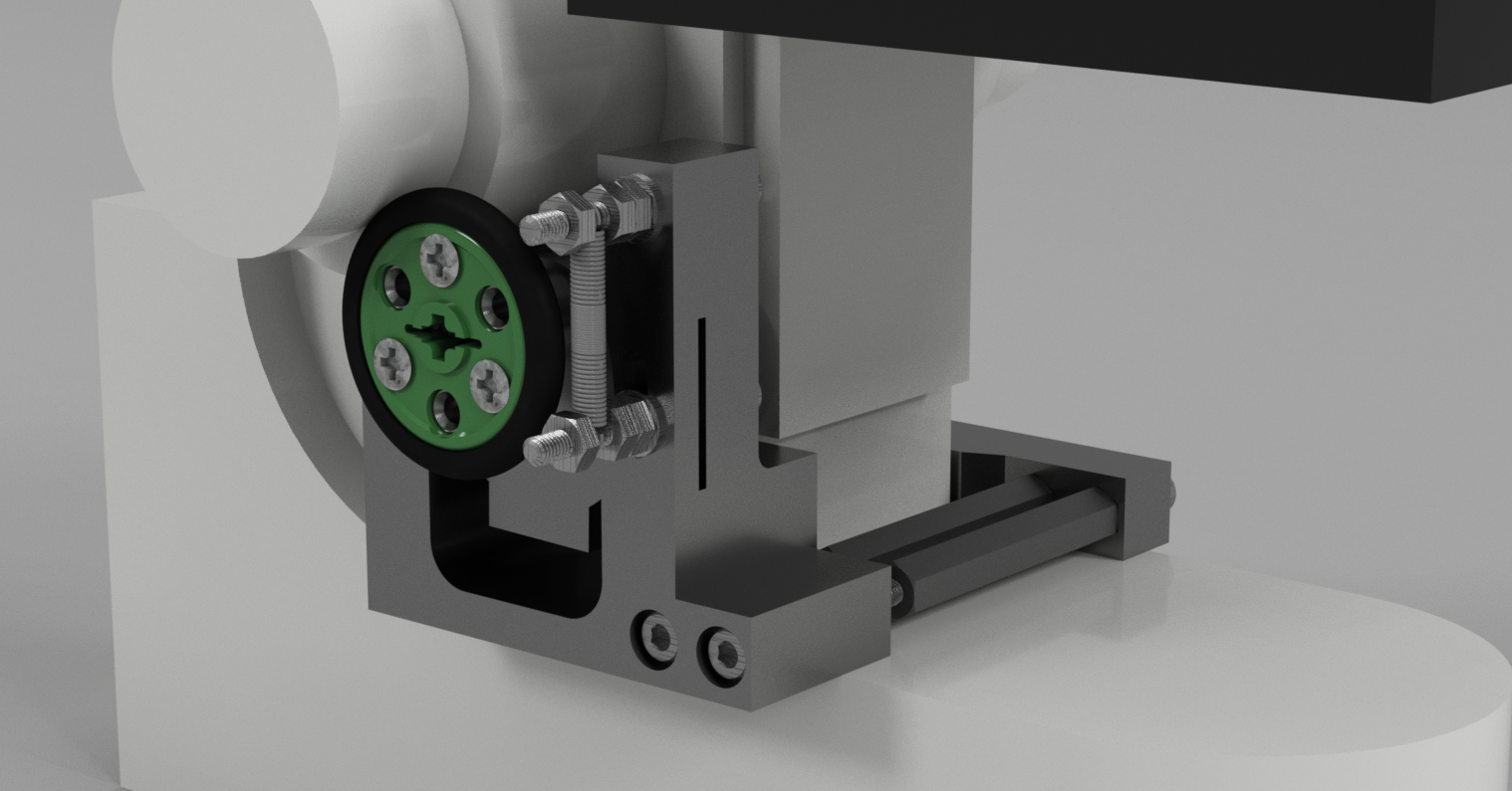
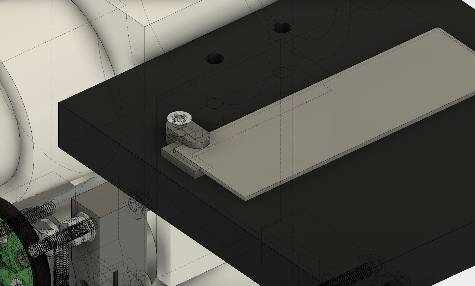
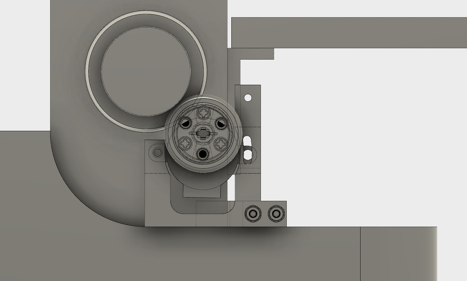
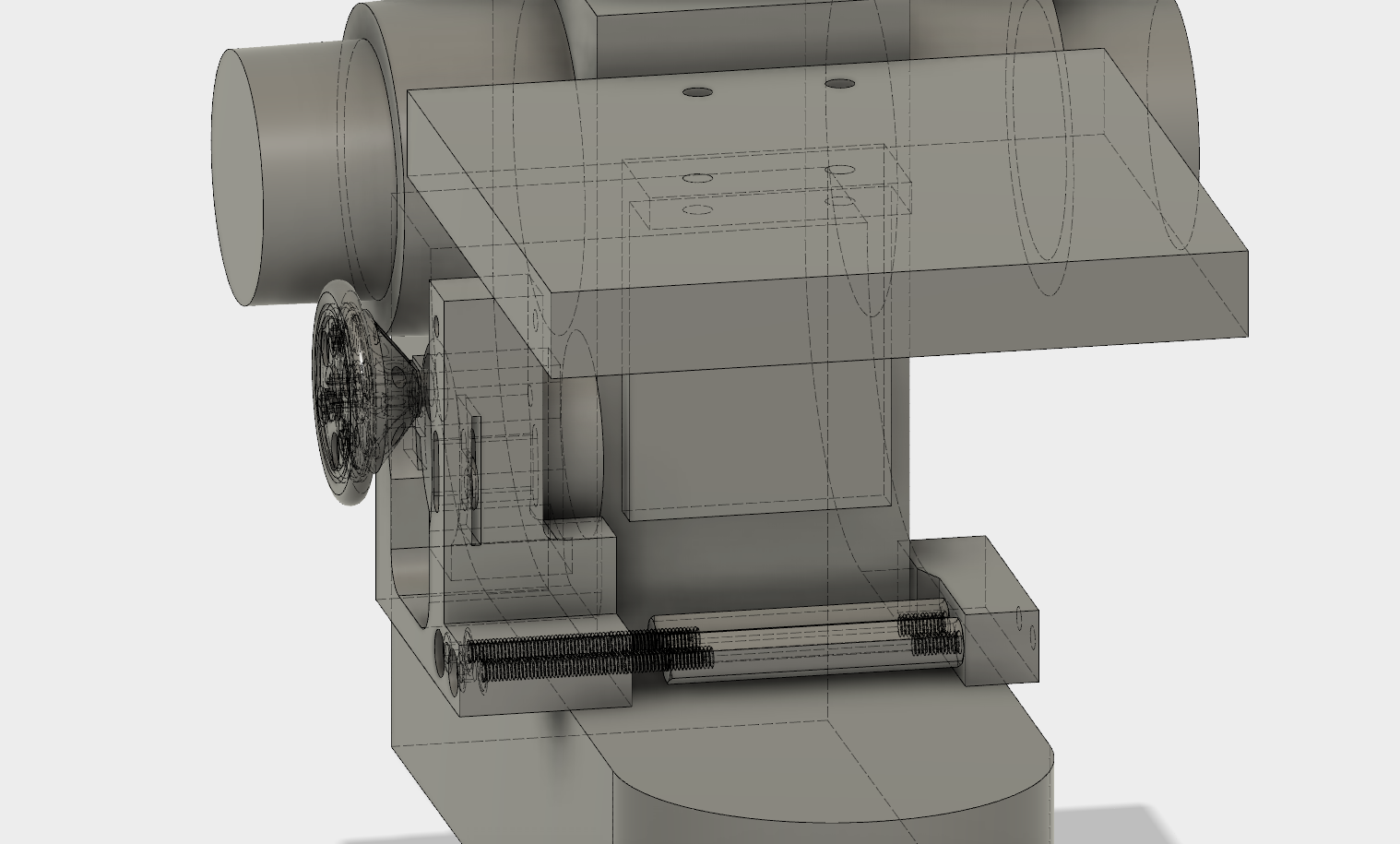
X-Y Table Specifications:
X axis range: 52.3mm, X axis precision: X.XXmm
Y axis range: 29.1mm, Y axis precision: X.XXmm
License disclaimer, Programs I will be using are as follows:
Autodesk Fusion 360 (3D CAD) - Startup license, free for companies making less than $100k/year or non-profit
Eagle MAKE Personal (Electrical Schematic/Layout) - For individual, non-commercial use
Others - Open source where possible, e.g. Arduino

 Krockwell
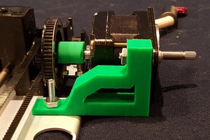
 Rocketburns
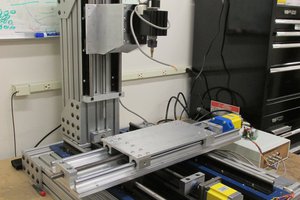
 jupdyke
Tip: It's the jankiest fix ever, but if you connect a speaker to your duino you can play a short PCM file that says "Cheese" and trigger your pictures automatically! You can also mod one of those mini bluetooth selfie buttons, or use one from a selfie stick through the headphone jack.
I like this and hope you're still doing stuff.