I came up with this circuit as a feature for an appliance timer. I wanted the ability to activate the timer outside of it's timing cycle. Say you have the timer setup to turn on the lights at a certain time but it's a cloudy day and you want them on earlier.
On most timers without fancy controls you'd need to reset the timer that may be on the floor, under a chair, etc. But what if you could just toggle the switch on the light (turn off, then back on) and the timer would activate? That's exactly what this circuit allows you to do.
This circuit is placed in-line with the switched AC line and can sense impedances on the AC line well over 10MΩ. It provides a TTL output indicating a closed (5V) or open (0V) circuit. What's nice about it is that it remains in-circuit without any mechanical switching and doesn't interfere with the system it's part of nor connected equipment.
FYI, the only equipment it won't detect continuity with are gas discharge tubes (e.g. Neon, etc.) since it operates well below their ionizing voltage.
Two versions of the design are included in the LTspice files included with the project: isolated and non-isolated but both are identical except for the logic output.
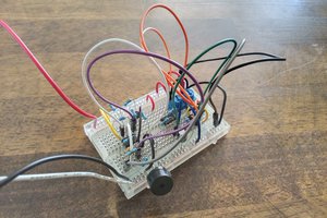
The circuit is comprised of four sections: supply, SOA protection, sense, logic. R5, D4, and D5 form a simple half-wave rectifier and shunt regulator that limits the sense voltage to 13V. This is necessary to remain below the under-volt lockout threshold of electronic lighting fixtures. Maximum dissipation is approximately 661mW. Diodes D1, D2, D3, D6 protect the transistors from exceeding their SOA when the AC line is energized. Specifically the negative half of the sine wave is blocked or removed to keep Veco within limits.
R4 serves as both a current limiter for the sense circuit and the reverse bias protection afforded by D3. The sense circuit is comprised of R1, R4 (previously mentioned), Q1, and Q2. Q1’s base provides the sense voltage to the AC circuit being measured. Current flow is amplified and Q1s collector biases Q2. Q2 further amplifies the signal to drive the LED of the opto-isolator. R6 removes stray voltage (noise) from the base of Q2 when the sense circuit is open to prevent false triggering. The logic drive is comprised of the transistor half of the opto-isolator, C1, and R3. The transistor will conduct on each positive half-cycle of the AC line sine wave. C1 smooths this to provide a stable logic high when continuity is detected. R3 serves as a pull-down resistor to a logic low when there is no connectivity. The transition time from high->low is relatively long at ~ 400mS.
 Zach Armstrong
 UTSOURCE
 Electroniclovers123