 Lee Djavaherian
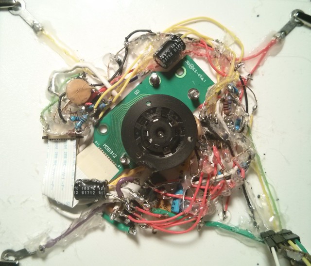
The replacement BLDC has been soldered in place on Circuit Board C, and the new ZIF ribbon cable connector seems to work pretty well. However, since I'm trying not to wire on top of the BLDC this time, I've just about run out of room for the circuit underneath the Gyrofan wheel. Dang.
The ZIF connector has about 1 mm clearance, and the larger 100 uF electrolytic bypass capacitors wouldn't fit, so I had to overlap the one for the L6234 over the BLDC board (which can be bent out of the way), and I had to move the one for the ATtiny 1634 several centimeters away, so it won't work as well as it did before.
This BLDC is giving me trouble, however. It has a different sound when it runs, stalls on slow-starts, and doesn't have as much torque as the first motor (it acts as if it is running on only two phases). The motor wiring is not the cause since I've tried every combination of hall-effect sensors and coil patterns in software to rule out a motor miswiring on my part, and the 3 hall-effect sensors are being properly detected.
So I've narrowed it down to motor drive current: it is either the L6234 circuit (perhaps the charge pump), the L6234 itself, or the ATtiny ports/wires driving the L6234. I'm really hoping that when the first motor burned out that it didn't do a full short and also burn out part of the L6234. And the ATtiny ports can also burn out if the L6234 loses its 7.4 volt supply voltage... I really hope this isn't the case.
There is another possibility that I didn't consider, though. As I've been testing the motors indoors, I've been draining the Lithium-ion batteries, and they are now around 3.5 volts each. In series, this equates to 7 volts, the minimum operating voltage of the L6234. Perhaps it is not operating efficiently enough.
So I opened up the Power Regulation box and soldered a wire to the 5v power input of the Lithium-ion charger board, which is supplied by the solar charger, and exposed this wire outside of the box in one of the wire channels between the Circuit Boxes and Battery Frame. This allows me to access the wire to bypass the solar panel in cases where I need to charge the Lithium-ion batteries during testing. There is no way to charge them when the case is closed up unless I have sunlight. Now all I have to do is open up one of the wire channel access panels.
I'll test again once they are fully charged to rule out any issues with the supply voltage.
I decided to solder the bypass wire after the solar charger MOSFET thinking that, as long as the MOSFET was off, the current wouldn't feed back into the charger--but I forgot about the MOSFET body diode, and so it fed back anyway, lighting up the solar charger LED. I'm hoping that the output stages of the solar charger's step-down converter include their own diode and this won't be a problem. I'm not going to actually use the solar panel while charging the batteries over this bypass wire, and the voltages are the same, so I'm probably okay.
So, if the battery voltage is not the problem, I will have to write some software code to pulse the coils in different patterns so that I can test them with the multimeter (but short enough durations as to not overheat the coil). The most likely cause is that, when moving the wires out of the way to make room for the new motor, I probably agitated the wiring and created a bad connection somewhere, as my solder joints are fragile.
And I also almost had a heart attack when, to my horror, I accidentally melted the plastic rotor mount of the pristine BLDC when I was soldering... *sigh* ...but what can you do. Luckily, it still fits within the Gyrofan mount, and the loss of mass was negligible.
Please excuse the horrible circuit appearance of Circuit Board C--the hot glue makes it look worse than it really is. I try to only apply hot glue to the areas that are mechanically the weakest, and I purposely leave many solder joints exposed in case I need to repair or modify it in the future.
Hot glue is actually a really neat medium to work with, in conjunction with the PETG thermoplastic, as it is one of the few things to stick to it, and it can even be shaped for some mechanical functions. It can be easily removed with pliers, hobby knife, fingernails (or by reheating it to free stuck wires). The wires look haphazard because I've had to remove and replace components a few times--the initial circuit was actually quite clean.
I literally used a 30-year old blunt-tip soldering iron to solder 90% of TRILLSAT's circuits, since I cannot find new tips for it that match the screw threads. I filed down the copper tip in the beginning of this project, but this removed the protective layer (iron, I assume) causing the tip to dissolve.
Since one of the tiny wires to the ATtiny 1634 (an SOIC-20 package) broke free when I was installing the new BLDC, I had to create a makeshift tip just to fix it without wrecking the circuit--so I wrapped a copper wire around the iron and sharpened the wire (then used my magnifying lamp to see).

It's crude and messy, but it's all I have. Blunt-tip soldering is a lost art, I tell you.
Discussions
Become a Hackaday.io Member
Create an account to leave a comment. Already have an account? Log In.