 Lee Djavaherian
A couple of weeks ago, I received a nice comment from one of the community judges for the Hackaday contests and was amazed when I also noticed that he added TrillSat to his How to Enter a Project into a Hackaday Contest page as an example of what to do to make one's project stand out (excerpt below):
"We really, really like projects that encourage citizen science, or that could be used for real research and development!
A few projects come to mind, even after the thousands of projects I've seen . . . , the TrillSat, . . . Why did these score so well? They fit their category; they were innovative or creative; they solved an actual problem or enabled science to be done; the projects were completed, and had working examples."
Thank you! I also noticed that yesterday one of the HaD writers published an interesting article on the capstan equation and capstan drive, a simple machine that is often underappreciated and core to the operation of TrillSat.
I have continued improving TrillSat since my last log entry on 9/7/2018 and have posted summaries below (hardware and software updates, bug fixes, the radio system, motor drive, gyro, and planned updates).
Some of the highlights are:
- Built secondary station TRILLSAT-G and recorded video of a successful over-the-air test of all of TRILLSAT-1's packet radio systems (including my experimental APRS "stupor" method)
- Tested the BLDC gyro at 1800 RPM (5 times faster than the original video)
- Extracted the craft's equations of motion and began writing a paper on the subject
- Designed a "camstan" to act as a continuously-variable transmission
- Added the Delta-v Motor Drive System which incorporates my mathematical model of its torque curve
The primary obstacle preventing me from testing everything outside is that tricky motor drive. By overloading a single motor to maximize the number of functions per motor while minimizing the number of sensors, I was hoping to skirt by some of the mathematical complexity of the multiple joints and links in an articulated robot, but because of the axes of rotation, the dynamic torques, and the precision that I require, I unwittingly created something similar but in rotational form. It turned out that my analogy of orbital mechanics was much closer than I had realized two years ago, which is wonderful, but it's not easy to keep the wobbly craft on my idealized "orbit", especially when it is under feed-forward, dead-reckoning control most of the time (which is why I had to build the Delta-v system).
Hopefully, I'll get a successful indoor test of the craft moving "smoothly and accurately" along the tether, two traits that are critical for both long-distance locomotion and aligning the solar panel. Whether it succeeds or fails, I plan to record video of its first Delta-v test this year.
It's difficult but exciting; my Kitty Hawk moment is near.
Hardware updates:
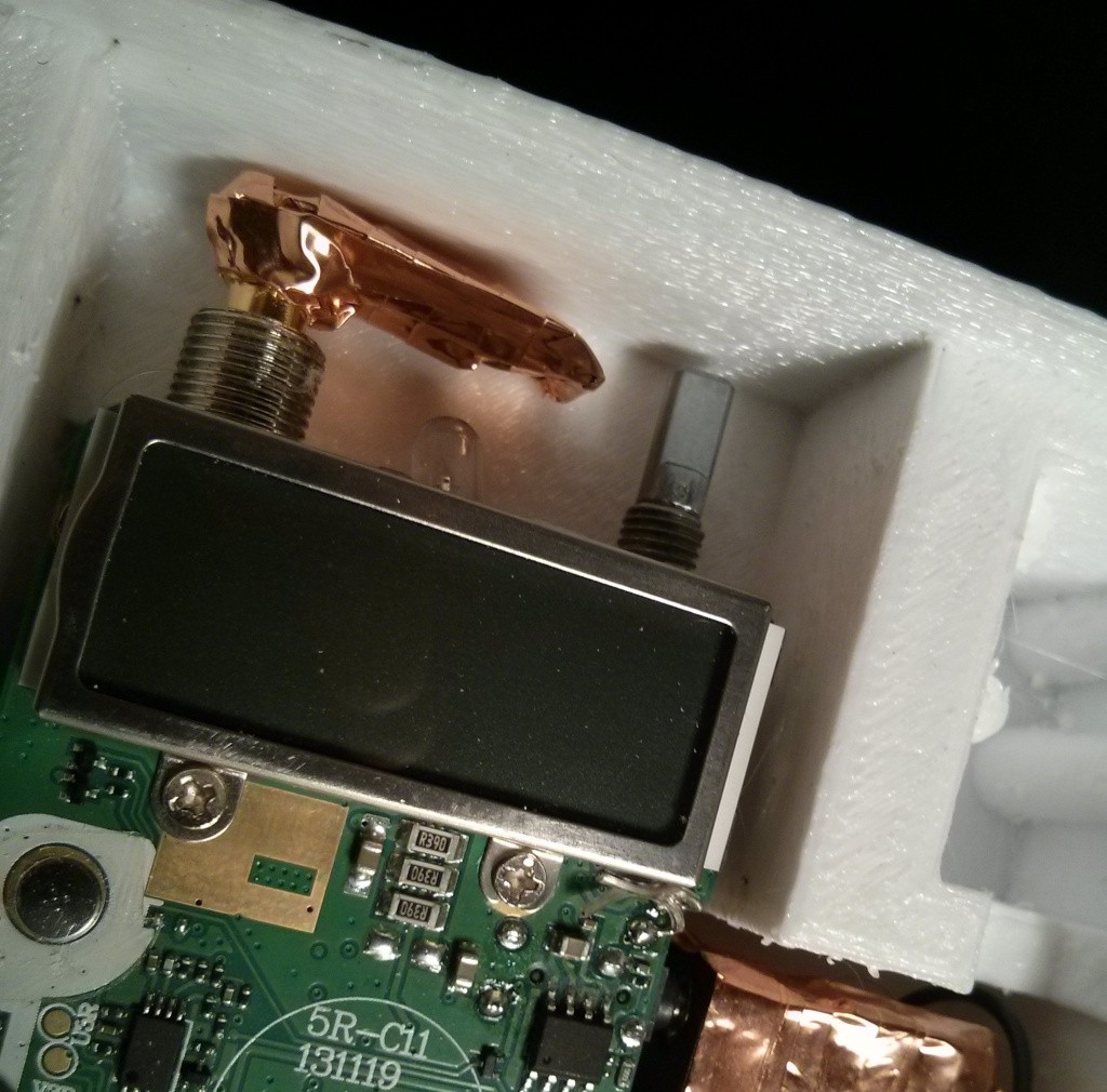
Built a low-profile 50-ohm dummy load to barely fit inside the TRILLSAT-1 radio box using two 2-watt, 100-ohm, non-wirewound resistors in parallel for 50 ohm, 4 watts to match the max output of the UV-5RA.
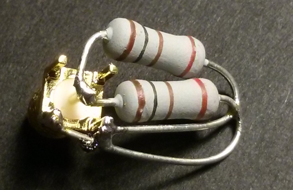
It was insulated with Kapton tape and has a copper foil shield to ground.
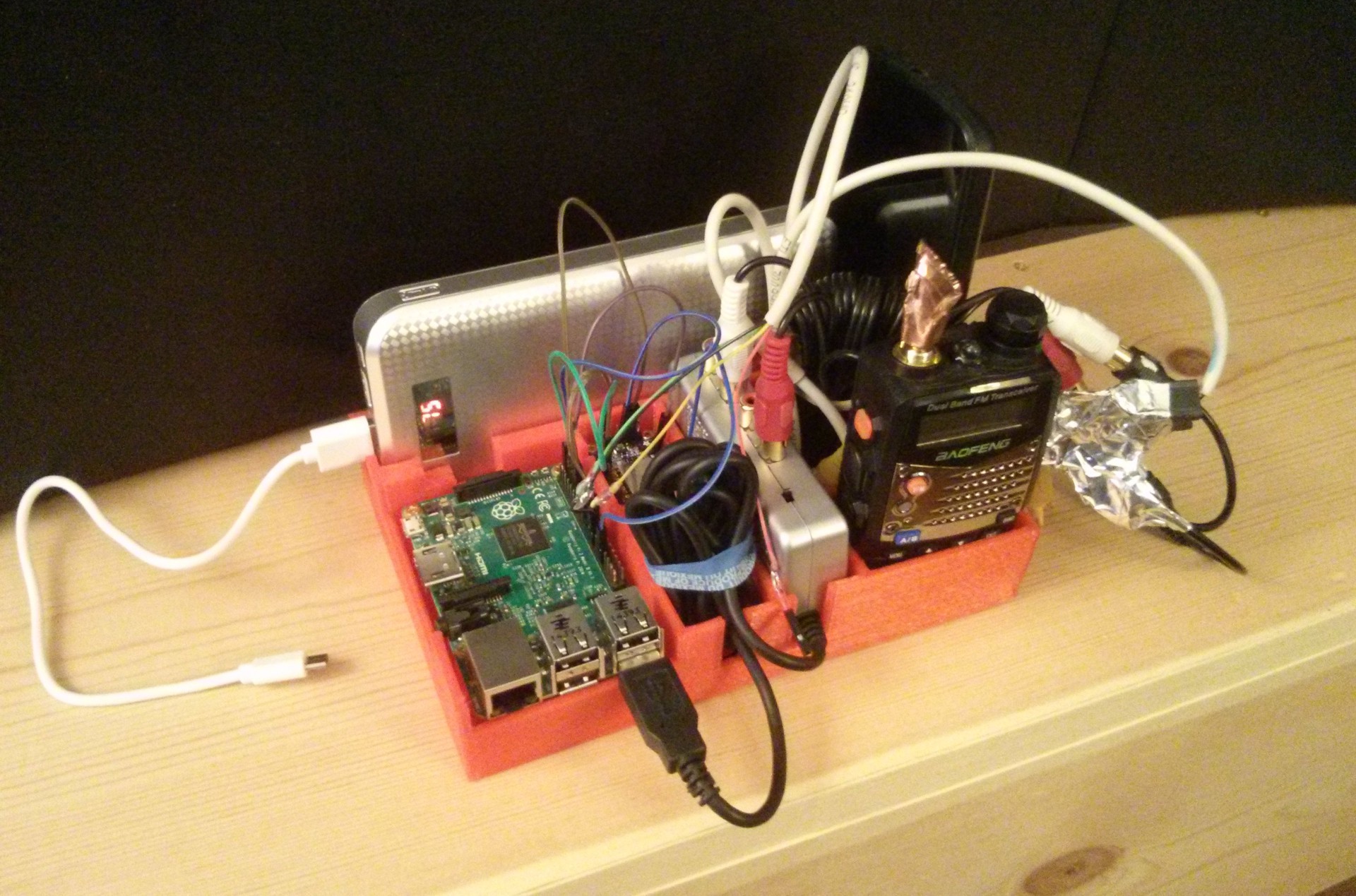
Built TRILLSAT-G (G for groundstation), a self-contained, mobile system for proof-of-concept testing of TRILLSAT-1 with no reliance on power grid, Internet, or cell infrastructure whatsoever during testing. I had to rework the software to create a groundstation mode, build another dummy load, add another ESP8266, USB powerbank, and designed and 3D printed a holder tray. My first version was built around the Pi 2 ARMv7, but I later moved it to a Pi B+ overclocked to 1 GHz, which matches the ARMv6 of TRILLSAT-1.
Replaced the 2016 Pi Zero W board on TRILLSAT-1 with a 2017 one which fixed GPIO 21 that I damaged years ago.
Replaced the MicroSD card in TRILLSAT-1 with a brand new one and rebuilt the OS and software again on the new card. It turned out that the primary reason I kept having corruption with my ext4 file system over the years, even after I re-installed it and ran fsck, was due to its peculiar failure mode, retention errors when the flash medium on this old, heavily used card apparently lost charge, the data corrupting only after I left it powered off for several weeks.
I realized that the 1.8 K ohm I2C pull-up resistors on the Pi Zero W were offline when the Pi was powered down, and neither the ESP, LIS3DH, nor ATtinys had their own I2C pullups. I tried to add my own pullups but the Pi GPIO passive protection diodes sink them directly to ground if the Pi is powered down, so I investigated tri-state transceiver chips to isolate the bidirectional signals, but then realized the Pi Zero in its reset state (where the reset, or "RUN", line is held down continuously but the power is still applied) allows the pullups to work and uses less power, a viable way of keeping the Pi board alive, yet in a coma to keep those I2C pullups enabled. This was very important so the EPS8266 could control the ATtinys if the Pi went down in an emergency situation.
Connected the ATtiny reset lines to the ESP8266 in case the Pi went down but had to add external pullups since the high impedance INPUT mode in NodeMCU on the ESP8266 drew just enough current to sink the weak pulldowns of the Pi Zero W on my ATtiny reset lines, which caused the inverted-logic transistor base to flip high under RFI conditions (such as during motor use when I often need to perform emergency shutdown), triggering a reset.
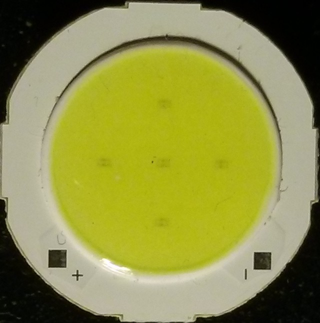
Found I was lacking proper pullups on my LED spotlight and added them. Then the final and 6th LED of my hexagonal, dollar-store flashlight board that I used for its spotlight burned out due to cascade failure due to their parallel arrangement. I bought a set of LED flashlights (about a dollar each) to replace it which contained a COB, or "Component On Board" where 5 surface-mount blue LEDs are mounted to a PCB and a layer of silicone containing a yellow phosphor converts them to white light.
I decided to add a silicon diode to drop the voltage slightly down from 5v, in conjunction with my current limiting resistor, to try to avoid potential thermal runaway in case I exceeded the power dissipation of the device on my first board.
Software Additions or Removals:
- Upgraded NodeMCU to a newer version 2.2.1-master_20190405. This fixed the KRACK vulnerability, allowed Android 6 and above to connect to SoftAP access point mode again, and allowed me to turn on the new LFS (Lua Flash Store) with 128K to save RAM. Also added the DS18B20 and I2C modules.
- Began using matplotlib, NumPy, and Scipy Python modules to improve my motor drive system (more on this below).
- Removed the Python Pexpect module, since I never really needed it.
- Converted all of the TrillSat Python 2 software to Python 3 since Python 2 was end-of-life and the Scipy module would no longer compile on my Linux distro. A lot of things broke that I had to convert:
- Switch my file() commands to open()
- Many of my literal strings were strings of bytes, so I had to specifically indicate such with b''
- The APIs of many libraries that I used only accepted byte strings or bytearrays, forcing me to convert from/to them using .decode('utf-8') and .encode('utf-8')
- There was a lone print "" that I had to convert to print("")
- I had to replace a lot of chr(x), remove some str conversions, or use 0x hex values directly (instead of encoded in strings as "\x") when they were not applicable
- An integer floor division issue with my XMPP status screen caused a large floating point value to take up the display
- Released SIMTHEO decoder version 1.2, correcting a delay bug, and modularized it so it compiles into dynamically-linked libraries for the Pi Zero ARMv6. I then had to generate two different SIMTHEO binaries for the ATtinys in their own subdirectories since my newer dynamic-linked libraries require different pre-processor defines due to the simplicity of my API.
- Successfully ported my AVR-GCC ATiny 1634 roguelike game engine for ARMv6 Pi Zero W as a finite state machine which works in combination with the dynamically-linked SIMTHEO decoder library. The game's "blind" short-text-string mode is ideal for allowing simultaneous, multi-user play over the port-based nature of packet radio with very little load on the Pi Zero W CPU. It would be trivial to change the theme from medieval to sci-fi, space, or ham-radio related.
- Removed my Virtual PTT system lieu of Dire Wolf's TXINH "inhibit input" option and added a jumper to allow this to work.
- Began working on version 1.2 of TrillSat's operating software which includes many of the changes below but has not been released yet. This includes a new, separate Python 3 module for the motor drive system.
TrillSat version 1.2 updates (not released yet):
Found and fixed 3 major bugs (compound, multivariable bugs):
- Fixed the AX.25 texting bug that prevented full, bidirectional XMPP-to-AX.25-to-AX.25-to-XMPP (smartphone-to-smartphone without any desktop computer involvement). Bug was due to 3 tricky, concurrency race conditions that were hard to isolate. Wrote script to automate simulated test environment.
- Fixed the BLDC gyro bug that was cutting out at high RPMs, more often if tilted to one side than the other. Bug was due to me nesting an interrupt function inside the wrong interrupt to bypass a hardware failure which caused gravity to affect the sensitivity of the X-axis acceleration detection differently depending on the direction of the spinning gyro and whether it was accelerating or decelerating, causing a feedback loop that triggered the accelerometer, which then interfered with the time-critical Hall-effect sensor interrupts monitoring the gyro.
- Fixed the I2C bug in my driver code which had been causing unreliable transfers for years. It turned out that I was sending an ACK back to the Pi without thinking the session was over, causing all kinds of overlapping interrupts. I also didn't perform a check to see if a Stop occurred during a read or a write, yet I was running my I2C commands as if it was a write, slowing time-critical processes. And the ATtinys were spontaneously resetting during motor use until pullups were added, confusing the problem.
Found workarounds to 3 notable bugs:
- Discovered that packet communications just three feet apart worked well in one direction but not the other, depending on which station was hosting the PBBS, exposing a timing issue. This turned out to be due to the infamous Delay between PTT assertion and audio packet - Causes dead air for seconds bug when using Dire Wolf 1.5 and my SYBA SD-CM-UAUD USB sound adapter (with the CM119 chip). Found a workaround by using ALSA's "default" plugin (in my case, "ADEVICE default:Device") instead of using the "plughw" plugin (in my case, "ADEVICE plughw:0,0"). TRILLSAT-1's SYBA SD-CM-UAUD USB sound adapter is called Device, a generic (and thus confusing) name.
- Ran into the Invalid Transmit Channel issue with kissattach where it tried to transmit on the wrong ports (8 and 2) at startup. I was able to use the "kissparms -c 1" workaround to set it into crc-type "none" right after kissattach. Apparently it's how the kernel implemented KISS.
- In my Baofeng UV-5RA radio in TRILLSAT-G, when the squelch is set to 0, the FM tuner will not activate when briefly pressing the Call button, but it works fine when squelch is set to a non-zero value--some kind of firmware bug, apparently.
Packet Radio system:
Tested live radio for the first time instead of in pseudoterminal simulations and realized that my use of multiple ports (while fine in testing) caused several issues in actual use on a single sound card, since different ports are designed for different TNCs, and there is really no reason I should use multiple TNCs unless I have multiple transceivers. So I passed my own "--mode" argument in the ax25d.conf sections at the end of the trillsat_bbs.py line to allow the software to launch in different modes depending on the callsign SSID value.
Had to create a rotating socket mechanism to increment up to 10 sockets in a ring buffer to ensure that one was always available since I could not programmatically shut down and restart the pigpiod daemon if the radio got stuck during programming in the middle of an AX.25 session since it couldn't wait for Linux to release socket 8888.
Turned off the low battery voice on both TRILLSAT-1 and TRILLSAT-G to keep it from interfering, something I first noticed when testing TRILLSAT-G over the air since it had a smaller battery.
Created an elaborate process which puts the AX.25 pipeline into a "stupor" (confusing senses, making it disagreeable, putting it into an alternate reality) to allow the single VFO, during the packet session, to temporarily switch over to the APRS frequency to send out a beacon. Since I could not break the complex chain of AX.25 communication that takes place, I made the thing sluggish and confused on purpose during the short time window when the radio changes frequencies and sends out the beacon, and then I woke it out of its stupor. I used kissparms and axctl to modify the persist, T1, T2, T3, and IDLE values, paused the PBBS, muted the mic, inhibited PTT, and programmatically told the radio to change frequencies with confirmation and failsafes in case it locked up or was on the wrong frequency.
Tested sending a text while a PBBS session was in progress on the same port from the same caller (same callsign and SSID), something that shouldn't be done since the caller would be needlessly tying up the server. This created conflicts with my implementation of the POSIX IPC message queues, which I create on the fly named after the user's callsign. So I put in checks to prohibit this connection and to limit the number of maximum users to keep the bandwidth and CPU usage on the Pi Zero to reasonable levels.
Published my first video of the radio system in operation, the first demonstration of the radio systems that anyone besides myself had ever seen. I showed all radio systems working, over-the-air packet radio communications between TRILLSAT-1 and TRILLSAT-G, including the in-session APRS beacon. Everything was on battery power with no Internet or cell towers, and I even removed the router completely. It was all at 1 watt, on 50-ohm dummy loads only a few inches apart, using the "A decoder" of Dire Wolf 1.5 as a software TNC. It was demonstrated on 145.030 MHz, and the APRS beacon was demonstrated on 144.390 MHz.
Main Motor Drive:
Decided that the motor drive system of TrillSat was too complex (too many modulations atop modulations) for me to use simple heuristics or to get the system to "drive over the hills" in the torque curve as I outlined in my earlier Three-Tridant Orbital Mechanics diagram. I needed precision much higher than my crude sensor data provided, since I was using feed-forward methods to try to predict the current needed to drive the motor when it is operating in open-loop zones in-between sensor readings, and the craft was heavy and wobbly. Decided that the dynamic forces would have to be mathematically modeled unless I added more sensors and systems (which I didn't want to do).
Began writing my first scholarly/academic paper in LaTeX on TrillSat's orbital dynamics, heavy on the equations, using algebra, geometry, trigonometry, inverse elliptic functions, equilibrium equations and vector decomposition. It was the most math that I had ever done since my college Calculus days. I wrote about 70 pages of algebra until I was able to extract TrillSat's equations of motion into about 30 core equations on two pages.
I had to teach myself the basics of astrodynamics/orbital mechanics, and lacking experience with the subject, I made a few decisions:
- Excluded momentum, since it was too complex for me to model, and I was hoping it would be negligible if I drove the motor (and planetary mass) slowly.
- Decided on Cartesian coordinates (even though I have both linear and rotational elements) and used parametric equations to bypass some of the computational problems. There are times I really need Polar, but it wasn't often enough to offset the benefits of Cartesian.
- Used "relative" spatial relations to simplify the math, so I have to perform a series of calculations to find absolute values.
Decided to apply a computer graphing library, the matplotlib Python module and NumPy, to give me some visualizations, since TrillSat's clockwork rotations and changing angles means that many of my equations are strings of cosines, sines, tangents, arctangents, and I had a hard time visualizing whether my calculations were correct and not "out of phase".
I couldn't find a mathematical solution to find the inverse of the incomplete elliptic integrals so I applied the optimization functions of the Python SciPy Library to approximate it. In my case, it did it surprisingly quickly with high precision, but I needed about 1,000,000 complex calculations used in real-time on tiny microcontrollers, so I had to pre-generate them.
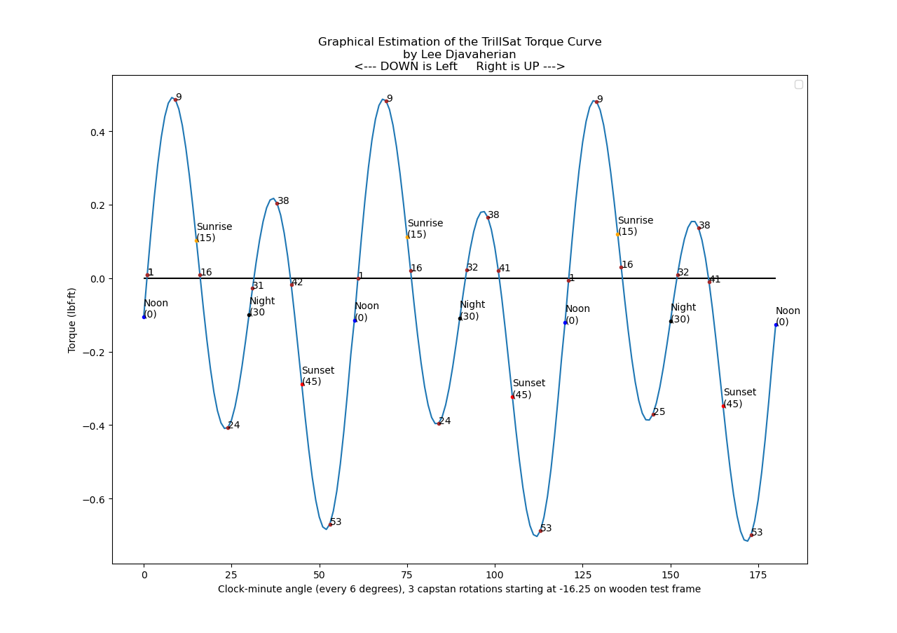
Using the new math of the torque curve (shown above), I performed my first locomotion tests on the tether at various PWM values and run times for a single 360-degree orbit, without any sensor feedback, but they were very erratic and chaotic, with the mass stalling, then whipping around causing the whole thing to swing.
Also during those tests, I accidentally touched the wrong wire feeding the batteries back into the charger which caused the ATtiny 1634 motor driver Sawyer to lock up and initiate the motor drive algorithm with long time parameters, ramping in speed very slowly while on the tether. I had to quickly untie and yank out the capstan to prevent motor damage and quickly unscrew the cover panel and short the reset line to the grounded panel. So I finally enabled emergency use functions over I2C on the ESP8266 in case the Pi locks up or goes down during motor tests, so it can shut down the motor controller ATtiny, Sawyer, when needed.
I decided that the motor modulation system, even with the torque values, was exceedingly more difficult than I anticipated and decided to focus more effort around it as the "Delta-v Motor Drive System", to maximize the precision of all elements involved so that the motor stayed inline with the idealized mathematics as much as possible to ensure accuracy. It's like a spacecraft in a Keplerian orbit--if you can provide the correct Delta-v thruster burn (an orbital maneuver) to get it into a certain orbit, physical law will take care of the rest, but tiny errors in the maneuver are grossly exaggerated, so it will be way off course until you reach a point where you can apply a correction.
The system and math are too complex to run in real-time on the ATtinys and require the full power of the Raspberry Pi's ARM processor with floating point math. Even this is too much for the ARM processor in real-time using Python 3, so I had to stage a pre-generation and then stream the torque values in real-time to the ATtiny. But the two Hall-effect switch tolerance zones were absurdly large, way too large to both correct for error or trigger data block loads of torque values, what I call "chunks", reciprocating memory buffers in the ATtiny.
What totally amazed me was that this tolerance (about 50-55 degree error for each sensor position, 15% of the total orbit, 45% for all three "sectors") is so large that the orbit can be divided into 6 sectors, "Six Sextant Orbital Mechanics", with 3 of the sectors being inside the tolerance zone themselves when the magnetic field is detected, and the edges of those 6 sectors are very precise. I was then able to create a phase lock system to auto correct the motor torques at those 6 edges, with I2C hardware flow control that triggers a chunk reload of the pre-generated streaming torque data every 180 degrees at the day/night boundaries.
In between these phase lock sensors, however, the craft is traveling by pure dead-reckoning, so I maximized the precision in my code to minimize cumulative error:
- Changed my 8-bit timer resolution to 10 bit, increase my timing resolution from .1 second resolution to .0005 seconds (.5 ms)
- The electrical current had to be moved from 7 or 8-bit to up to 10-bit (1024) phase and frequency correct values
- Any _delay statements were removed to allow modulation at small angles and higher speeds
- Passed a lot of 16-bit values over 8-bit serialized I2C, and had to brute force my own "signed-bit" since I was having trouble with the 11th bit negative values of my 10-bit torque values (the two's complement/endian arrangement gave me some trouble and I was getting fatigued)
- Scaled the floating point values properly into integers to keep the precision rather than truncate it
- Increased the shaft resolution of my math to 3600 arc to match the .1 degree resolution of the accelerometer
- Moved my timer-interrupt-based, Hall-effect sensing directly into my motor drive function to save some clock cycles
- Ensured the system switches between Sign-Magnitude (10-bit) and Locked-Antiphase (9-bit) modes automatically during the rotation
- Used the ESP8266 ADC high-impedance voltage-divider circuit (a redundancy item I added) to read series motor voltage (which affects speed and torque calculations) and also indirectly allows me to deduce the Batt 2 bank voltage after its ATtiny ADC pin failed
Created new testing methods for my motor drive system inverted on a table since the dynamic torques do not exist and the motor behaves completely differently. Had to "serialize" my angles in almost the same way Linux seconds serialize the rotational hands of a clock face for my torque streaming method that converts between motor shaft angle and positions within two, reciprocating, linear memory chunks. I ended up using integer division and modulo operations frequently and found that a good way of doing this was to rely on a starting offset that was less than a chunk in length (less than 1/2 a rotation) combined with the total number of motor torque values sent.
I could not apply effective hysteresis for the noise at the edges of the Hall-effect switches due to the peculiar interlacing of direct and indirect sensing and had to incorporate complex time and distance-based debouncing (not true mechanical switch debouncing but I treat it as such), creating speed-sensitive timing delays to change the debouncing thresholds and take into consideration the width of the 6 sextants, which conveniently differ by a 1:2:6 arclength ratio.
Created a clock-minutes and clock-seconds angular scale. The 3600-arc resolution of my motor drive system acts like seconds if they are applied to a clock and not degrees or arcseconds on a compass, which is why I prefix my angle terms with the word "clock", like "clock-minute" to differentiate from arcminute. The clock-minute angles are simply angles at every 6 degrees, like minutes on a clock face.
Created a finite and impulse burn system using that scale. Just like in a real spacecraft, there are two types of burns, or orbital maneuvers in TrillSat, a long-term "finite burn", which I call a clock-minute burn, and a short-term instantaneous or "impulse burn", which I call a clock-second burn. And the analogy holds surprisingly well, for my long-term, clock-minute burns are designed to traverse any distance, from point to point without stopping, requiring more calculations and techniques to keep it on track, whereas my clock-second burn is very simple and short, almost instantaneous, designed only for moves within 6 degrees, with no ramp, torque streaming, nor Hall-effect correction enabled.
Added an auto-calibration routine to automatically find the angles and offsets of the initial sensor placement and motor conditions for accuracy. It automatically drives the motor and reads the sensors in various ways to deduce the following:
- angles of the 6 sextant zone edges
- mechanical gear slack
- magnet holder assembly error
- static friction offset
It stores them in EEPROM with flash default fallbacks to prevent needless re-calibrations during programming and erasure.
Added some motor correction heuristics to keep the motor on track with the equations:
- sensor correction - correct known position when sensor finds it is wrong
- sensor catchup - if motor is too slow, hold last speed until it reaches new sensor checkpoint
- sensor reload - if motor reaches day/night sensor checkpoints, tell Pi okay to send next chunk
- motor boost - if sensor catchup is on, don't just hold last speed, increase speed in stages
- speed correction - if too slow or too fast, alter speed by 1/2 the error during next phase
I had to rework my ramp system to work atop the Delta-v system, instead of beneath it, to ensure time-and-distance critical maneuvers were not impacted. I was able to take advantage of the neat fact that a triangle that is twice the width of a rectangle of the same height has the same area (the electrical current and time that is used to move the motor). So I could replace that tiny "burn" with a more granular burn-of-burns, ramping up to the original value, but it would take twice as long to apply, skewing the elapsed time. This is not a problem, since I'm concerned more with distance than the arrival time. Ramp downs, however, had to be excluded 10% of the time, since it interferes with real-time correction at the 6 sensor angles (zone edges).
Created an auto-motor-move system to ease programming since the motor shaft in certain positions blocks one of the ATtiny in-circuit programming lines.
The Gyro:
After the gyro bug was fixed, I tested the BLDC gyro at 1800 RPM, 5 times faster than my original video. This puts about 2 lbf of force around the wheel, and it worked without breaking apart under its full mass. I haven't tested it on the tether at this speed yet. There is less than 1 mm clearance in some places and thermal expansion could cause the wheel to eventually scrape, but it should hopefully be enough for me to show proof of concept of a stabilizing effect in the future.
Planned updates:
Decided to 3D print and add, what I call a "camstan" in the future, but it's a larger change that I won't revisit until later since it is highly eccentric, too wide to fit into my pulley frame, and both parts will need to be redesigned, not just one. Also, the mathematics of adjusting to the error points crosses Cartesian/Polar systems, complicating the math. In the meantime, I will rely on my newer Delta-v Motor Drive System to compensate, as best as it can.
The camstan design came about after I graphed the torque curve and noticed that my 2018 truck analogy was acting like a fixed-gear system and lacked a transmission, so I combined a cam with a capstan to mimic a continuously-variable automatic transmission, or CVT. A capstan can be shaped like a cam since the tether acts somewhat like a cam follower. It turns out that since there are only two sinusoidal cycles per rotation, a simple, dual-lobed, camstan could work, but there is some cleavage error where the tether spans across and cannot act on its surface (example below, the cleavage dramatically smoothed out without any tapering):

I designed a model of the camstan by having my Python 3 torque-generation function output a series of torque displacements (radii) for each of the 3600 angles per one rotation, and using the Cartesian-to-polar relationship was then able to convert them to [r cos theta, r sin theta] x,y pairs which could then be read by OpenSCAD's Cartesian-only polygon function to generate the unique off-axis, dual-lobe shape, which I then extruded into 3 dimensions.
But rendering the actual shape for 3D printing, with the tapering (not shown above) was difficult, and I had to stack a series of slices of the entire polygon at various exterior offsets (kind of like scaling them) to match the algebraic, Cartesian function of a half-circle, like cutting a shape into the fore-edge of a book.
Decided to add a new sensor and plan to 3D print a minor change in the future to allow it to be incorporated. I was almost correct in my assumption that I had the bare minimum sensors needed for accurate motion, but I needed one more, which I'll explain in the paper I'm writing on TrillSat's orbital mechanics.
Decided that when I build the LoRa space pod, I will add a keyboard and display to create a secondary LoRa client for craft control (since I will need another LoRa board to communicate with it anyway).
Explored creating a virtual astronaut simulation inside the CPU on the space pod which I call an AAR virtual pet (an Alternate, Augmented Reality) since it interacts with its own alternate reality in combination with real world sensors, but without visual data (sensor data only). The astronaut could have some autonomy, "leave" the pod and enter the main craft affecting some of its functions (as if an astronaut was walking around flipping switches and performing manual overrides) and distant callers could get status updates on what the astronaut is doing.
Explored creating the 2-meter antenna as a pendulum attached to the top of the craft to act as tuned mass damper, raise its height, raise the center of gravity of the craft, keep vertical polarization, and act as crude X-axis accelerometer for additional redundancy. Curiously, the length of the antenna is fixed to match a certain RF frequency, and it would serve dual-purpose, also match a physical pendulum frequency.
Discussions
Become a Hackaday.io Member
Create an account to leave a comment. Already have an account? Log In.