 Alex
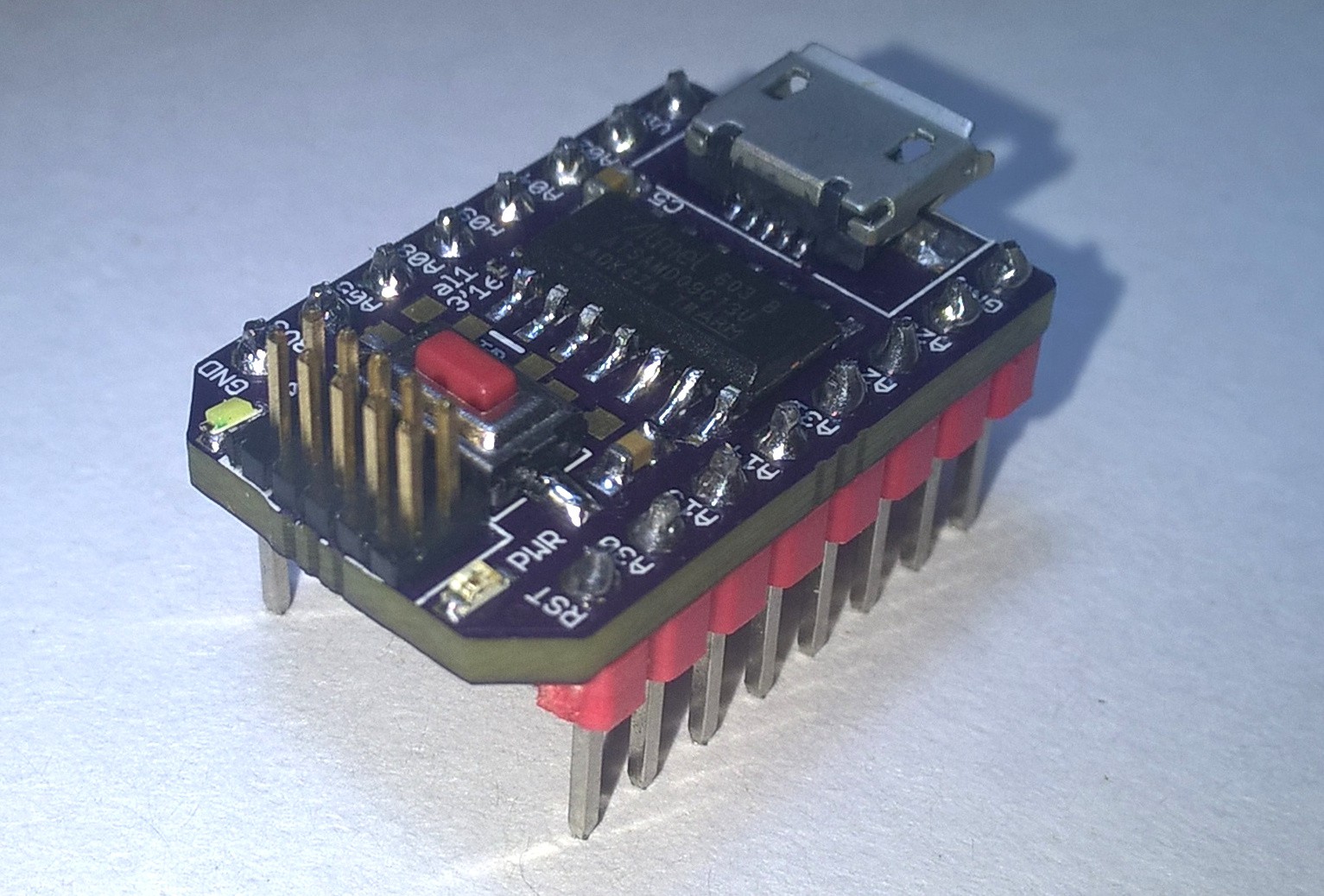
Alexbuild this board to getting started with the SAMD microcontroller family after I made the mistake to try the much bigger SAMD21 first. The SAMD09 used here is he smallest from this family and therefore has the shortest (still 709 p.) datasheet. I think this board will be, as my other microcontroller breakout boards, very useful for an early prototyping phase on breadboard. So far I quite like the SAMD09. If you compare it to the the ATmegas there are a lot more possibilities. Maybe this is the Arduino Nano killer for me.
Features
- 3.3V 0.8A LDO (1117-3.3)
- powered from USB, Vin pin (3.6-13.8V) or regulated 3.3V
- on board USB to serial bride IC (CH340)
- reset switch
- SWD programming header
- optional 32kHz crystal (if not needed pins can be used as additional IOs)
- on board user LED (connected to PA02)
- on board power LED (connected to 3.3 rail)
Schematic

Partlist:
Part   Value        Package     Comment

A08                 0603        User LED connected to PA08
C1     100n         C0603
C2     15p          C0603       optional
C3     15p          C0603       optional
C4     10n          C0603
C5     100n         C0603
C7     100n         C0603
D1     MBR0520LT    SOD123      power selection diode
D2     MBR0520LT    SOD123      power selection diode
IC1    CH340G       SOIC16      USB-UART bridge
IC2    1117-3.3     SOT223      LDO
JP1                 1X08_OCTA   pin header
JP2                 1X08_OCTA   pin header
JP5                 2X05_1,27B  programming pin header
K1     mini USB     generic     Mini USB connector
PWR                 0603 	Power LED
Q1     3215         3215        optional external 32kHz crystal
Q2     CSTCRCSTCE   CSTCESMALL  12 MHz resonator for CH340G
R1     solder / 0   R0201       PA08 - pin header
R2     solder / 0   R0201       PA09 - pin header
R3     120  / 220   R0603       resistor for power LED
R4     120  / 220   R0603       resistor for user LED
R5     ~10k         R0603       pullup for reset
S2                  SMDSWITCH   Chinese SMD switch
U$1    SAMD09SOIC14 SO14        ARM Cortex M0+ microcontroller
PCB
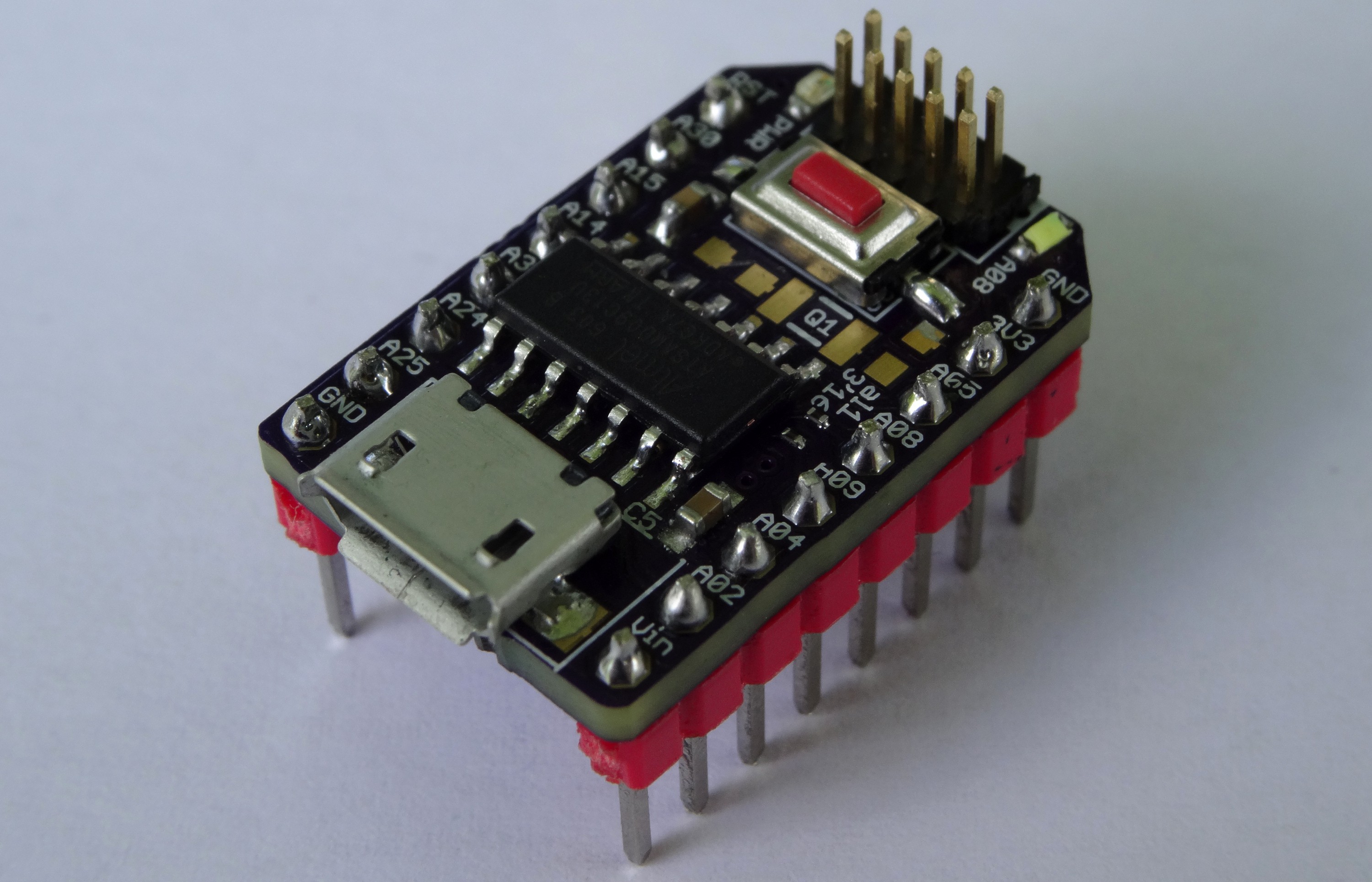
The PCB design is quite compact and does fit on an normal breadboard:

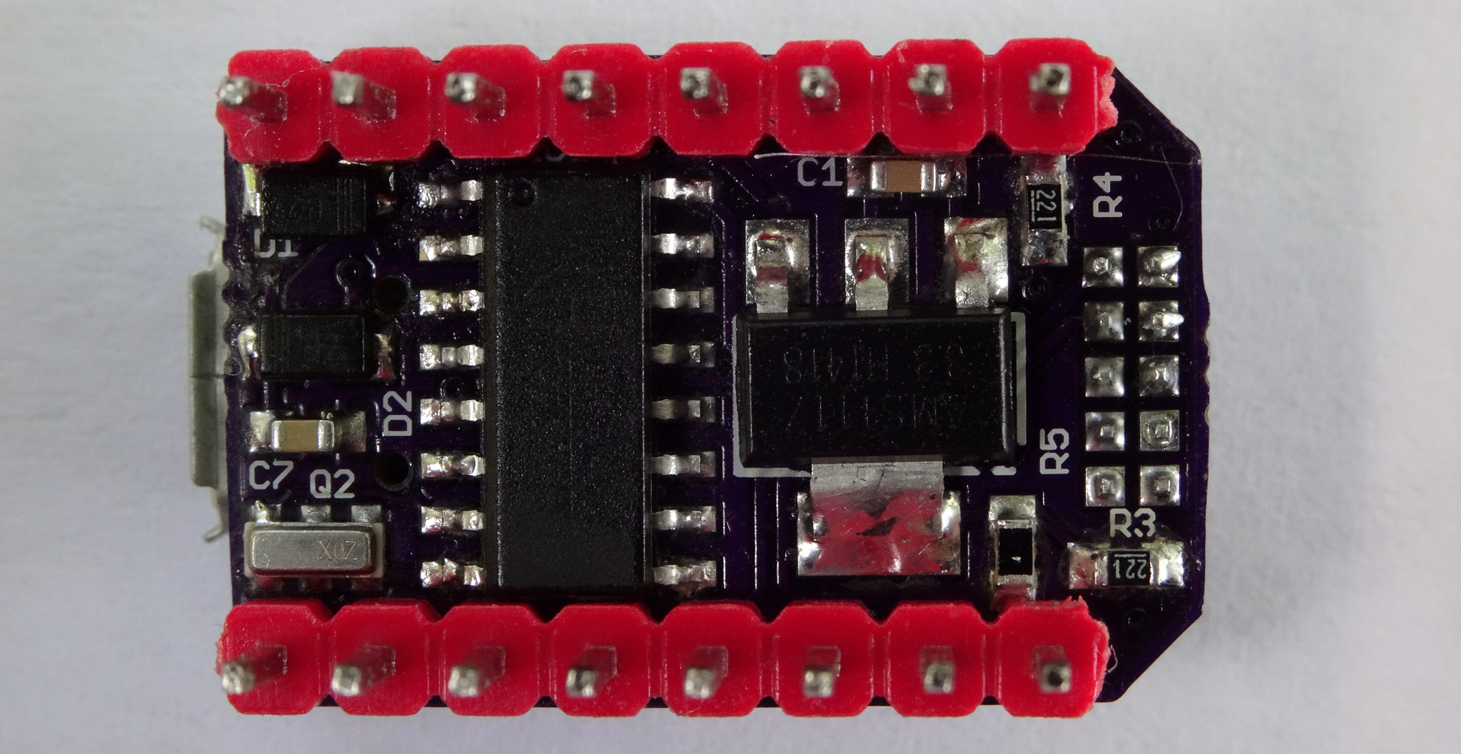
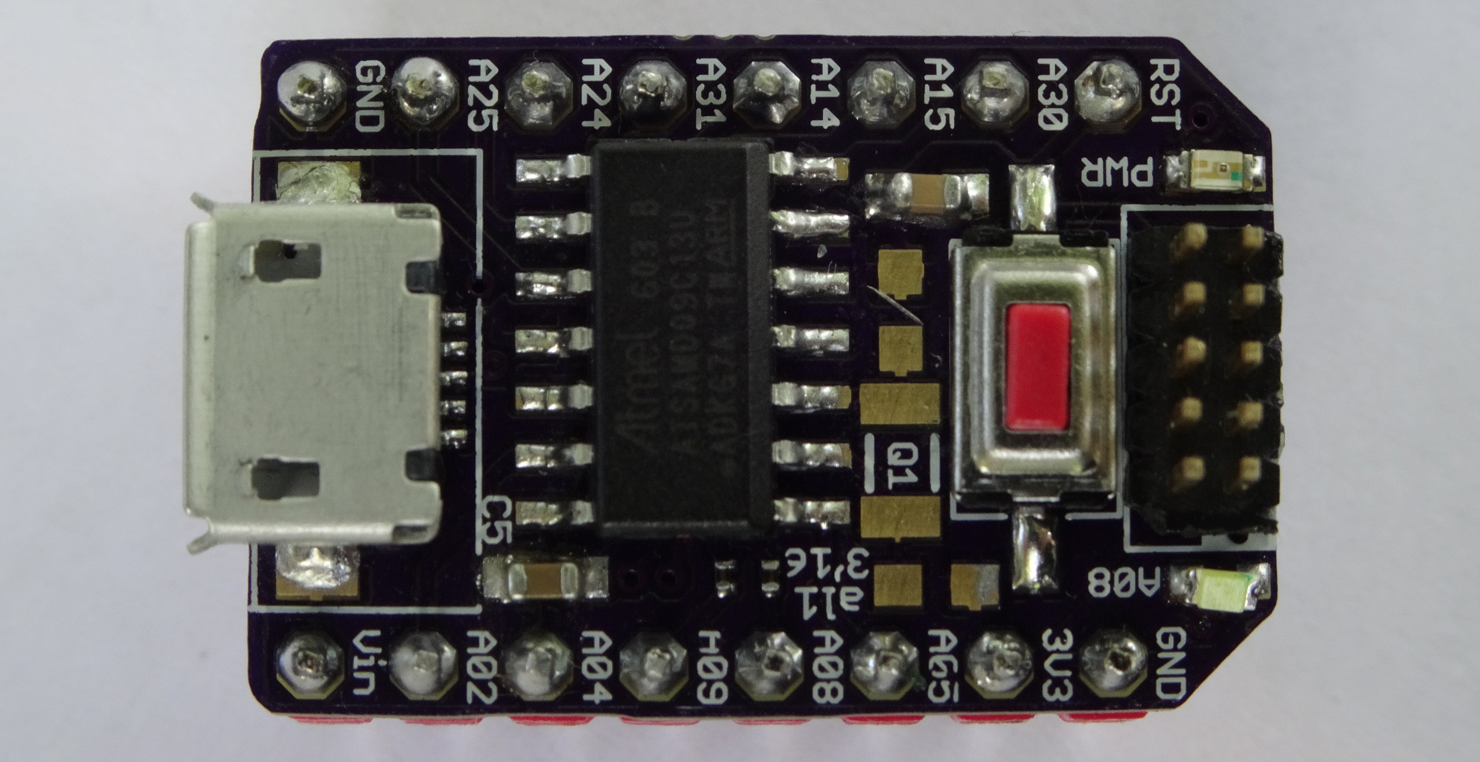
On the Top side (left image) are all components which must be accessible like USB connector, programming header reset switch and LEDs. To archive this compact format with some tricks were used like vias on pads (this is no good design practice) and the two connections of the LDO for Vout are use as trace. So this will not work without the LDO if powered externally with 3.3V
Thinking on / ideas for the future / notes
- A Hint when working with the Event System (EVSYS):
- In the Channel Register (CHANNEL) the bits [2:0] are the channel nuber like normal (0b000->channel0 0b001->channel1)
- BUT in the User Multiplexer Register (USER) the bits [11:8], which are also for the channel selection are channel#+1.( A zero means no Output in this case). So 0b0001->channel0, 0b0010->cannel1 and so on.
- This took some time for me to notice that, although is it also written in the datasheet (p.409 Table 23-5).
- This board should also work with the SAMD10C14 which has more features (like a DAC) and twice the amount of flash (8k->16k)
Errata
Rev 1.0 (date on the boards 3'16)
- The led label is wrong. It should be A02 instead of A08
Rev 1.1
....
Similar projects
This project is inspired and/or based on some of them:
 The connections are quite simple: Power, GND and for wires for the SPI bus (MOSI, MISO, CLK and !SS). The logic analyser on the right is also connected to the SPI bus for debugging. I will upload the early stages of the used code to github also.
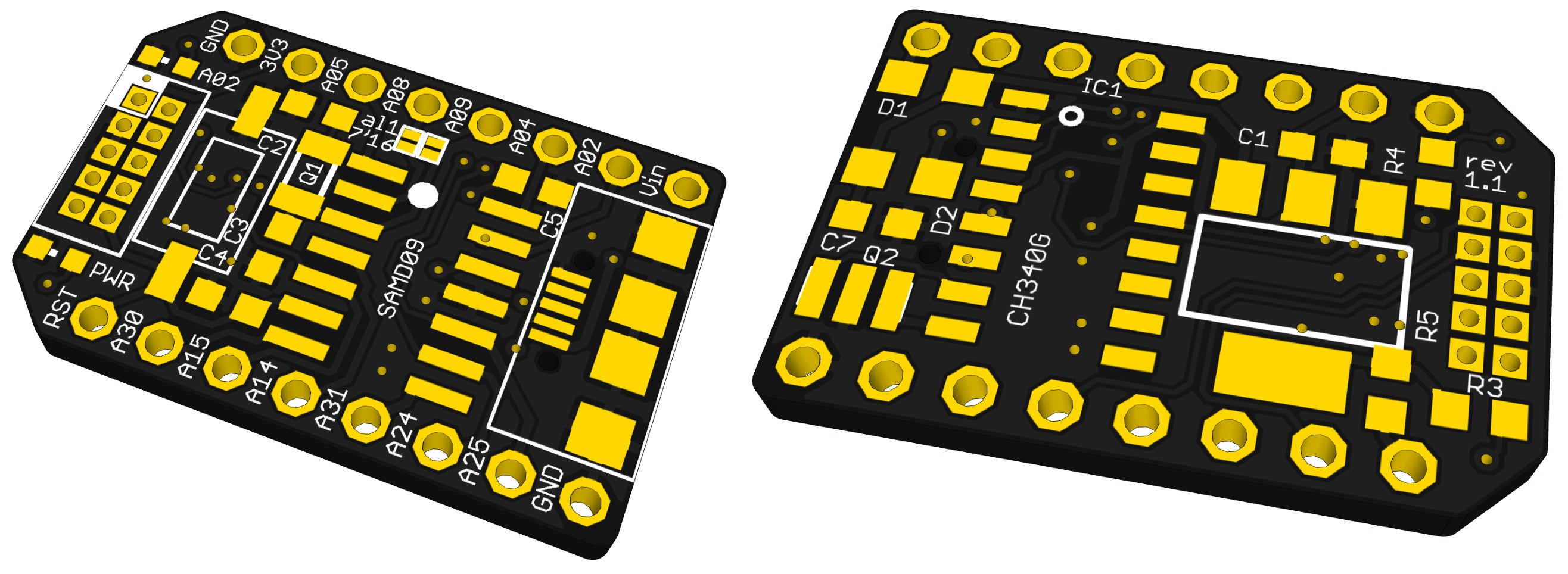


 Dave Vandenbout
 Ken Yap
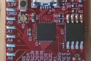
 greg
greg
thank you for the mention! I just finished the serial bootloader for samd09 boards. Still need to do some code Cleanup and create a Readme, but if you want to check it out its on my github linked in the project.
Have a great fourth.