Close
0%
0%

FlightCPU

An embedded data recorder for High Altitude Balloons.

Similar projects worth following

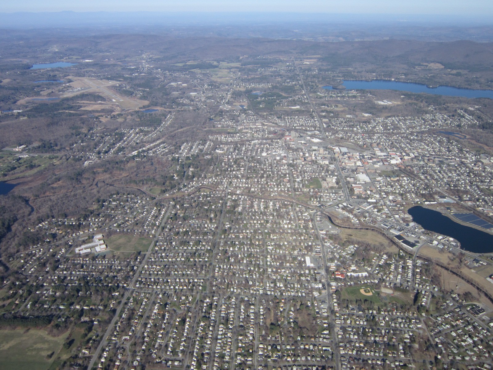
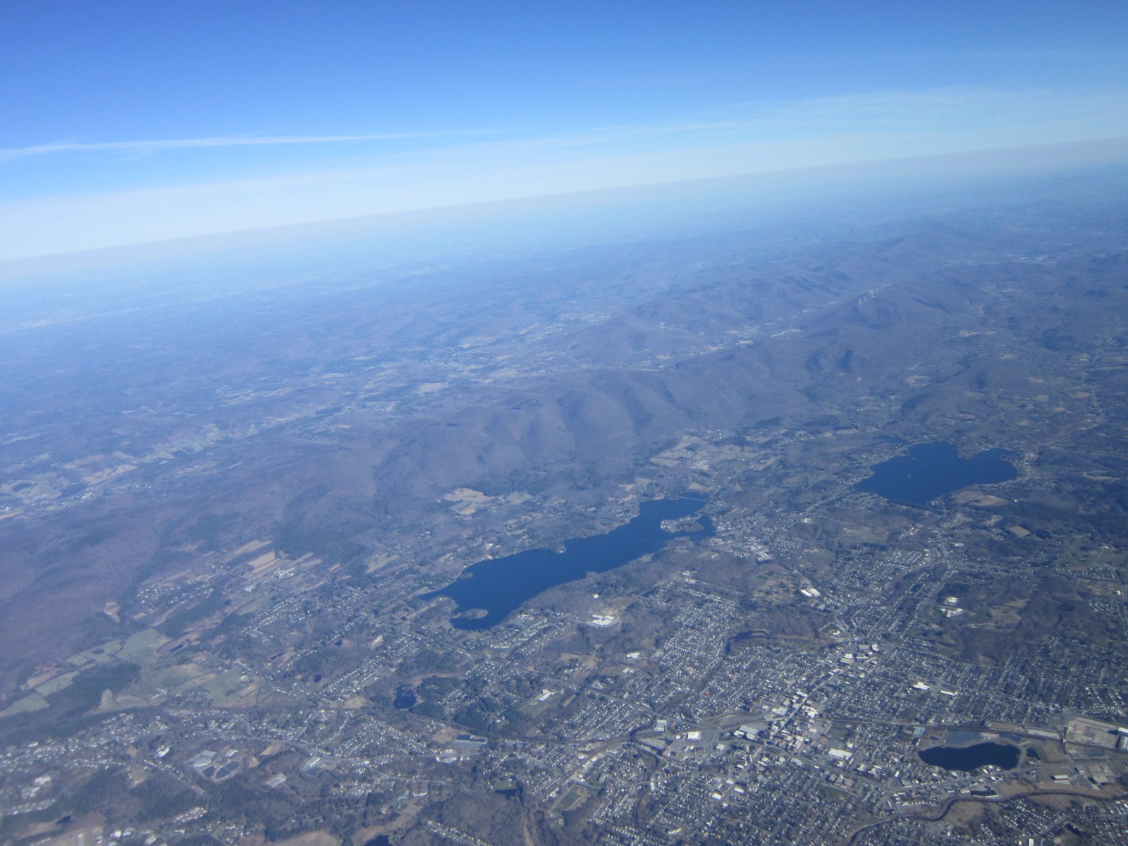
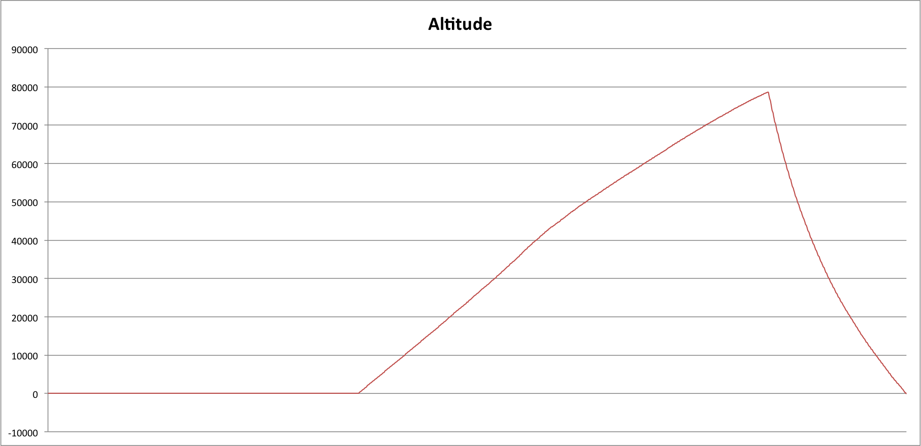
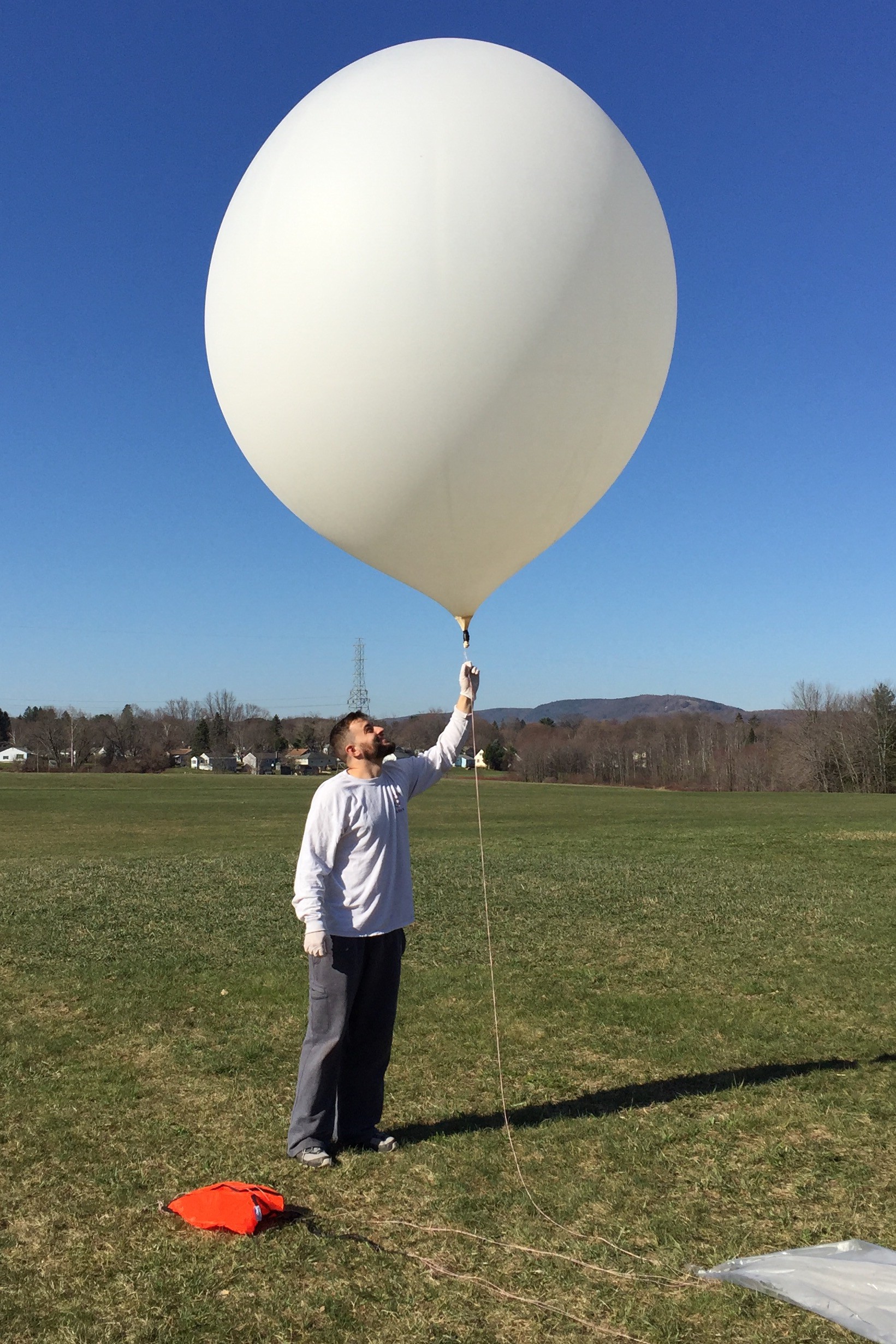
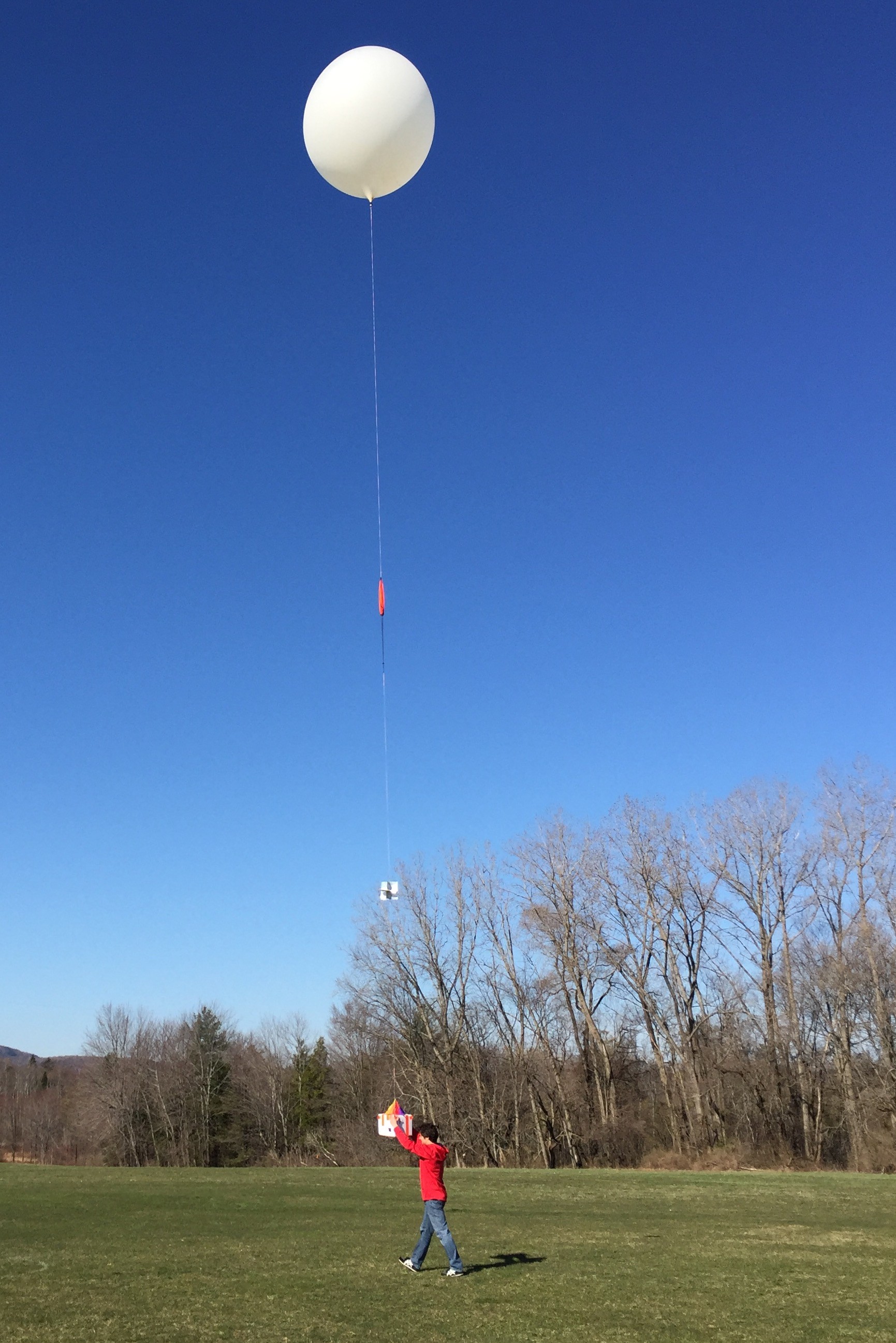
On April 17, 2016 my brother and I launched a high altitude weather balloon over western Massachusetts. The payload contained 3 cameras, multiple GPS trackers, and 2 data recorders. Everything except the data recorders were bought off the shelf.

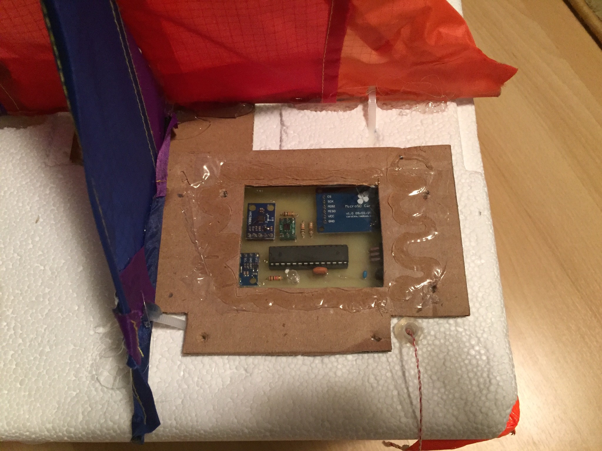
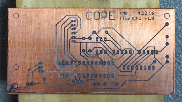
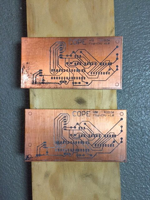
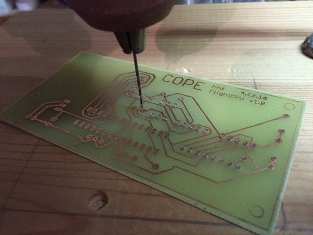
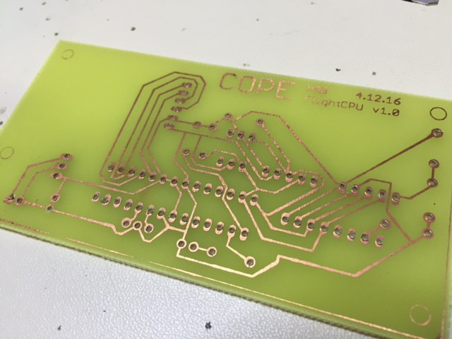
This project documents the build of the FlightCPU used to log data throughout the flight. If you are curious about the entire balloon launch process, we recommend you read through our project summary, uploaded in the document section. This 25 page detailed write-up covers all necessary steps in launching a High Altitude Balloon, from securing the correct components, to best practices in designing your payload and securing the flight train.

Also, be sure to check out the open source files on GitHub!

https://github.com/jcope/FlightCPU


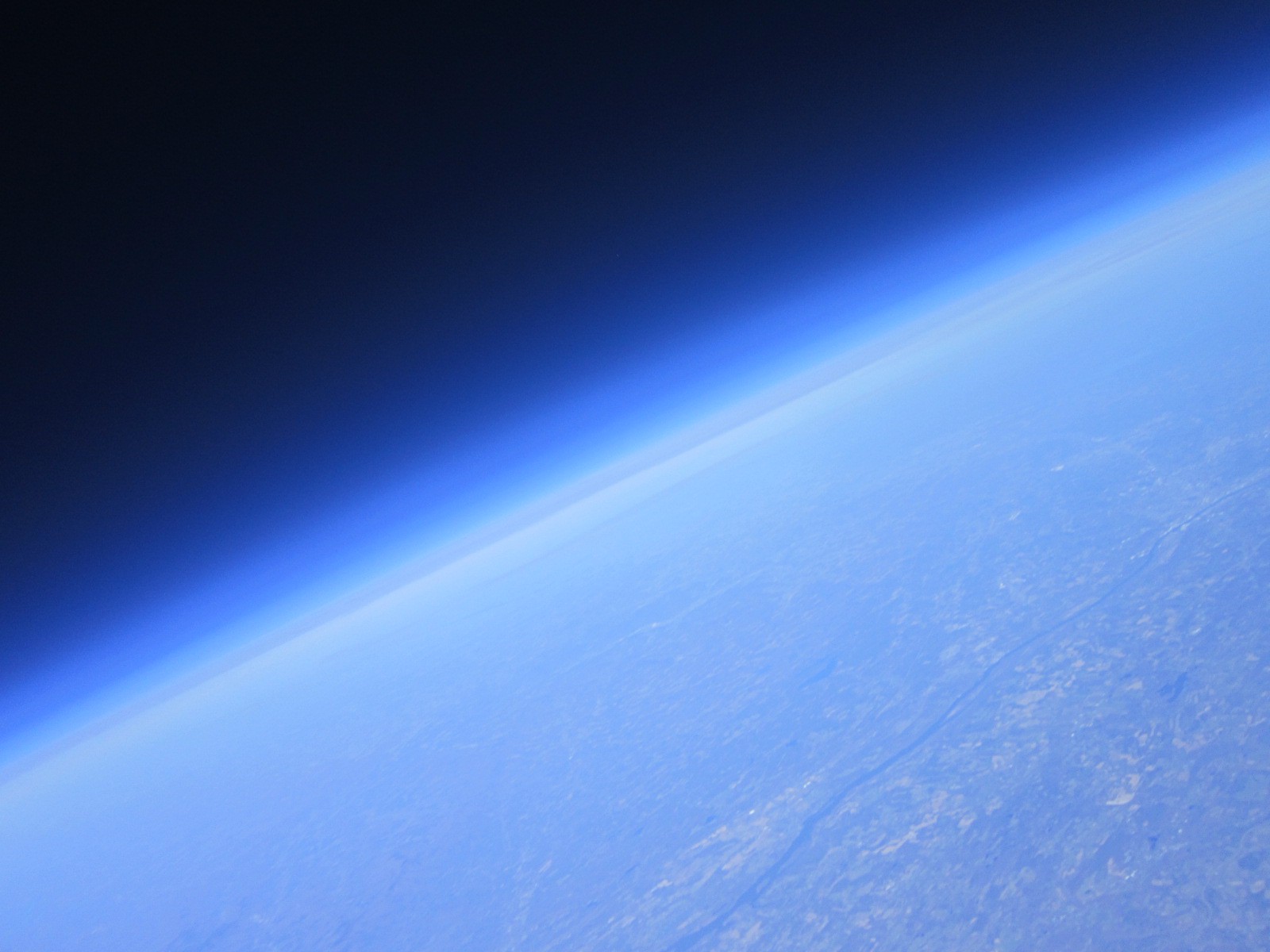
Launching a Hight Altitude Balloon (HAB) is a challenge in of itself. But what good is going to the stratosphere if you can't collect data during the flight? There are plenty of off-the-self data loggers we could have bought to perform the similar tasks, but in order to truly customize our data collection, I needed to build something from scratch.

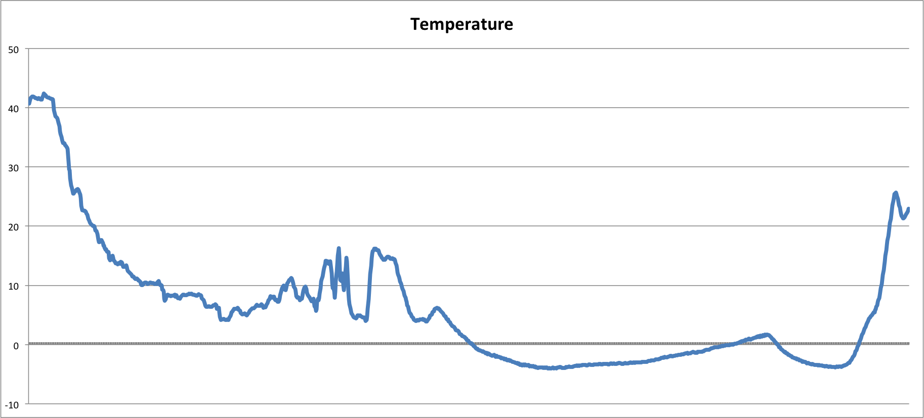
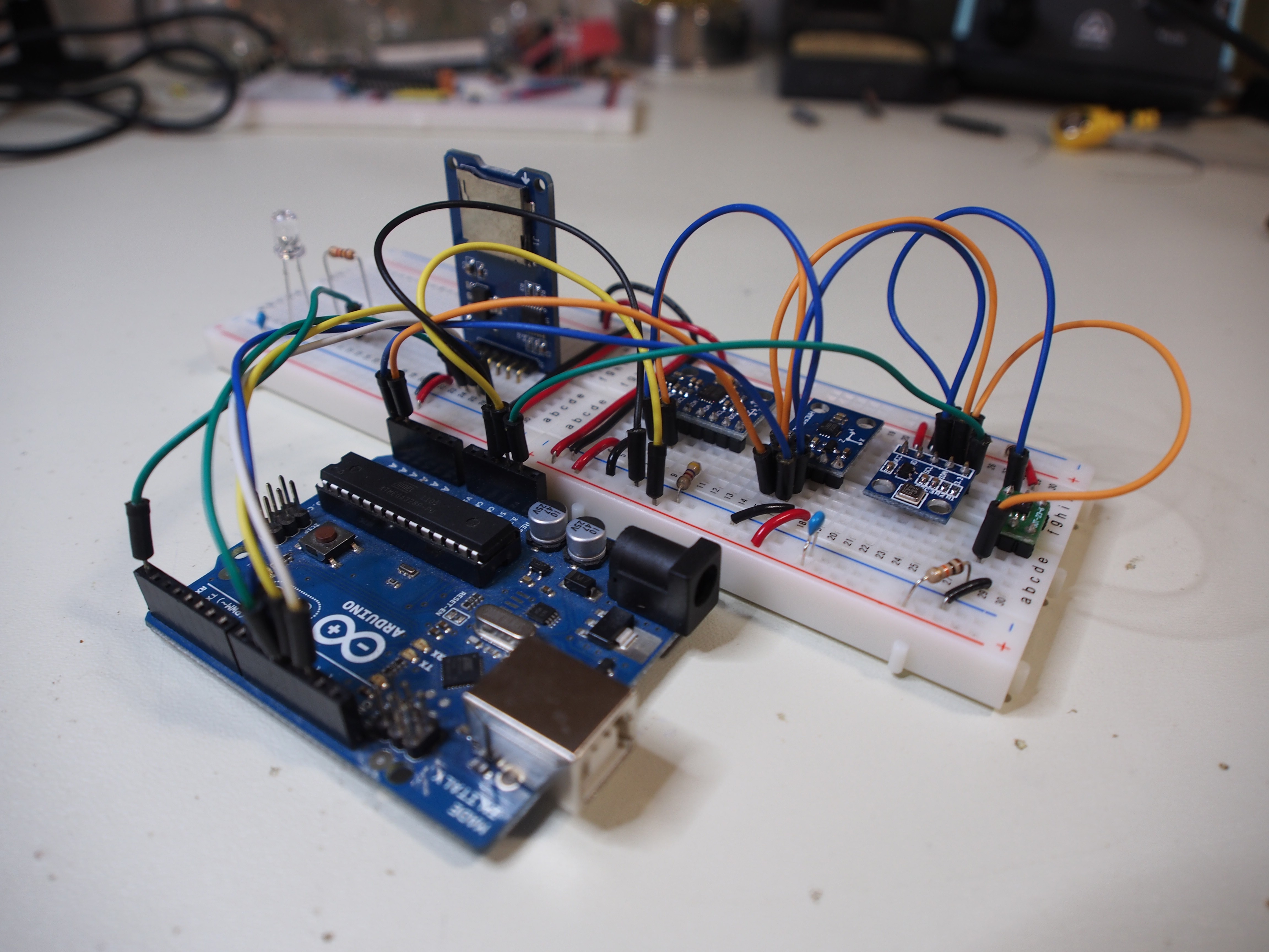
The FlightCPU is uniquely designed in that every sensor was chosen and the software was completely customizable. Because of the customization, we were able to provide separate resolutions for every sensor- a temperature sensor only needs to be updated 1/second while the gyroscope should be read multiple times per second.

The FlightCPU design should enable others to customize their own HAB experience, and take part in the joy of launch and chase!

Cope Brothers WBC.pdf

A detailed report on the entire High Altitude Balloon process. A must read for anyone interested in launching their own!

Adobe Portable Document Format - 2.61 MB - 01/04/2019 at 18:58

Preview
Download

FlightCPU_PCB.pdf

Eagle PCB Layout

Adobe Portable Document Format - 33.70 kB - 06/23/2016 at 13:11

Preview
Download

FlightCPU.pdf

Eagle Schematic

Adobe Portable Document Format - 62.00 kB - 06/21/2016 at 19:25

Preview
Download

  • 1 × ATMEGAA328P Arduino Microcontroller
  • 1 × SI7020 Humidity/Temperature Sensor (SPI)
  • 1 × GY-68 Barometer
  • 1 × GY-521 Accelerometer/Gyroscope
  • 1 × GY-271 Magnetometer

View all 11 components

  • Captured Photos

    Jeremy07/11/2016 at 13:34 0 comments

    No captions are necessary, just enjoy the view!

  • The Data Entry

    Jeremy07/11/2016 at 02:19 0 comments

    The FlightCPU provided very interesting data throughout the flight. Unfortunately due to calibration issues, the barometer did not give us accurate results in terms of absolute altitude, but we can infer the overall flight path using relative values. Other data points from gyroscope and magnetometer were difficult to parse, and even harder to graph. We are still working on the best way to visualize this data, so any suggestions would be appreciated!

    As you can see above, the temperature seems to fluctuate as the balloon rises through the atmosphere. Why is this so? Our best guess is cloud coverage (although the cameras didn't seem to indicate many clouds). It is also curious to see the temperature rise as reaches the top of the assent. Perhaps the sun had something to do with it? Note on the descent, you can see a slight change in the rate of temperature increase, we believe this lines up with the fluctuations we saw during the rise (keeping in mind the descent was much faster than the rise). One final note, the temperature starts to decrease right at the end of the graph. Because we found the payload in the woods in the shade, we believe this decrease at the end signifies the payload at rest, waiting to be found.

    The altitude graph is about as straightforward as it gets. Unfortunately, due to calibration issues, the absolute values are invalid, but the relative height can still be analyzed. Of interest, the rate of accent looks to be pretty constant, with only one slight change about half-way up. On the descent, the rate is decreases, signifying the work of the parachute and the thickening of the atmosphere.

  • Lift Off!

    Jeremy07/11/2016 at 01:40 0 comments

    We decided to carve out space in the lid of the payload box to secure the FlightCPU. This allowed it to be exposed to the elements, but in a way that did not damage the board. If we had placed the FlightCPU in the actual payload, we risked contaminating the data as we had included warmers to keep the cameras above freezing temperature. So placing the FlightCPU outside the payload was a must.

    Here you can get a good sense for the size of the ballon and the care taken to inflate it. Notice the latex gloves being warn- even the slightest oil form your hand can cause the balloon to prematurely pop.

    This picture shows the complete ballon, parachute, radar deflector (or is it reflector?), and payload. The entire flight line was about 40 ft. It was impressive to hold, as I could certainly feel the lift of the ballon on the payload.

  • Creating the PCB

    Jeremy07/07/2016 at 21:31 0 comments

    Full Disclosure: I have to give credit where credit is due. Everything I learned about home etching was from this HackADay article. I fully recommend you read it, and tailor the etching methods to your equipment and materials.

    http://hackaday.com/2008/07/28/how-to-etch-a-single-sided-pcb/


    PCB Etching is an art. You need the correct paper, apply right amount of pressure, create an acid bath, and have tons of patience. It took me around a dozen attempts in order to perfect the process for my environment, so by the time it came to create the FlightCPU, it only took 3 boars (1 wasted). Below is a visual walkthrough to help identify the steps it takes to home etch a PCB.

    In true Contact fashion.. why build one when you can build two for twice the price.

    The acid bath etches away the copper on the board, leaving only the traces applied during the ink transfer process. Here you can see the acid doing its part, eroding from the edges to the middle. I find it is best to wipe the board with a brush as it etches to help evenly distribute the acid bath.

    Here you can see the final product before we head over the the drill press and create holes for all the components. I used paint thiner to clean off the ink from the traces, exposing the copper lines that will be the electrical traces for the components. Not a bad job!

    A drill press is a must if you are serious about creating your own PCBs at home. There is no other way to ensure straight perpendicular holes when drilling into PCB. Also, the copper helps guide the drill bit into the correct place, so once you get into a groove, everything just comes together.

    And finally, the finished product. Well, the PCB at least. We still have to assemble the components and solder every junction, but that might have to wait for another log update.

  • Rapid Prototyping

    Jeremy06/29/2016 at 16:08 0 comments

    Any good hardware design needs a solid development environment to help debug and isolate issues as they arise. The final FlighCPU will be etched on a PCB, but until then, I needed to rely on breadboard and the Arduino Uno.

    All sensors where purchased off of eBay for relatively inexpensive prices. If you can absorb the slow shipping speeds, this is definitely the way to go. The Humidity/Temperature sensor was a left over from an IOT project I worked on, so that sensor stands out from the rest (although it still uses I2C so I was all set on that front).

    Development consisted of attached each sensor to the Arduino using the I2C bus (SDA-Pin 4, SCL-Pin 5)- and using the Wire (I2C) library to test communications. Well that was for the Humidity/Temperature sensor. For all other sensors, I was able to find open source libraries to help communicate with each sensor and pull the appropriate data.

    Once I was able to confirm the Arduino could communicate independently with all sensors, it was time to daisy chain them to the I2C bus and make sure I could talk to all of them. I2C allows for devices to have unique addresses, so when you communicate on the bus, on the desired device will respond. Some I2C devices have multiple addresses, allowing you to avoid any conflict with multiple devices. Luckily, all hardware we selected had different addresses, and talking to each one while on the bus was no problem.

  • Initial Log

    Jeremy06/07/2016 at 22:48 0 comments

    Hi Everybody!

    This past spring, my brother and I launched a weather balloon as part of the Global Balloon Challenge. It was our first endeavor in such a project, but had a complete blast designing, constructing, launching, and finally retrieving the balloon.

    This project is focused on the actual Flight CPU I designed and built in an effort to log the data as the High Altitude Balloon rose through the atmosphere.

    The Flight CPU is designed around the ATMEGA328P so it can easily be developed using Arduino tools. All sensor modules communicate with the uC using I2C with while the MicroSD card is accessed on the SPI buss. Data is logged on the MicroSD card at various resolutions depending on the sensor.

    Sensors include: Gyroscope/Accelerometer, Compass, Temp/Humidity, Barometer.

    Check back later as we update the page with build details and instructions on how to replicate. If you want to get an early jump, head over to the GitHub Repo and check out the hardware and software.

View all 6 project logs

  • 1
    Step 1

    Where to start? To be honest, although this is open source, and I am releasing this under the most generous license, I'm not sure this will be the easiest to replicate and build. Etching PCBs is not always the easiest, especially when it is someone else design. That being said, I give you all the encouragement in the world to replicate this, or modify it to use as your own!

  • 2
    Step 2

    Your best bet is probably to download the EAGLE schematic and PCB layout and reproduce the board using your preferred methods. I have uploaded a PDF of the image I used to etch my board, but others may find it easier to make the trace lines larger, or re-layout the board. (My feelings won't be hurt).

  • 3
    Step 3

    Once you etch and drill the holes in the board, it is time to assemble the components. Again, I apologize if I'm leaving you in the dark here (admittedly I am), but there are plenty of board assembly and soldering instructions available on the web. Of note, I choose to install a IDC DIP connector so I could program the ATMEGA328 independently in a development environment, and then transfer to the production FLIGHTCPU when complete. This also simplified the actual board layout, as I did not have to think about inboard programming.

View all 4 instructions

Enjoy this project?

Share

Discussions

Similar Projects

Does this project spark your interest?

Become a member to follow this project and never miss any updates