 Attila Sukosd
The back story
To start off the project, the first step was to crack open the drone, and look at how things were setup. I probably wouldn't have started fiddling with it if one of the MOSFETs on one of the motor ports would not have smoked.
Unfortunately it seems that some people face this with their drones, as I've seen a couple of complains on the Micro Drone 3.0 Google+ group around it. Anyway, I've emailed Extreme Fliers about the problem, and they have promptly shipped a replacement PCB for free of charge! Thanks EF!! :-)
To cut the story short, I ended up having a surplus PCB with more or less everything working except the driver for a single motor, which makes it the perfect candidate to reverse engineer.
The grand plan
To get started with the project, I had the following plan to see if it's even feasible:
- Take a glance at the PCB and try to deduce components
- Research and identify each individual component
- Research if other drones also use these components
- Try to figure out the wiring between the components (come up with some sort of a schematics at the end)
- Identify a way to interface with the micro controller to be able to program (and debug if possible)
- Try to backup original firmware (if possible)
- Create a small firmware which confirms that my code runs on the MD3.0!
The hardware
After scraping off some glue off the PCB, and reading off the text from the different ICs, the 3 main components of the drone are:
- STM32F031K4: An ARM Cortex-M0 microcontroller, with 16K flash and 4K ram
- MPU-6050: A six-axis Gyro + Accelerometer with MEMS MotionTracking
- XN297: 2.4Ghz RF chip for communicating with the transmitter
+ some LEDs, motor drivers, and etc.
Research on other drones with similar hardware
After googling for a bit, it turns out that there are at least a couple of drones that use the same (or quite similar) set of hardware components, including the Cheerson CX-10, so there is definitely hope of getting something up and running. Reading through the threads, and looking at the github projects, gave some encouragement that I'm not completely alone in trying to figure out stuff, so there would be some people to reach out to for some help.
Generally I'm quite impressed with the RC geeks community at RCGroups, those guys really know what they're talking about! I've joined the site early 2007 when I wanted to work on an autonomous solar powered glider, but like it always is, life took over, and that project never materialized. The frame of the glider with it's 2 meter wing span does make a great lamp cover though... I still haven't give up hope on it completely... :-)
Interfacing with the micro-controller
To figure out how much effort would it be to get some code running on the STM32, I had to research a bit about how to connect to it. After looking at the PCB for a bit, I've noticed a number of TPs (test points) broken out on it.
Since I've been through designing some electronics a couple of times already, I could assume that these TPs that are exposed are used for production testing + programming of the chips, since this is how I would have designed it too. However I couldn't see a clear set of headers that sometimes comes with electronics, which would expose a UART or a JTAG interface. I did notice some curious silkscreen on some of the TPs labelled SC, RST, SD, GND and some others which I couldn't really read no matter how hard I tried.
Digging a bit through the STM32 datasheet and hardware application note, it turns out that most of these ARM chips have more or less dropped the JTAG interface in favor for a lower pin count SWD (Serial Wire Debug), which requires 3 pins:
- GND - to have a common ground (as always)
- Clock - the clock signal which drives the transmission (SC in our case)
- Data - the bidirectional data signal (SD in our case)
Now this was only a theory up to this point. I needed to get my hands dirty to see if my hypothesis was right.
To get started with anything, I needed to find a way to program the chip. The usual way for this would be to buy a programmer provided by the manufacturer, in this case the ST-Link v2, or some 3rd party programmer.
Since at this point I was quite anxious to get started already, I didn't want to spend time (or money) figuring out where to buy such a device in Denmark, and wait a number of days until it arrives, so I started researching if there are any tools at my disposal to use as a programmer. Having worked with a number of microcontrollers before, including the AVR in the Arduino, I knew that it should be possible to bitbang the programming protocol from another microcontroller of sorts.
So I set off to investigate if I could just use an Arduino to program the STM32, but that search wasn't very fruitful.
To look in another direction, I started looking at how others program these STM32s without programmers, and found out that a number of people have managed to use OpenOCD (Open On-Chip Debugger) with SWD, and specifically they managed to use the GPIO pins of embedded boards such as the Beaglebone, and the Raspberry Pi to do so.
I happened to have a Raspberry Pi 1B at hand, so I quickly fetched the latest Raspbian distribution, installed the compiler and dependencies, and followed some excellent guides on how to start communicating with the device.
So after soldering onto the TPs, wiring up to the GPIO port of my Raspberry Pi, I was ready to begin:
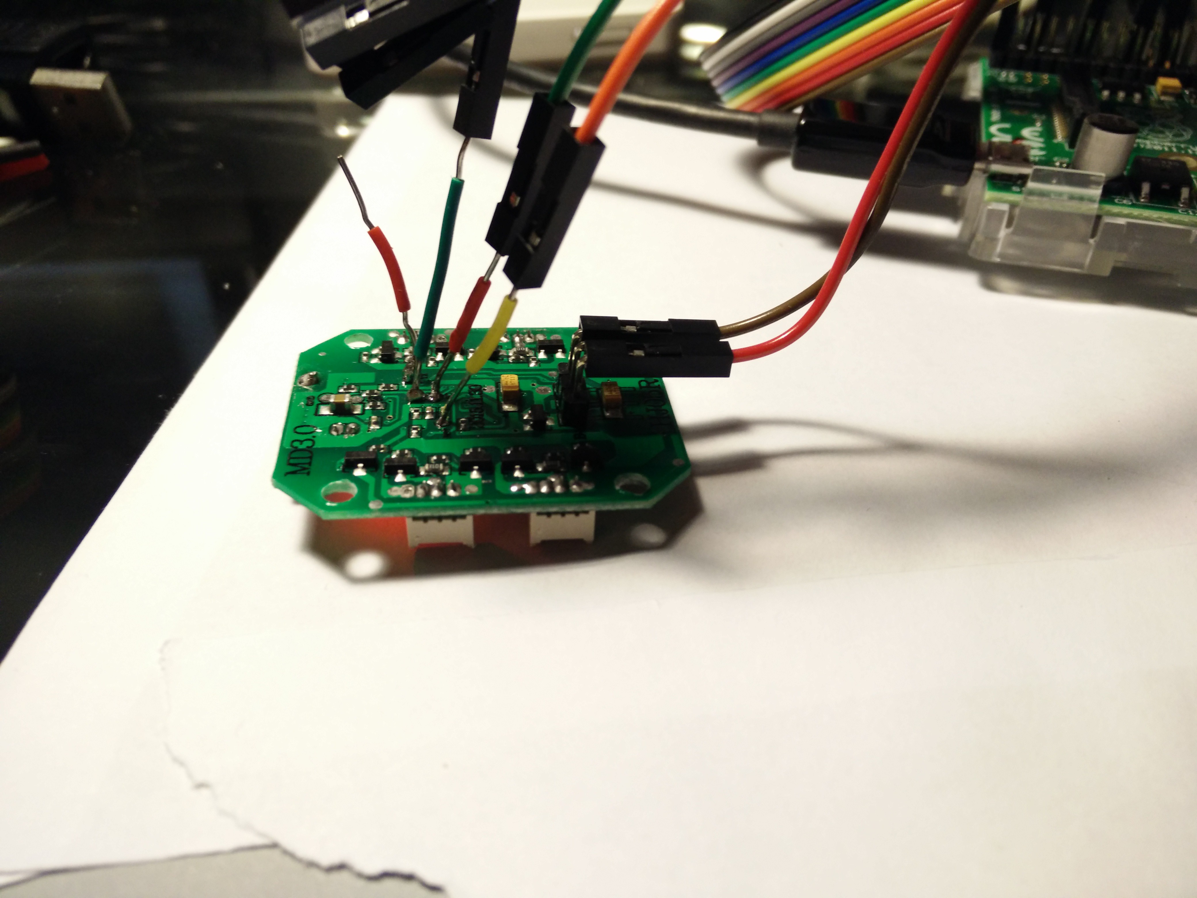
The communication
This was somewhere around 11:30pm (started around 7pm), so I was getting a bit tired, so the goal for the day was to be able to upload my own firmware, and blink the LED (connected on the PA1 port of the STM32).
With OpenOCD, I managed to get the basic communication up and running without a sweat, where when I launched it, it put the device into a "halt" mode, it also started a gdb server, to which I could attach my ARM gdb to, so debugging the code was also possible.
As a "strech goal" before starting to mess with the firmware, I wanted to take a dump of the existing firmware, to be able to restore it. Unfortunately I found out that the flash was read protected, so it was not possible to read it out. So that's that...
At this point, I had to decide between two options:
- Leave the existing firmware on it, and try to analyze the signals between the ICs to learn more about how they communicate
- Erase the flash and test my own firmware
I chose the second ;-) If for some reason I would need to debug the signals, I still have my "production" PCB in the quad that I could use to trace those signals.
The code
Developing for the STM32 can happen in 2 ways:
- Using the official toolchain + IDE: MDK which is supposed to be on Windows
- Go the open source way: GCC + libopencm3 + vim on Linux
And as you might have guessed, I went with option 2 again ;-)
I've fetched the latest barebone "GCC ARM Embedded" toolchain, which seemed to work after installing the 32-bit compatibility packages on my Ubuntu, and also cloned the libopencm3 example project.
The holy grail of any board bring-up is the blinking LED, so that's also where I started.
I've compiled the example code, modified the LED GPIO to be the one on PA1 (which I traced by looking at the PCB layout), and modified the loader to setup the correct flash and ram size. Once that was done, a simple "make; make flash" has given me a "miniblink.hex" file, which I managed to upload to the microcontroller using OpenOCD.
And voila! The MD3.0 was running my code!
Next Up
- Figure out a way to print messages over SWD: Since we don't have UART, it would be very useful for debug with more than just a LED blink, especially when we get to reading out sensor, RX data :-)
- Trace the connections between the STM32 and the MPU+RX.
- Try to get deeper into alternate firmwares. There seems to be two to choose between that are the least effort: bandwii or multiwii. Will need to try to compile them, remap the PINs and see if anything else is missing. Once that works, then the real fun begins :-)
Stay tuned for more updates!
Discussions
Become a Hackaday.io Member
Create an account to leave a comment. Already have an account? Log In.
Amazing! Great work! Thanks 😉
Are you sure? yes | no
Cool!
hope you get this thing better :-)
Thank You!!
Are you sure? yes | no