 dudeskidaddy
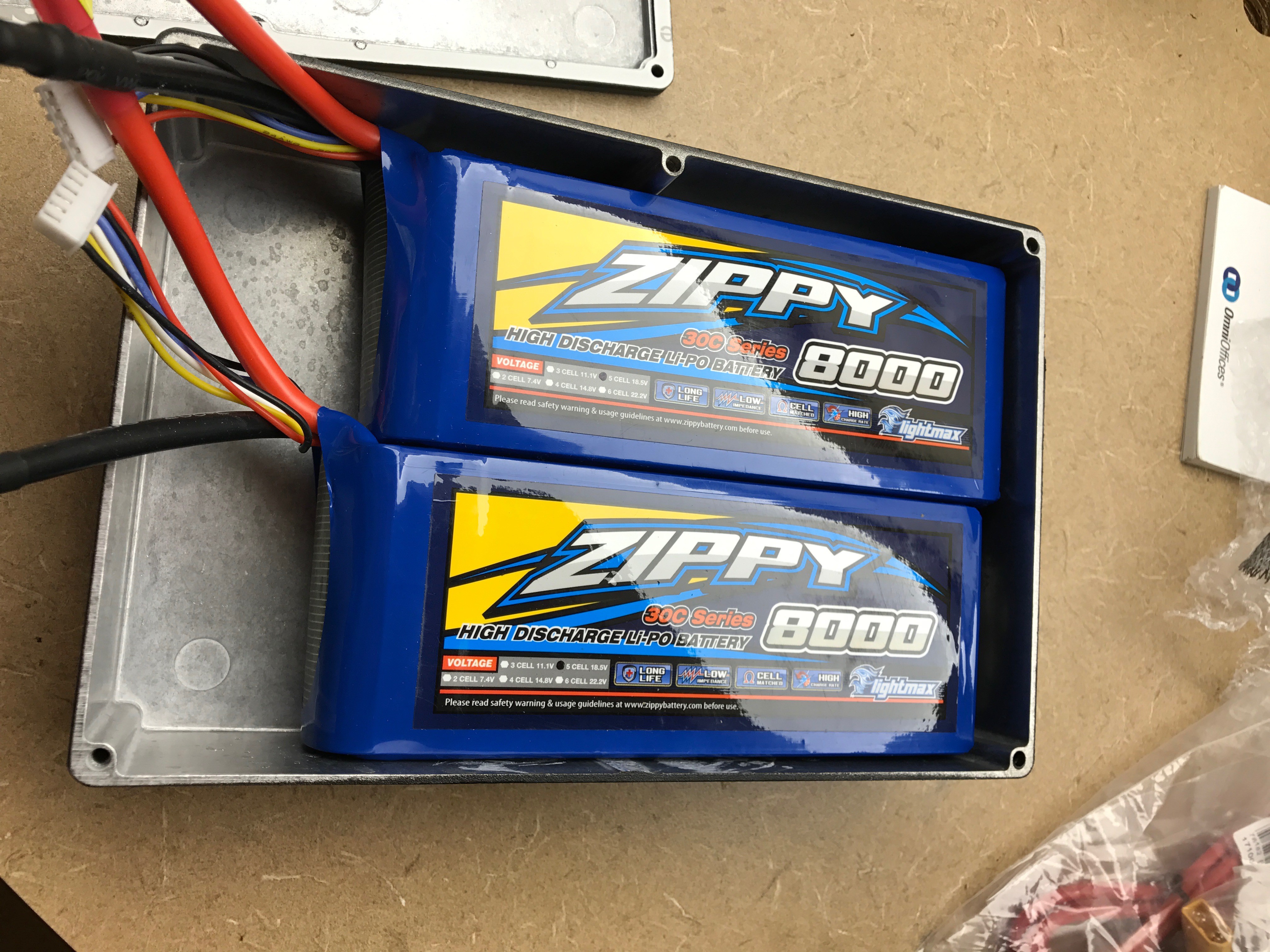
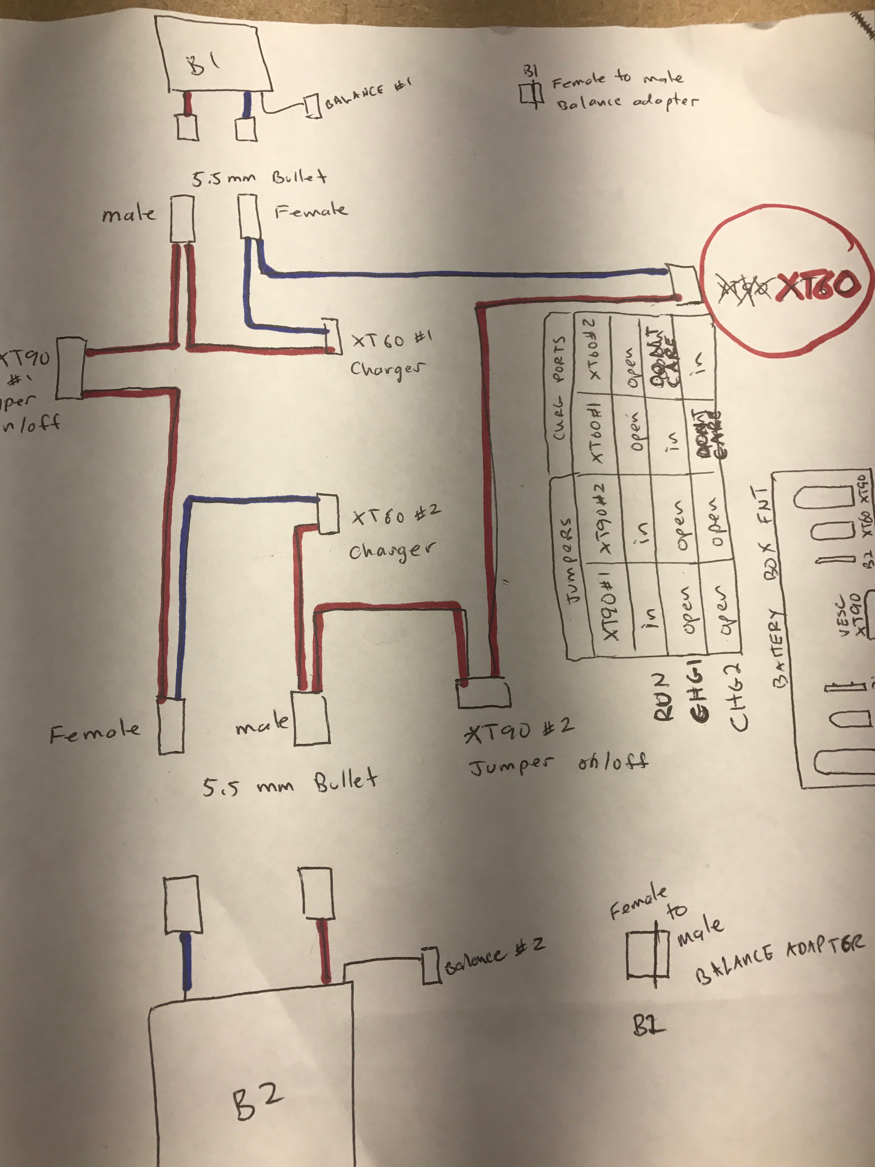
Wiring Schematic for the battery box 2x5s series = 10s
The idea is to be able independently balance charge 2 batteries that are connected in series to the VESC without having to open up the box. You can't just put a charger on the series output and performa balance charge. The batteries need to be isolated. Ideally, all the ports to both ARM and balance charge are accessible from the outside and done in such a way that prevents accidentally hooking up the wrong thing and causing a fire...or worse. All the wiring has to fit in the space and the ports will be mounted and glued through the box.
There will be 2 XT90 "Anti-Spark" Jumpers that both need to be plugged in to "arm" the board. When the jumpers are out the batteries are completely disconnected from each other and the positive terminal to the VESC. Both batteries could then be charged at the same time or independently via the XT60 ports. Again, all these XT ports and both battery's 5s balance ports will be permanently mounted through the battery box and we won't need to open the box or unplug any wires.
Why use both XT60 and XT90?
The jumper ports (XT90) are intentionally different types than the charger and output ports (XT60). This is to prevent accidentally shorting PWR/GND with the arming jumpers which would be bad.
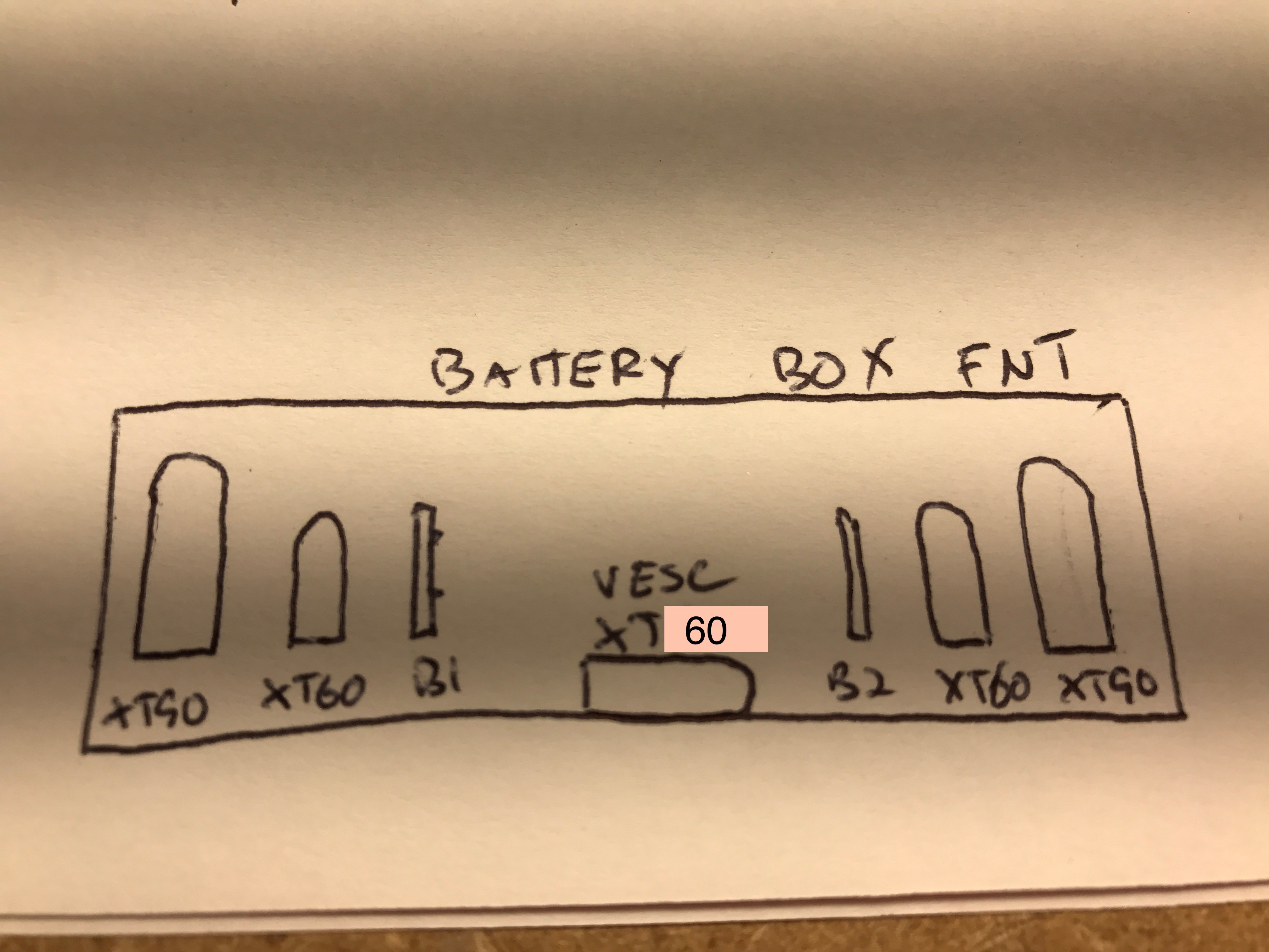 Terminal ports...on the back side of the battery box. This side faces backward on the board. The jumpers would be dangerous if you put one on a charge or output port. But since the jumpers are XT90, they can only be used to connect to the XT90 jumper port and won't fit the others.
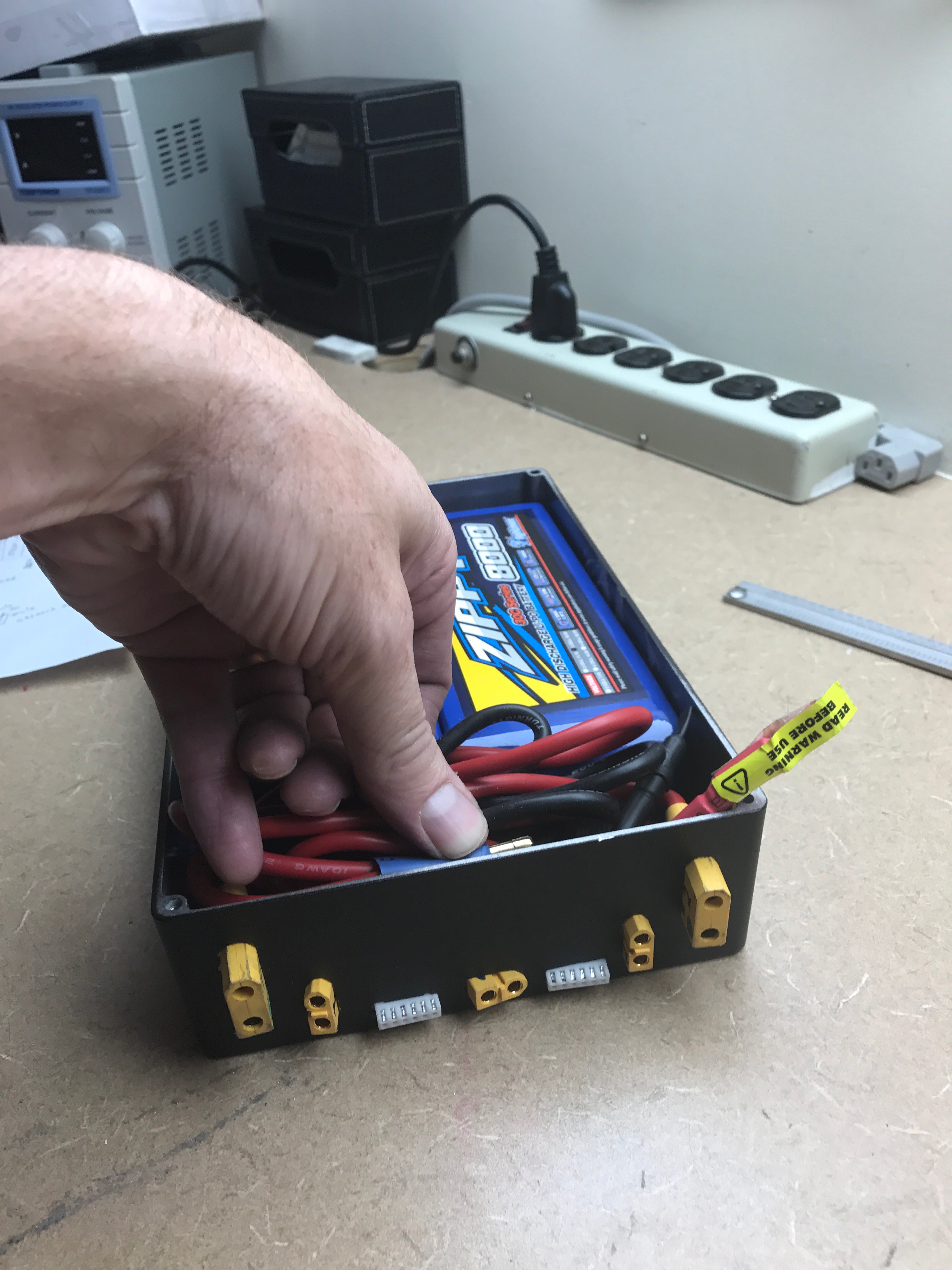
Here is the whole mess all soldered and hooked up to the LIPOs.
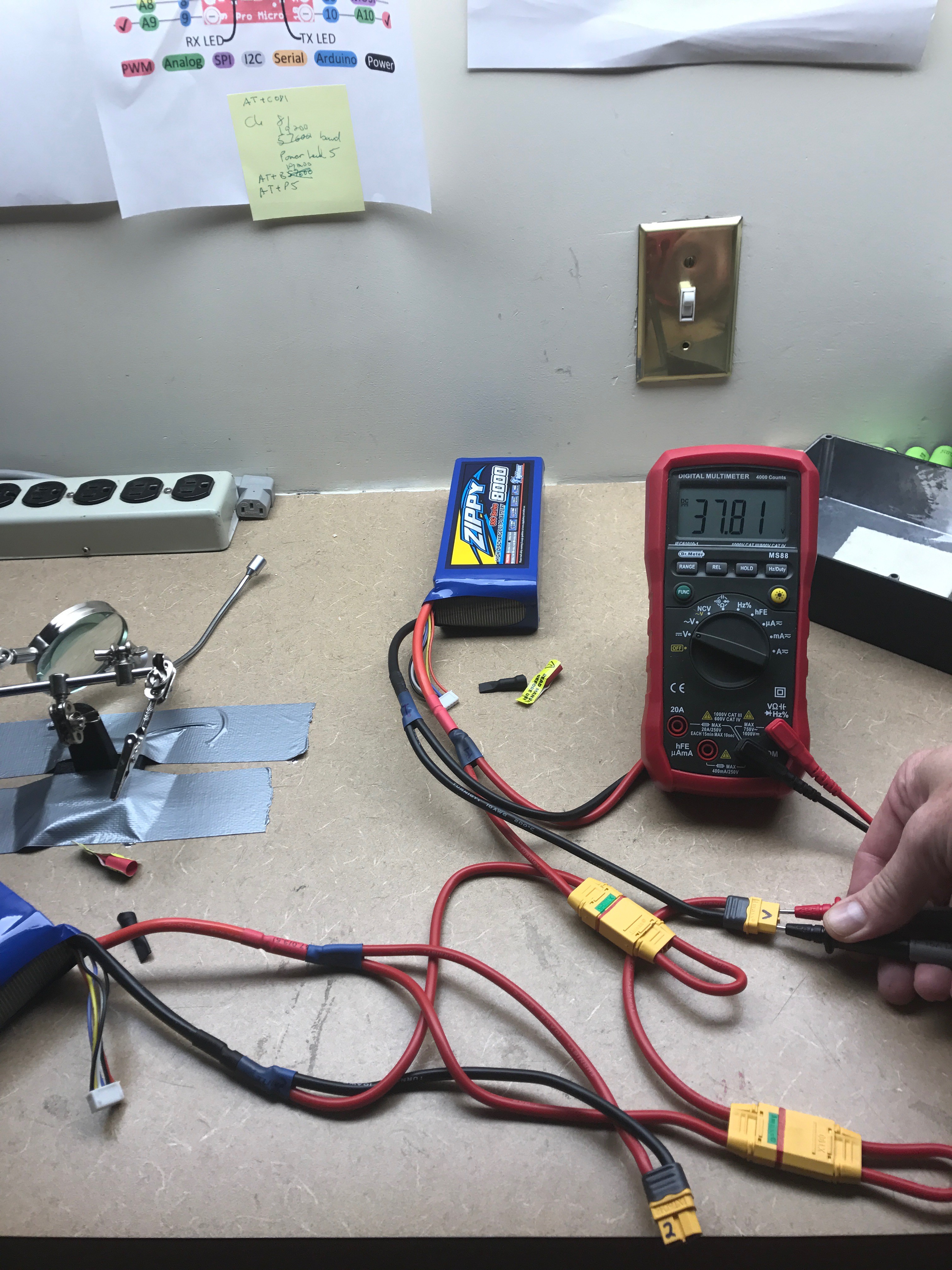 Both 10s batteries ( storage-charged at 50%) showing 37.81V. Note the 2 XT90 Jumpers in place. All this stuff has to fit in the small area in front of the batteries. I could have used shorted wires, but based on past experience I personally think it's easier to fit longer ones. Usually it's getting them to bend the way you need them to is the hardest part...not fitting all that wire..and longer wires are easier to bend. We'll see. I haven't mounted to the box yet and crammed it all in. I think it will fit.
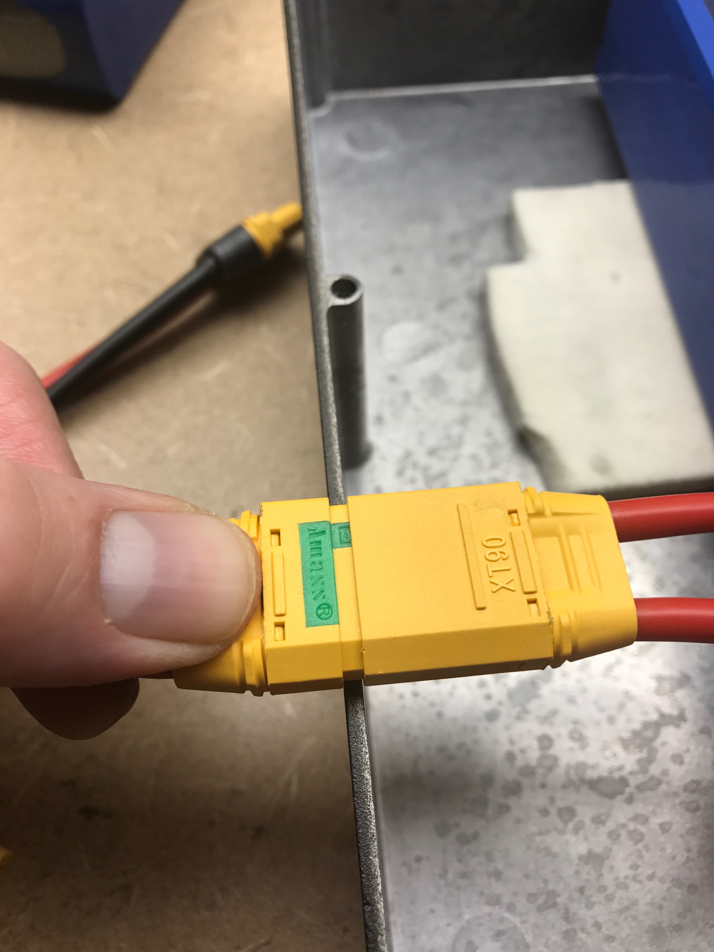
A problem with the XT90 anti-spark jumper:
Before connecting the batteries, I tested each port using the multimeter (Ohms) . I just wanted to make sure I soldered it according to the schematic and in particular didn't do something stupid that would short the batteries. This much energy in one place kind of freaks me out a little bit. Anyway, turns out the XT90 Anti-spark jumpers don't connect unless they are inserted ALL THE WAY! This is a problem since the box is about 2.5mm thick and will hold off the plug by that much. The jumpers are not conducting in this configuration...they have to be completely seated to work.
Thats the port on the left that will be mounted through the box and glued. The jumper is on the right. Like before, the mounting method takes advantage of the XT90's raised edge to provide extra resistance to pulling forces...glue isn't enough. Since these jumpers are going on and off every time the board is used...they have to be rock solid.
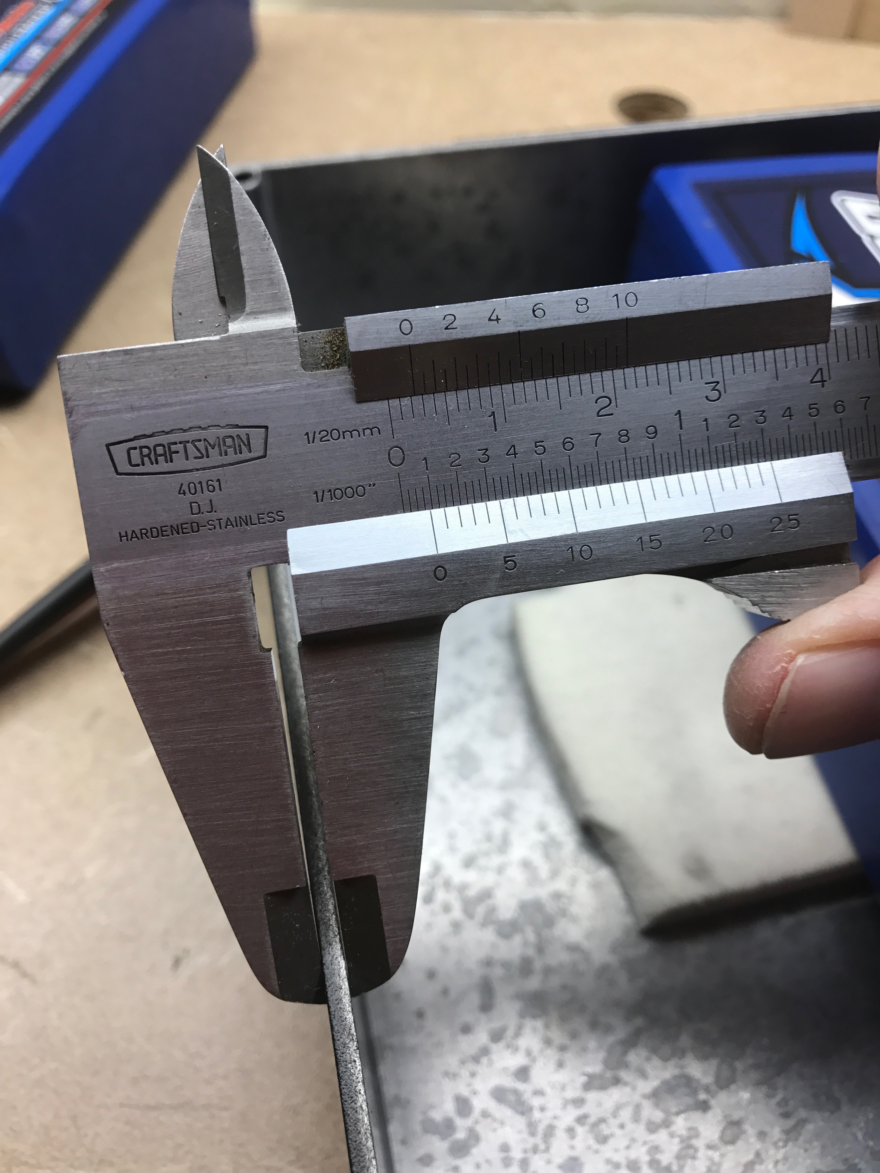
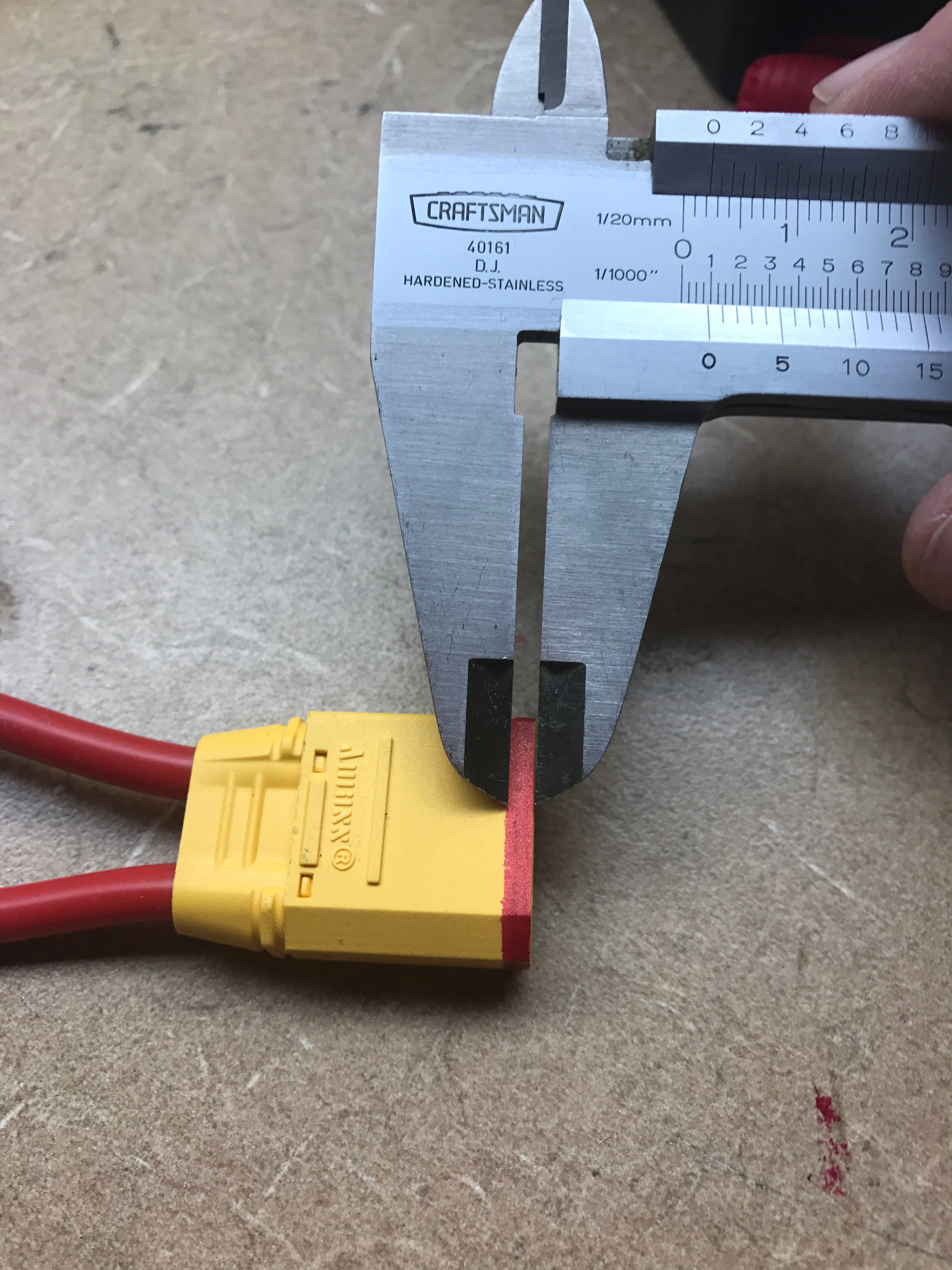
XT90 anti-spark....not sure if they're the best choice.
So apparently there is only about 2mm of contact distance on an XT90 Anti-spark plug...pretty bad. In these anti-spark units, there are 2 contact points, the first one near the outside has a little resistance to prevent the spark, and the second part of the contact near the back is fully connected. There is an insulator between. I bet the regular XT90s have more than 2x the contact area. Definitely the weak link in the power supply. Wonder if anyones written about this?
Hooked up and the wires fit...just barely.
Next step is sand, and epoxy everything in place, put labels on the various ports. I made the balance lead horizontal and moved to the bottom to make more room for the wires.
Discussions
Become a Hackaday.io Member
Create an account to leave a comment. Already have an account? Log In.